

How to Choose Press Brake Tools
Quickly select the right punches and dies based on material, thickness, V-opening, angle, and tonnage.
At CAMT, we specialize in press brake tooling and provide professional selection support and custom solutions for global sheet metal bending projects. Designed for procurement teams, engineers, and process specialists in sheet metal fabrication, enclosure manufacturing, HVAC, and automotive manufacturing.
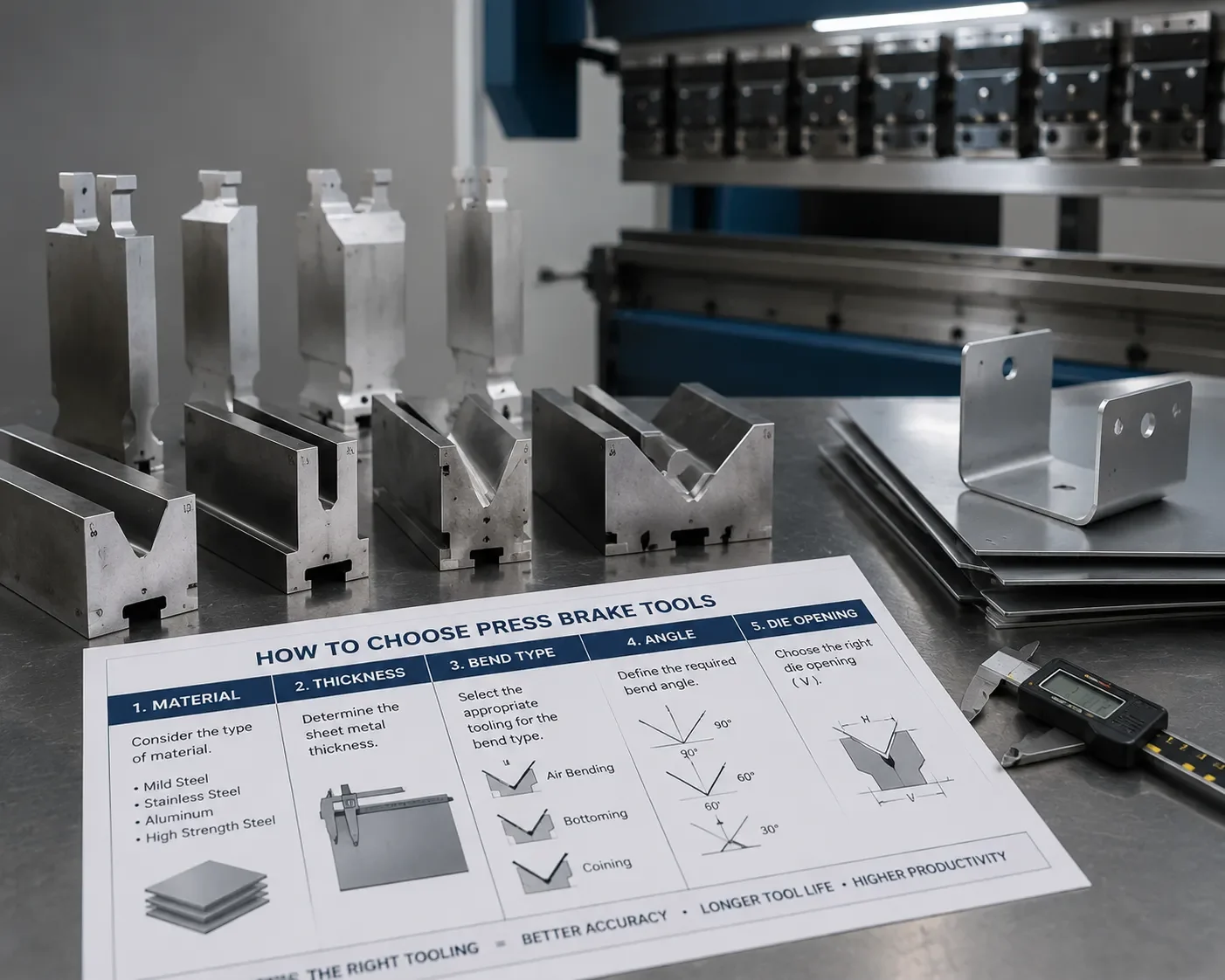
Precision CNC Punch & Die Selection Diagram for Sheet Metal Bending
4 Critical Inputs to Confirm Before Tooling Selection
Define these core parameters upfront to eliminate trial-and-error, protect your press brake equipment, and ensure accurate bend angles from the first stroke. Start with the right press brake tooling to match the job before production begins.
Material Type
01What to Confirm
- Carbon steel
- Stainless steel (304/316)
- Aluminum alloys
- Galvanized sheet metal
- High-tensile specialty alloys
Why It Matters
Material tensile strength governs tonnage requirements and springback. Stainless steel requires significantly more force and larger V-openings than mild steel or soft aluminum.
Common Mistake Alert
Using mild steel V-opening rules on high-tensile stainless steel, leading to extreme tonnage spikes, die galling, or permanent punch fracturing.
Sheet Thickness Range
02What to Confirm
- Minimum and maximum sheet gauge
- Raw material thickness tolerance
- Multi-gauge job rotation frequency
Why It Matters
Proper V-die sizing directly scales with sheet thickness. Batch gauge fluctuations shift the neutral bend axis, causing angle inconsistencies across production runs.
Common Mistake Alert
Sizing tooling strictly for nominal thickness without accounting for sheet mill variations, resulting in unexpected 1° to 2° angle drifts.
Bend Angle & Tolerances
03What to Confirm
- Standard 90° right angles
- Acute angles (e.g., 30°, 45°, 60°)
- Obtuse or shallow bends
- Springback compensation allowance
Why It Matters
To achieve a true finished angle during air bending, punch profiles must compensate for material elastic recovery by overbending to an acute angle prior to release. The right press brake punches help control that recovery more consistently.
Common Mistake Alert
Selecting a 90° punch to form a finished 90° stainless bend—without overbending allowance, springback will leave the part underbent.
Forming Geometry & Profile
04What to Confirm
- Standard air bending
- Large radius bending
- Hemming and edge flattening
- Offset (Z-bend) profiles
Why It Matters
Flange return clearances and complex cross-sections require specialized punch shapes such as gooseneck punches to avoid workpiece interference.
Common Mistake Alert
Using straight punches for deep channel or box profile bends, resulting in collision with the punch body on the second bend sequence.
Press Brake Equipment Specifications
Cross-check machine limits against tool physical dimensions and pressure capacities.
Max Tonnage
Ensure maximum bending load per foot/meter stays within tool and bed safety limits.
Working Length
Defines maximum tool length, sectioning layout, and side-loading capabilities.
Tooling Interface
Verify system compatibility (e.g., Amada/Promecam, European Precision, American, Trumpf-Wila).
Clamping System
Manual, hydraulic, or pneumatic clamping dictates tang style and setup speed.
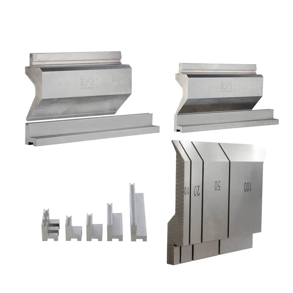
Turn Part Parameters Into Precise Tooling Configurations
Evaluating your material grade, thickness variations, angle precision, and profile constraints prevents costly trial runs and tool overloading.
At CAMT, our engineering specialists analyze your specific fabrication requirements to match your machine specs with optimized punch and die combinations.
- Prevent tool overloading and premature wear through engineered tonnage calculations
- Eliminate part collision risks on complex bends with pre-production CAD review
- Ensure seamless setup compatibility across standard and quick-change clamping systems
Selecting Punches and Dies by Material and Sheet Thickness
Matching Tooling Parameters to Material Specs
Selecting press brake tooling by material grade and thickness dictates precise bend accuracy and tool longevity. Material tensile strength, springback behavior, and bend radii directly drive required V-opening sizes and punch tip profiles.
Essential Tooling Rules
- • V-Opening Scale: Thicker materials require wider V-groove openings to handle force and maintain minimum bend radii.
- • Process Compensation: Harder materials exhibit severe springback, requiring acute punches and precise radius matching.
Material-Specific Guidelines
Carbon Steel Precision
Standard V-dies and standard tip punches deliver an optimal balance between high production efficiency and tooling cost.
Stainless Steel Rigidity
Requires press brake tooling for stainless steel designed for higher compressive strength, springback control, and wider V-grooves.
Aluminum Surface Care
Focuses on surface protection, larger punch radii, and low-marking die geometries to avoid surface galling.
V-Die & Punch Selection Matrix
Recommended tooling setup based on material thickness, type, and bending requirements
V-Opening: 8× Material Thickness (8V)
Punch Radius: Standard Tip Radius
Focus: Balanced efficiency, standard cost profile.
V-Opening: 10×–12× Material Thickness
Punch Radius: Larger Radius / Hardened Tip
Focus: Springback control, extreme compressive strength.
V-Opening: 6×–8× Material Thickness
Punch Radius: Smooth / Larger Radius
Focus: Lower marking risk, cracking prevention.
V-Opening: 6× Material Thickness
Punch Radius: Small Precision Radius
Focus: Low tonnage, deformation protection.
V-Opening: 10×–12× Material Thickness
Punch Radius: Heavy-Duty Large Radius
Focus: High tonnage matching, wear resistance.
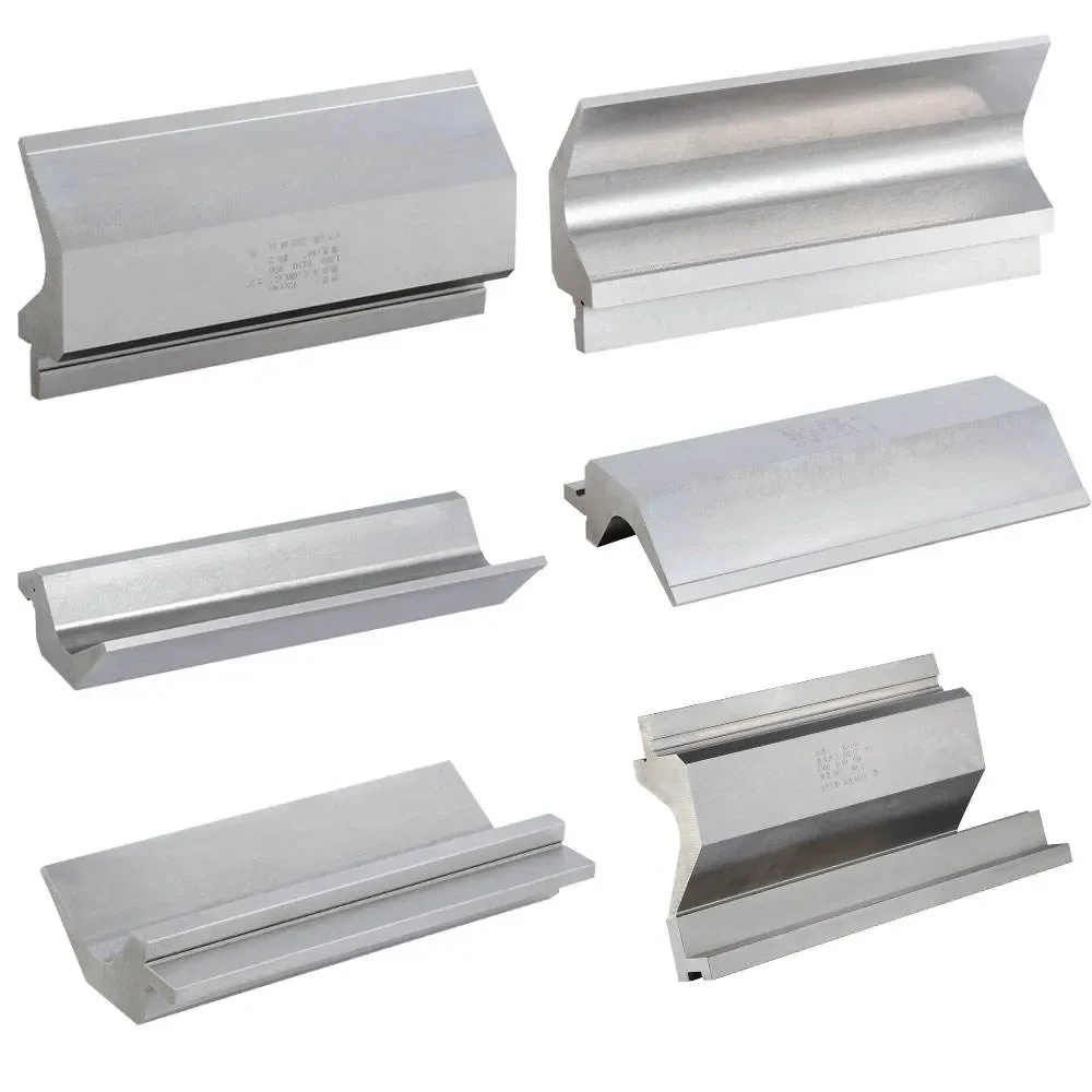
Matching Punch and Die Profiles to Bending Requirements
Selecting the correct press brake punch and die geometry ensures precise bend angles, prevents material interference, and protects your equipment. CAMT provides press brake tooling, including standard punches, gooseneck profiles, radius tooling, and custom die sets engineered specifically to match your part drawings and production needs.
Standard Punches
The foundational punch geometry for general fabrication, designed for primary straight-line air bending and standard bottoming.
Universal 90-degree sheet metal bends, simple channels, and flat profile forming.
- High structural strength and maximum tonnage rating
- Cost-effective general-purpose punch for everyday operations
Gooseneck Punches
Designed with an inverted throat recess that provides deep relief for pre-formed return flanges during secondary bend sequences.
Bending deep U-channels, electrical enclosures, and parts with narrow return flanges.
- Prevents workpiece collision during complex bend sequences
- Allows production of deep, narrow profiles without re-tooling
Radius Punches
Engineered with prominent tip radii to form uniform rounded contours without cracking high-tensile material or scoring surfaces.
Large-radius forming, structural plate, and high-finish cosmetic panels.
- Eliminates stress cracking on aluminum and high-tensile steel
- Delivers smooth, mark-free outer radius dimensions
Offset Punches
Specialized punch and die sets engineered to produce Z-bends and double offsets in a single stroke to maximize productivity.
Overcoming tight profile clearance constraints and forming high-volume Z-offsets.
- Executes two bends simultaneously in one press brake stroke
- Maintains strict pitch tolerances between adjacent bends
V Dies
Essential lower die blocks available in single-V, double-V, or multi-V openings to control bending force and angle accuracy.
Regulating required tonnage, bend radius, and minimum flange length across sheet thicknesses.
- Proper V-opening selection minimizes machine tonnage demands
- Ensures precise springback control for consistent angles
Hemming Tools
Two-stage tooling systems that pre-bend sheet metal to an acute angle and then flatten it completely in a second operation.
Creating safe handling edges, reinforcing cabinet panels, and sealing sheet margins.
- Eliminates sharp burrs and dangerous exposed sheet edges
- Doubles edge rigidity without requiring additional components
Need Custom Tooling Advice Based on Your Drawings?
Not sure which punch profile fits your bend sequence? CAMT engineers can review your part files to recommend the ideal combination of standard, gooseneck, or custom punch and die configurations for optimal accuracy and tool life.
How to Calculate V Opening, Tip Radius, and Bend Angles
Master the technical relationships between V-die width, punch tip radius, and angle control to achieve precise, repeatable bending results with the right press brake tooling on every press brake setup.
V-Opening Width & Material Thickness (8× Rule) ↓
The baseline calculation uses the industry standard V = 6–10 × t (where t is sheet thickness). Selecting the correct opening ensures accurate tonnage distribution and minimal material cracking.
- Mild Steel (t ≤ 3 mm): V = 6–8× t
- Stainless Steel / Hard Alloys: V = 8–10× t (prevents excessive tonnage and tool wear)
- Aluminum Sheet: V = 6–8× t (reduces surface galling)
Punch Tip Radius: Imprint Marks, Springback & Radius Control ↓
Punch tip radius determines the inner bend radius ($R_i$) for the press brake punches you choose. A sharp punch concentrates pressure to lower springback, while a larger radius protects sensitive cosmetic surfaces.
- Tip Radius < 0.63× t: Risk of creasing material and creating sharp stress points
- Tip Radius = 0.63–1.0× t: Optimal for air bending standard sheet metal
- Tip Radius > 1.0× t: Ideal for non-marking aluminum/stainless, requires higher springback allowance
Matching Tooling Geometry to Bending Profiles ↓
Selecting punch profiles according to required bend angles prevents tool interference and part distortion:
- Acute Bends (<90°): Requires 30° or 45° sharp punches and narrow V-dies for overbending
- Right Angles (90°): Standard 88° or 90° punch profiles for air bending or bottoming
- Obtuse Bends (>90°): Wide V-dies with large radius punches to maintain smooth geometry
Springback Compensation & Precision Angle Control ↓
Every metal springbacks upon pressure release. To achieve exact final angles, punch angles must be overbent past the target line:
- Carbon Steel: Allow 1°–2° of springback compensation
- Stainless Steel: Allow 2°–4° of springback compensation
- Aluminum Alloys (5052/6061): Allow 3°–5° of springback compensation
- High-Yield Alloys: Require acute tooling (30°–45°) for up to 8° overbending
When to Switch from Standard to Custom Press Brake Tooling ↓
While standard punches and dies satisfy 80% of jobs, custom engineered tooling is necessary when:
- Drawing specifications mandate bend tolerances tighter than ±0.5°
- Special flange offsets, channel returns, or double-bends cause clearance collisions
- Heavy plate thickness requires non-standard V-openings with hardened inserts
Essential Bending Calculation Formulas
Recommended V-Die Opening (V)
V = 6 to 10 × t
Minimum Inside Bend Radius ($R_i$)
R_i = 0.156 × V
Punch Angle with Springback Compensation
θ_punch = θ_target - Δθ_springback
Bend Allowance Formula (BA)
BA = (π/180) × (R_i + K × t) × θ
K-factor: 0.33 (air bending) to 0.45 (bottoming)
Tooling Parameter Interaction
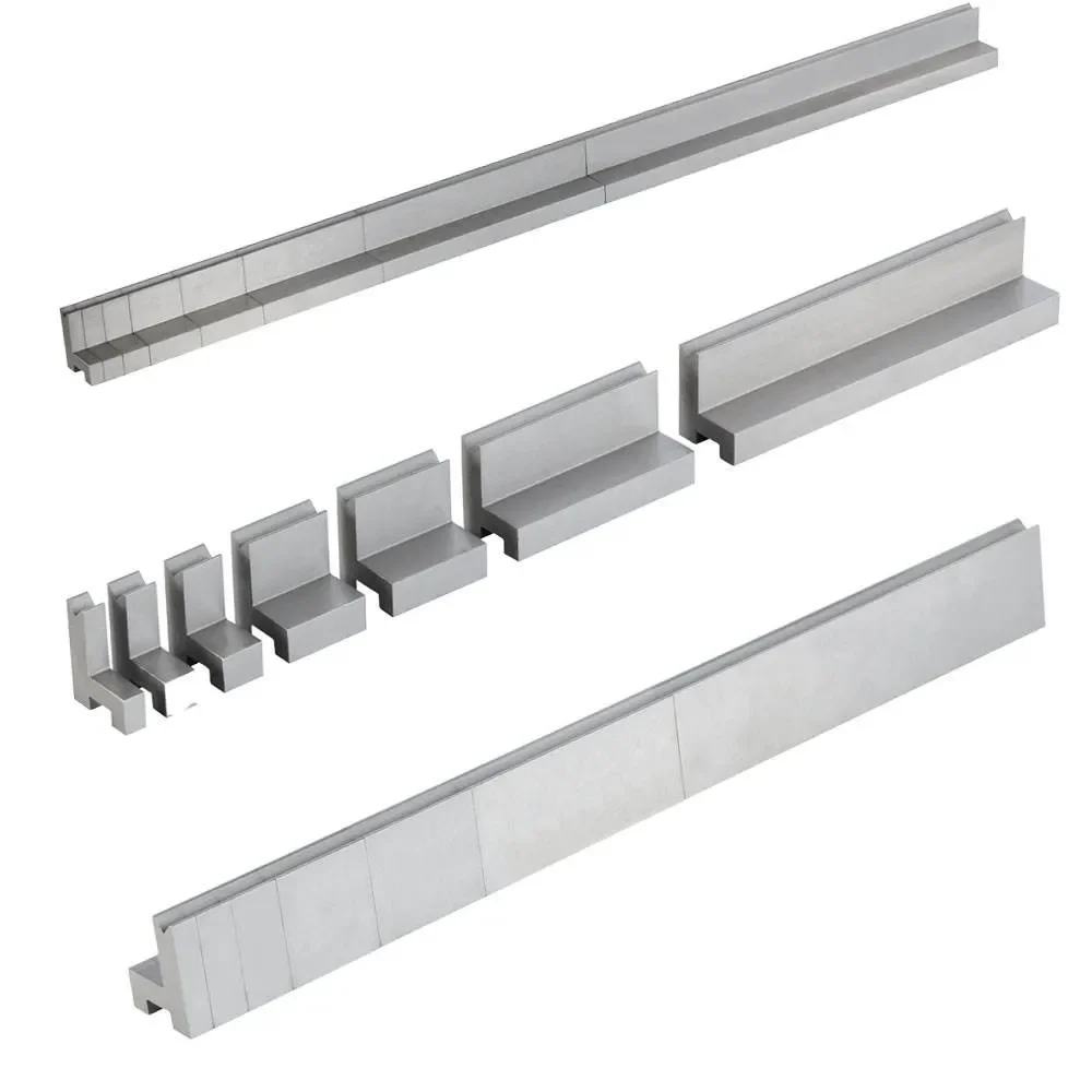
Interlocking variables: V-die opening width, punch tip radius, and material springback dictate final part accuracy.
V-Opening Selection Risks: Oversized vs. Undersized Dies
Compare parameters to ensure optimal tool life, force distribution, and dimensional tolerance.
| Evaluation Criteria | V-Opening Too Small (< 6× t) | V-Opening Too Large (> 12× t) | Optimal Range (6–10× t) |
|---|---|---|---|
| Tonnage Requirement | Excessive force needed — risks overloading press brake | Low tonnage required, but poor angle control | Balanced force distribution & rated tool safety |
| Surface Finish Quality | Severe die contact lines and surface indentations | Minimal tool marks, but higher risk of sheet distortion | Clean surface finish with minimal contact scarring |
| Angle Consistency | High stress concentration causes angle variance | Large, unpredictable springback error across batch | Stable angle repeatability within tight tolerances |
| Tool Wear & Lifespan | Accelerated wear and chipping on die shoulders | Uneven shoulder pressure on large radii | Uniform wear across precision-ground die shoulders |
| Material Cracking Risk | High risk of fracture on high-tensile steels | Low cracking risk, but inner radius exceeds print specs | Eliminates bend-line cracking on standard alloys |
Need Help Selecting the Right Tooling Configuration?
Share your part drawings, material specifications, and press brake parameters. CAMT engineers will evaluate bend requirements, tonnage limits, punch geometry, and V-die selection to recommend the optimal tooling solution.
Technical feedback within 24 hours
Common Tooling Selection Mistakes and How to Avoid Them
Avoid costly press brake tooling errors. Our engineering team helps fabricators identify critical selection mistakes early to eliminate failed trial runs, protect machinery, and reduce rework costs.
Mistake 1 — Buying strictly on initial tool cost
Selecting punches and dies based only on price without evaluating material tensile strength or required tonnage limits.
Correct Approach
Calculate exact tonnage requirements and match tool load limits to your specific sheet metal grade before purchasing.
Mistake 2 — Sizing the V-opening too small
Using an undersized lower V-die, which causes sharp tonnage spikes and accelerates premature tool wear or breakage.
Correct Approach
Apply the standard 6–10× material thickness rule to keep press brake bending forces within safe operational thresholds.
Mistake 3 — Ignoring material springback
Failing to account for elasticity variations across steel, stainless, or aluminum, leading to out-of-spec bend angles.
Correct Approach
Select punches with appropriate tip radii and angle compensation to account for material-specific recovery values.
Mistake 4 — Overlooking part clearance
Using standard straight punches on complex profiles, resulting in collisions with existing return flanges during forming.
Correct Approach
Review part geometry early and specify gooseneck punches or offset punches to provide the required relief space.
Mistake 5 — Unstandardized batch parameters
Operating without standardizing tooling setups across different raw material batches, causing inconsistent angle drift.
Correct Approach
Establish and log validated CNC controller settings per material thickness and supplier batch to ensure uniform bend quality.
Get Expert Tooling Guidance from CAMT
Our engineering support team evaluates your part drawings, tonnage limits, and material specs to prevent tooling mismatches before you order—saving time, protecting equipment, and lowering scrap rates. We also help you choose the right press brake punches for demanding applications.
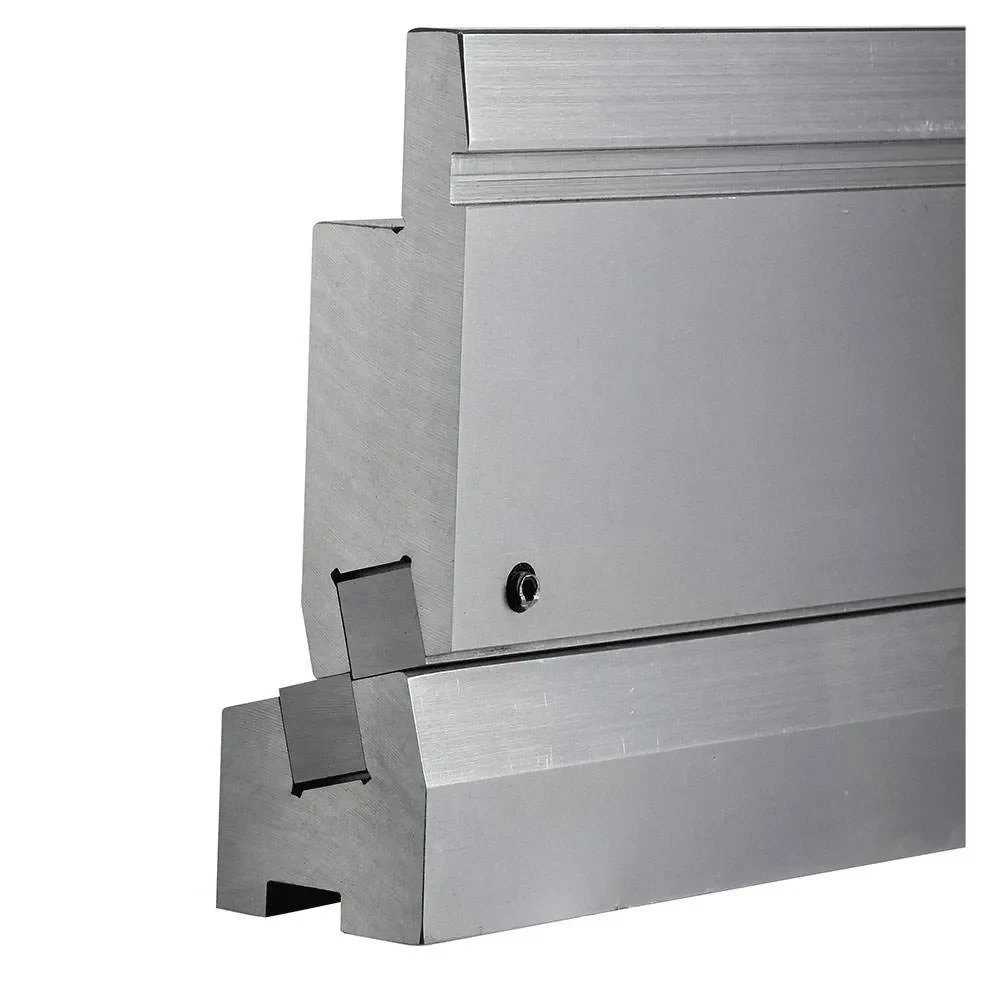
Recommended Selection Process: From Drawing to Order
Streamline your tooling procurement. Follow our structured 5-step engineering review to ensure optimal die selection, precise springback compensation, and seamless production startup for press brake tooling projects.
Gather Key Data
Consolidate part CAD drawings, material tensile strength, sheet thickness, and machine clamping dimensions.
Submit 2D/3D prints and machine interface specs.
Define Criteria
Identify target bend angles, cosmetic surface limits, special radii, and batch production volumes.
Highlight critical flanges and mark appearance faces.
Preselect Tooling
Match profile geometries to standard press brake punches, gooseneck punches, or specialized radius and V-die configurations.
Review standard punch and V-opening options.
Verify Engineering
Calculate required press tonnage limits, check for part interference, and account for springback allowances.
Perform tonnage safety & clearance verification.
Finalize Order
Confirm tooling segmentation, hardening treatments, lead times, and initial sample validation requirements.
Approve technical quotation and production plan.
Tailored Recommendations for Every Bending Challenge
Our engineering team assesses your part geometry to deliver the ideal balance between tool longevity, setup speed, and cost efficiency.
Standard Tooling
In-stock punches and dies for fast delivery on common profiles.
Custom Engineering
Specialized offset punches and die profiles designed for complex parts.
Design Optimization
DFM recommendations to minimize stroke stages and tooling costs.
Automated collision checking and tonnage validation by CAMT technical specialists.
Accelerate Your Custom Tooling Project
Partner with CAMT for reliable OEM and ODM press brake tooling solutions. Upload your drawings today for rapid manufacturability analysis, precise tool selection support, and a fast, transparent quotation.
Ready to review your drawings?
Why Choose a Professional Custom Press Brake Tooling Partner
At CAMT, we supply global fabricators with high-hardness tool steel, precision grinding, and custom press brake tooling engineered to ensure long-term bending accuracy and stable production.
Precision Grinding
Advanced CNC grinding maintains tight tolerance control across working surfaces, improving tool alignment and ensuring consistent bending accuracy across long production runs.
Heat Treatment
Deep hardening and targeted surface heat treatment processes maximize core strength and wear resistance, allowing tools to withstand high tonnage without premature chipping.
CNC Machining
Multi-axis CNC manufacturing enables repeatable execution of complex geometries, gooseneck profiles, and custom V-die dimensions matched to your exact drawings.
Fast Delivery
Efficient production scheduling and stocked standard tool blanks help shorten lead times, helping you avoid press downtime and meet tight project schedules.
Global Export Experience
Proven international shipping processes and standard-compliant clamping system support ensure seamless integration with European, American, and Japanese press brakes.
Technical Support
Our application engineers evaluate part drawings, verify tonnage requirements, and perform collision checks to confirm tooling suitability before production starts.
Full-Spectrum OEM & ODM Customization
Whether you need standard punch and die replacements or specialized press brake punches and OEM/ODM press brake tooling for complex bending profiles, CAMT offers complete manufacturing oversight—from raw material selection and heat treatment to final precision grinding.
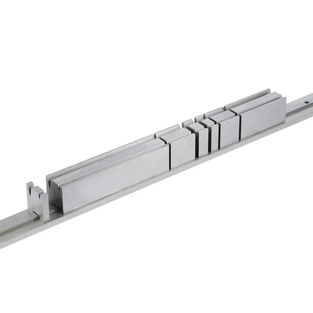
Frequently Asked Questions
Find rapid answers to press brake tooling selection, custom die fabrication, V-die sizing, and bending angle optimization.
How do I choose the correct V-opening size based on sheet thickness?
What is the main difference between stainless steel tooling and carbon steel tooling?
When should I choose a gooseneck punch?
How can I prevent unstable bend angles?
Can you manufacture custom punches and dies from our drawings?
What information do I need before requesting a quote?
Need Engineering Support?
Our CAMT technical support team helps customers quickly decide whether standard tooling or custom tooling is the best fit for a specific workpiece.
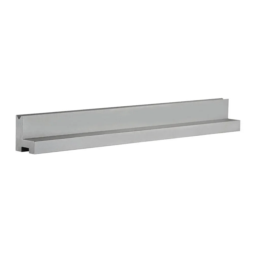
Optimize Your Press Brake Tooling Selection
Share your bending requirements, material specifications, and machine details. CAMT engineers will evaluate tooling compatibility, punch and die configuration, and recommend the most suitable solution for your production needs.
24-Hour Response
Fast engineering feedback
Drawing Review
CAD & specification check
OEM Support
Custom tooling solutions
Suitable for sheet metal fabrication, automotive components, HVAC systems, enclosures, and other precision bending applications worldwide.
Request Tooling Evaluation
Submit your drawings or production parameters. Our engineers will review your requirements and provide tooling recommendations.