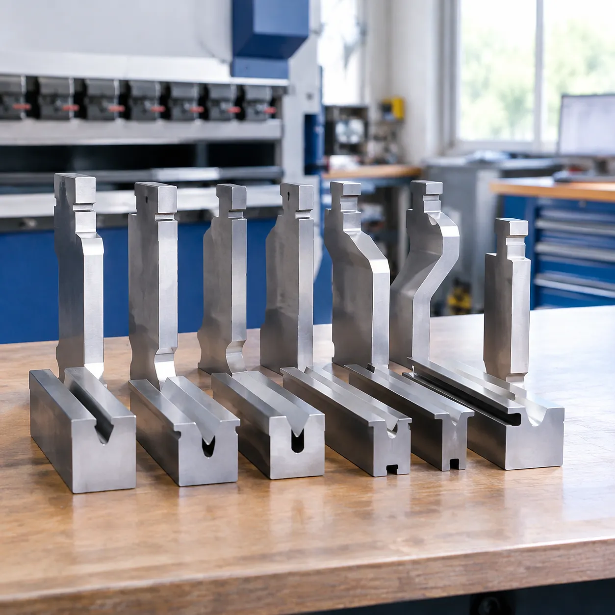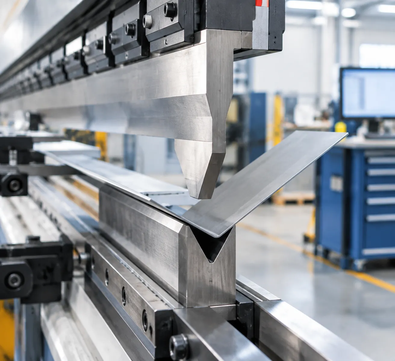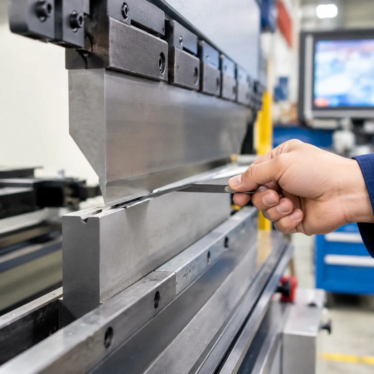
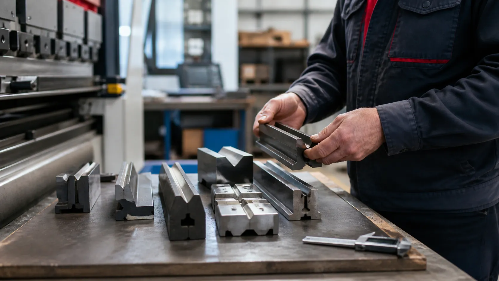
Struggling to figure out what press brake die should I use for your next metal fabrication project? Pick the wrong V-opening, and you risk ruined parts, unpredictable springback, or even damaging your machine with excessive tonnage.
In this guide, you'll master press brake die selection step-by-step—from applying the essential Rule of 8 to calculating exact bend radii and safe tonnage limits for perfect bends every single time.
Let's dive right in!
Press Brake Die Selection: Determining the Right V-Die Opening
The Standard 8 x T Rule for Mild Steel Bending
For standard air bending of mild steel between 0.8 mm and 6 mm thick, we rely on the industry benchmark:
- Formula: V = 8 x T (Where V is the V-die opening width and T is the sheet thickness)
| Sheet Thickness (T) | Selection Formula | Target V-Die Opening (V) |
|---|---|---|
| 1.0 mm | 8 x 1.0 mm | 8 mm |
| 1.5 mm | 8 x 1.5 mm | 12 mm |
| 2.0 mm | 8 x 2.0 mm | 16 mm |
| 3.0 mm | 8 x 3.0 mm | 24 mm |
| 6.0 mm | 8 x 6.0 mm | 48 mm |
When to Deviate from the 8 x T Rule
- Use 6 x T (Tight Radius / Thin Gauge): Choose a narrower V-die when a print demands a smaller inside radius or short flanges on thin material. Note: Expect required bending tonnage to increase by roughly 30% to 35%.
- Use 10 x T to 12 x T (Heavy Plate & Stainless): Essential for heavy plate (> 6 mm) and high-yield alloys like stainless steel. Opening the V-groove lowers press brake tonnage demand and reduces stress on both the material and tooling.
Inside Bend Radius Calculation and Preventing Micro-Fractures
In air bending, the punch nose tip does not force the final radius—the V-opening geometry controls it. The sheet forms a natural floated inside bend radius (Ri) during the stroke:
- Floated Inside Radius Formula: Ri ≈ 0.15 to 0.20 x V
- Mild Steel Average: Ri ≈ 0.16 x V
- Stainless Steel Average: Ri ≈ 0.20 x V
Floor Tip: If your calculated inside radius drops significantly below the sheet thickness (Ri < T), you risk forcing a sharp crease. This severe material tension causes micro-fracturing along the outer bend line, especially when bending parallel to the material grain direction. Opening your V-die widens the radius and eliminates cracking.
Press Brake Tonnage Calculation and Safety Limits
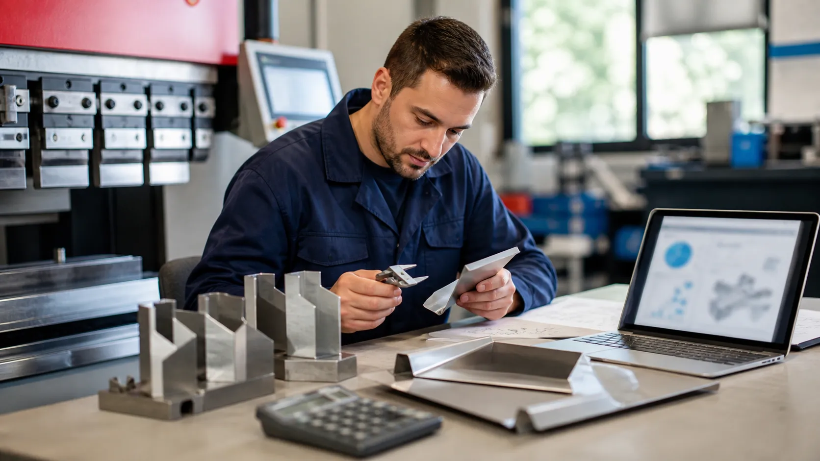
Calculating required tonnage is essential during press brake die selection to protect tooling and equipment from catastrophic overload. To find the required bending force for standard mild steel, we use the standard air bending formula:
P = (650 x S² x L) / V
- P = Required tonnage (kN)
- S = Sheet metal thickness (mm)
- L = Bending length (meters)
- V = V-die opening width (mm)
Different materials require specific multiplier adjustments to account for varying ultimate tensile strength (UTS):
Mild Steel: 1.0x (Baseline standard)
Stainless Steel: 1.5x (Requires 50% more force due to high yield strength)
Aluminum (Soft/Medium): 0.5x (Requires 50% less force than mild steel)
Always cross-reference your calculated values against a reliable press brake V-die chart and tonnage guide before cycling the ram under heavy loads.
Preventing Die Rupture with Enforced Load Margins
Exceeding the maximum load capacity printed on lower dies causes micro-fractures, structural deformation, or explosive die rupture.
To maintain complete shop floor safety, we enforce these strict tonnage parameters:
Safety Margin: Never exceed 80% of the maximum rated tonnage per meter (t/m) for any single V-groove.
Concentrated Loading: Short parts focus total ram tonnage over narrow surface areas. Always recalculate load density for short workpieces to prevent localized overload.
Air Bending vs. Bottoming: If bottoming instead of air bending, multiply the calculated tonnage by 4x to 5x and verify that your tooling rated limit supports the spike.
Minimum Flange Length Formula: Preventing Sheet Drop
Selecting a V-die that is too wide for short flange dimensions causes the sheet metal to drop straight into the V-groove before reaching the target angle.
To calculate the absolute minimum flange length required to bridge the die shoulders safely, apply the minimum flange length formula:
b_min = 0.707 x V
Where b_min is the minimum legal flange length (mm) measured from the outside apex, and V is the lower die opening width (mm).
| V-Die Opening Width (V) | Calculated Minimum Flange (b_min) |
|---|---|
| 8 mm | 5.65 mm |
| 12 mm | 8.48 mm |
| 16 mm | 11.31 mm |
| 25 mm | 17.68 mm |
Keeping your minimum flange length above this calculated threshold guarantees crisp form lines and prevents hazardous material slipping during the press brake stroke.
Matching Die Profiles to Complex Part Geometries
Selecting the correct tooling geometry goes beyond simple sheet thickness calculations. Part profiles, return flanges, and surface finish requirements dictate which die structure you need on the shop floor.
Multi-V Die vs Single V Die
For high-mix job shops handling varied sheet metal gauges, swapping individual dies for every job causes unnecessary setup downtime. We recommend using versatile multi-V dies to quickly rotate between multiple V-opening widths in seconds. For high-volume production, dedicated single-V dies paired with hydraulic clamping deliver maximum rigidity and exact centerline alignment.
Acute Angle Punch and Die Solutions
High-tensile alloys and stainless steel exhibit severe elastic recovery. Standard 88° or 90° dies cannot achieve a true right angle during air bending due to this effect. We utilize 30° to 45° acute angle punches and dies to overbend the material, allowing the metal to spring back precisely to the targeted 90° angle without bottoming out.
Hemming and Flattening Combinations
Producing safe sheet edges or high-rigidity seam folds requires a two-step process:
Step 1: Pre-bend the sheet edge to a 30° acute angle.
Step 2: Flatten the fold completely using a spring-loaded or combination hemming die set.
Using integrated hemming tooling allows operators to perform both operations in a single press brake setup, cutting cycle times in half.
Gooseneck Punch Clearance
Standard straight punches frequently collide with existing flanges when forming deep boxes or return channels. We utilize gooseneck punches to provide deep relief clearance, allowing complex side flanges to nest inside the punch recess during the stroke.
Polyurethane Mark-Free Die Inserts
Forming architectural stainless steel, mirror-finish aluminum, or pre-painted sheet metal requires protection against die-line galling. We protect cosmetic surfaces using high-durability polyurethane die inserts or protective urethane films applied directly across standard precision press brake V-dies. This cushioned layer prevents metal-on-metal contact and delivers pristine, mark-free bends.
Tooling Metallurgy, Precision Tolerances, and Quality Benchmarks
Micron-Level Precision Ground Tolerances
CAMT always insist on precision ground tooling with height tolerances held tight at ±0.01 mm.
- Eliminates Shimming: Standard planed dies require time-consuming paper or shim stock placement to correct height variations across long bend lines. Micron-accurate grinding eliminates shimming entirely.
- Instant Stage Setups: Precision ground height guarantees that different die segments loaded side-by-side across the bed maintain identical centerlines and height alignment.
Heat Treatment Standards for Tool Steel
Heat treatment determines how well a die resists deformation and wear over millions of bend cycles. We outline the key metallurgical tradeoffs in our press brake tooling material guide:
- Localized High-Frequency Induction Hardening (HRC 55–60): Hardens the critical V-shoulder contact zones to a depth of 2–4 mm while preserving a shock-absorbing core. This delivers 3x extended tool life compared to unhardened steel.
- Deep-Hardened Steel: Hardened through the entire tool body (typically HRC 28–32 or higher). Excellent for heavy-duty structural plates where massive tonnage capacity is required throughout the tool base.
Investing in properly hardened working radii is critical for extending press brake V-die lifespan and keeping your bend angles consistent across high-volume production runs.
Surface Roughness Impact on Friction and Galling
The surface finish on lower die shoulders directly impacts cosmetic part quality and tool drag.
- Ultra-Low Roughness (Ra < 0.8 µm): Precision-polished V-groove entry radii allow the sheet metal to slide smoothly into the die during air bending.
- Prevents Sheet Galling: Smooth die shoulders stop soft materials like aluminum and stainless steel from transferring metal debris onto the die, preventing severe die-line scratching on finished parts.
- Reduces Sliding Resistance: Lower friction results in smoother tonnage application and less strain on both the workpiece and the press brake ram.
Machine Compatibility & Press Brake Adapter Systems
Standardizing European Style vs. American Precision Clamping
Standardizing your punch and die profiles across European Style (Promecam), American Precision, and New Standard clamping systems allows operators to share dies between machines seamlessly.
- European Style Tooling: Utilizes a standard 13 mm x 20 mm tang with a safety key or groove, optimized for fast manual or hydraulic side-loading.
- American Precision Tooling: Features a 0.500 in (12.7 mm) wide center tang, traditionally secured with manual clamp bars or mechanical wedge systems.
- New Standard / WILA Style: Employs self-seating, hydraulic, or pneumatic push-button clamping with high-precision seating surfaces for automated setup environments.
We engineer hardened adapter blocks and upper/lower intermediate clamps that bridge the gap between these systems. By converting standard American or European press brake beds to accept universal precision-ground tooling, your shop maintains strict center-line alignment without expensive bed retrofits.
| Tooling System | Tang Width / Profile | Primary Clamping Method | Alignment Precision |
|---|---|---|---|
| European Style | 13 mm x 20 mm with groove | Hydraulic / Manual side clamp | ± 0.01 mm (± 0.0004 in) |
| American Precision | 0.500 in (12.7 mm) straight tang | Manual clamp bar / Wedges | ± 0.02 mm (± 0.0008 in) |
| New Standard | Self-seating pin / Express rail | Hydraulic push-button / Automated | ± 0.005 mm (± 0.0002 in) |
Drop-In Machine Compatibility Across Major OEMs
Tooling interchangeability requires exact shut-height matching, load-bearing shoulder alignment, and V-die center-line synchronization. Our precision-ground tooling line provides drop-in compatibility across all major machine manufacturers, ensuring your bend angles remain consistent regardless of which machine is running the job.
- Amada & Cincinnati: Direct-fit dies featuring standard shoulder radii and drop-in tangs eliminate the need for custom shims when running high-volume job runs on Amada press brake tooling setups.
- Trumpf & Bystronic: Precision seating surfaces engineered for hydraulic push-pin locking systems deliver instant self-alignment on Trumpf compatible tooling beds.
- LVD & WILA: Heavy-duty lower V-die bases designed to match narrow and wide table slots ensure rigid support under high-tonnage air bending applications.
Using precision adapters and multi-tang lower die bases prevents localized beam deformation, extends tool life, and lets operators switch production runs between different machine brands in minutes.
Custom Tooling Engineering & 3D Bending Simulation
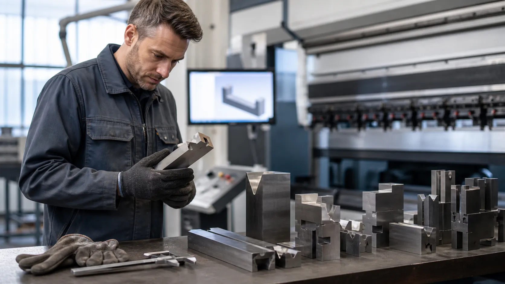
When Off-The-Shelf Dies Fail
Standard V-dies and punches handle the majority of daily shop jobs, but complex sheet profiles, narrow return flange clearances, and non-standard flange angles frequently push standard catalog tooling beyond its physical limits. Forcing stock tooling into high-yield alloys or tight offset geometry leads to ruined parts, galling, and dangerous punch collisions.
When off-the-shelf dies cannot deliver the required clearances or radius specs, investing in engineered custom press brake tooling eliminates production bottlenecks.
- Specialized Multi-Stage Dies: Form complex offset channels, radius hinges, or standing seams in a single press stroke to reduce handling time.
- Relieved & Narrow-Clearance Profiles: Modify die shoulders and punch geometry to navigate tight adjacent return flanges without marking or binding.
- Custom Alloy & Hardening Treatments: Tailor tool metallurgy to withstand the extreme tonnage required for high-tensile armor plate and heavy structural alloys.
CAD Optimization & Collision Prevention
Guesswork on the shop floor leads to scrapped material and broken tooling. We utilize advanced 2D and 3D offline bending simulation using DXF and STEP CAD files to evaluate complete bend sequences before metal ever hits the brake.
Offline 3D simulation verifies three critical manufacturing variables:
- Punch and Die Profile Interference: Detect physical collisions between return flanges, punch bodies, and lower die pockets during secondary and tertiary bends.
- Throat Depth & Frame Clearance: Ensure deep box side panels clear machine backgauges, throat depth, and side housings during component manipulation.
- Tonnage Distribution: Calculate exact tonnage requirements across non-standard V-groove profiles to avoid localized over-pressurization.
Through dedicated custom tooling development, we turn high-risk bending jobs into repeatable, high-precision production runs with zero trial-and-error scrap.
Press Brake Die Selection Checklist
Before running your next setup, follow this practical checklist to streamline press brake die selection, guarantee precise bend angles, and protect your machine tooling from premature wear or overload.
Step-by-Step Operator Checklist
| Step | Setup Parameter | Action & Calculation Rule | Verification Target |
|---|---|---|---|
| 1 | Sheet Thickness ($T$) | Measure exact material thickness using digital calipers across multiple points. | Establishes baseline geometry for tooling calculations. |
| 2 | V-Die Opening ($V$) | Select target V-opening width (V = 8 × T for mild steel; adjust to 6 × T or 10--12 × T as needed). | Defines the natural floated inside radius and springback response. |
| 3 | Minimum Flange Length | Apply minimum flange rule: b_{min} = 0.707 × V. | Prevents the sheet edge from slipping into the lower V-groove during execution. |
| 4 | Tonnage Capacity | Calculate load requirement against maximum tonnage rating ($t/m$) of the die. | Eliminates risk of die rupture and machine bed deflection. |
| 5 | Throat Clearance | Inspect punch profile, return-bend side clearances, and machine throat depth. | Prevents part collision during secondary and final bend sequences. |
Custom Engineering Support & Quotation
Off-the-shelf dies don't cover every complex profile or non-standard flange angle. When standard tooling charts fall short, our engineering team works directly with your shop to evaluate part geometries, run bending simulations, and select the exact tooling combination your machine requires.
We provide comprehensive technical support services to assist with custom tonnage calculations, material-specific springback estimates, and tooling selection. For complex bends with tight side clearances, submit your 2D/3D CAD models for our drawing optimization and review to catch collision risks before production begins. Contact our engineering department for direct factory quotes and custom tooling solutions tailored to your press brake machinery.
Frequently Asked Questions About Press Brake Die Selection
What press brake die opening should I use for 2mm mild steel?
For 2 mm mild steel, I recommend a 16 mm V-die opening based on the standard 8 x T rule (V = 8 x 2 mm = 16 mm). This ratio provides an optimal natural inside bend radius of approximately 2.6 mm to 3.2 mm while keeping tonnage requirements within standard operating limits.
| Material Thickness (T) | Standard Formula | Target V-Die Opening | Expected Inside Radius (Ri) |
|---|---|---|---|
| 2.0 mm Mild Steel | 8 x T | 16 mm | ~2.6 mm - 3.2 mm |
| 2.0 mm Stainless Steel | 10 x T | 20 mm | ~3.2 mm - 4.0 mm |
How does increasing the V-die opening width affect required bending tonnage?
Increasing the V-die width inversely decreases the required bending tonnage because the press brake punch gains mechanical leverage across the wider span. Doubling your V-die opening cuts required tonnage roughly in half.
- Narrow V-opening: Increases tonnage demand, produces tighter inside radii, and raises the risk of tool cracking or sheet galling.
- Wider V-opening: Lowers tonnage demand, increases the natural inside radius, and requires a longer minimum flange length.
Why is minimum flange length critical when selecting a lower V-die?
Selecting a V-opening without verifying minimum flange length causes the edge of your sheet metal to slip into the V-groove before forming begins. To maintain consistent angles and prevent workpiece deformation, keep your flange length longer than the minimum requirement (b_min = 0.7 x V). Outfitting your press brake with precision-ground compatible T-style dies ensures smooth material flow across the die shoulders without dropping into the groove.
What is the main difference between air bending dies and bottoming dies?
Air bending forms sheet metal using 3-point contact where punch depth determines the final angle, whereas bottoming forces the sheet metal completely against the lower V-die walls under high pressure.
| Bending Characteristic | Air Bending Dies | Bottoming Dies |
|---|---|---|
| Tool Contact | 3-point contact (punch tip and die shoulders) | Continuous full-surface contact along die V-walls |
| Tonnage Requirement | Standard (up to 80% lower than bottoming) | Extremely high (3x to 5x higher tonnage) |
| Angle Flexibility | Variable angles using a single V-die | Fixed angle matched directly to die geometry |
| Springback Control | Compensated by deeper punch penetration | Compensated by mechanical coining and pressure |
Related Sources
- https://safandarley.com/uk/off-line-3d-
- https://www.thefabricator.com/thefabricator/article/bending/six-steps-for-selecting-the-right-die-for-press-brakes
- https://machinistsvault.com/blogs/news/press
- https://www.canadianmetalworking.com/canadianfabricatingandwelding/article/fabricating/the-rules-of-press-brake-tool-selection-part-ii
- https://www.oivaco.com/trumpf-style-tooling-for-press-brake/