
What Is the Press Brake V Die Opening and Why Does It Matter?
Technical Definition: V-Die Opening Width vs. Die Angle
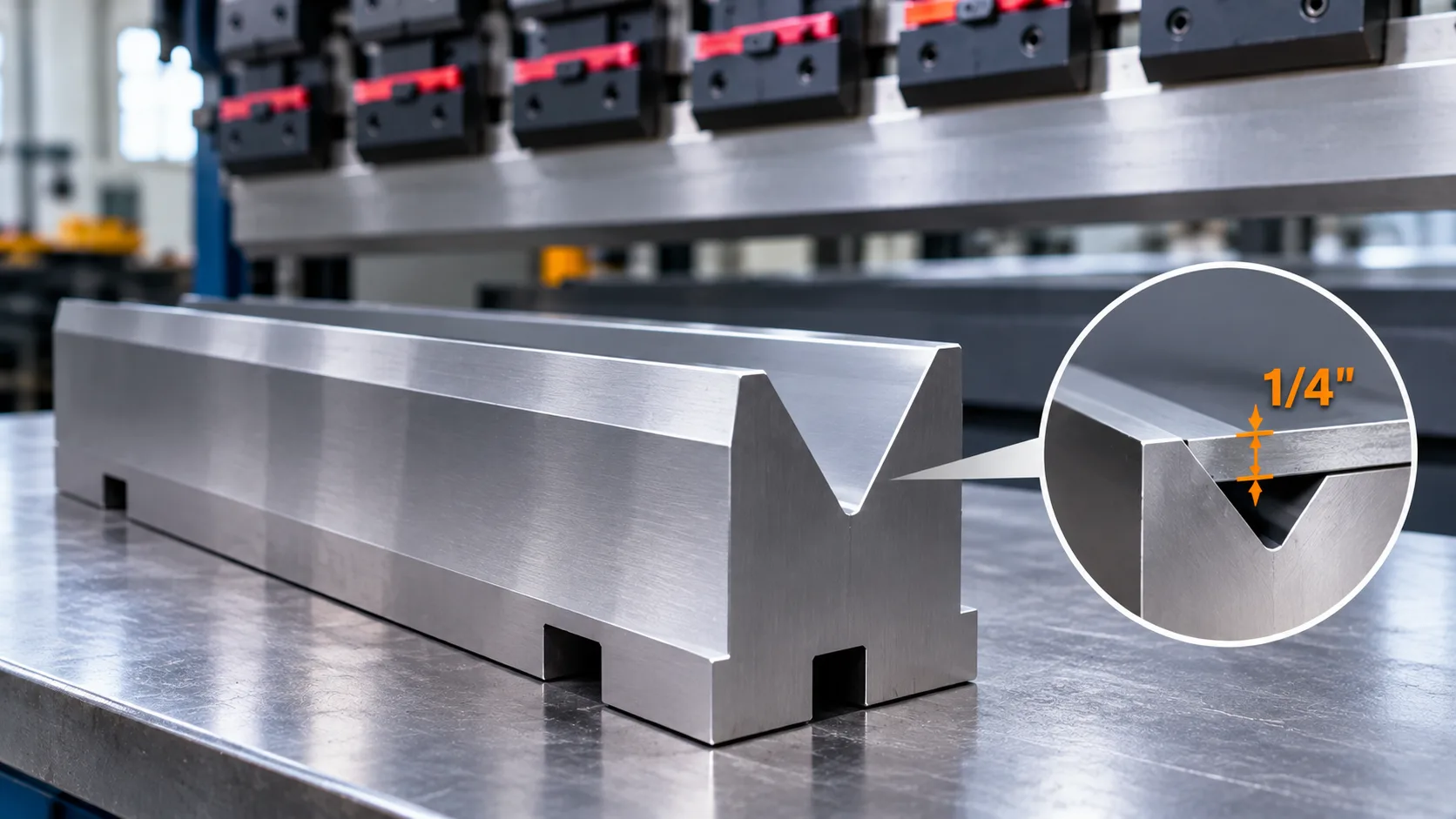
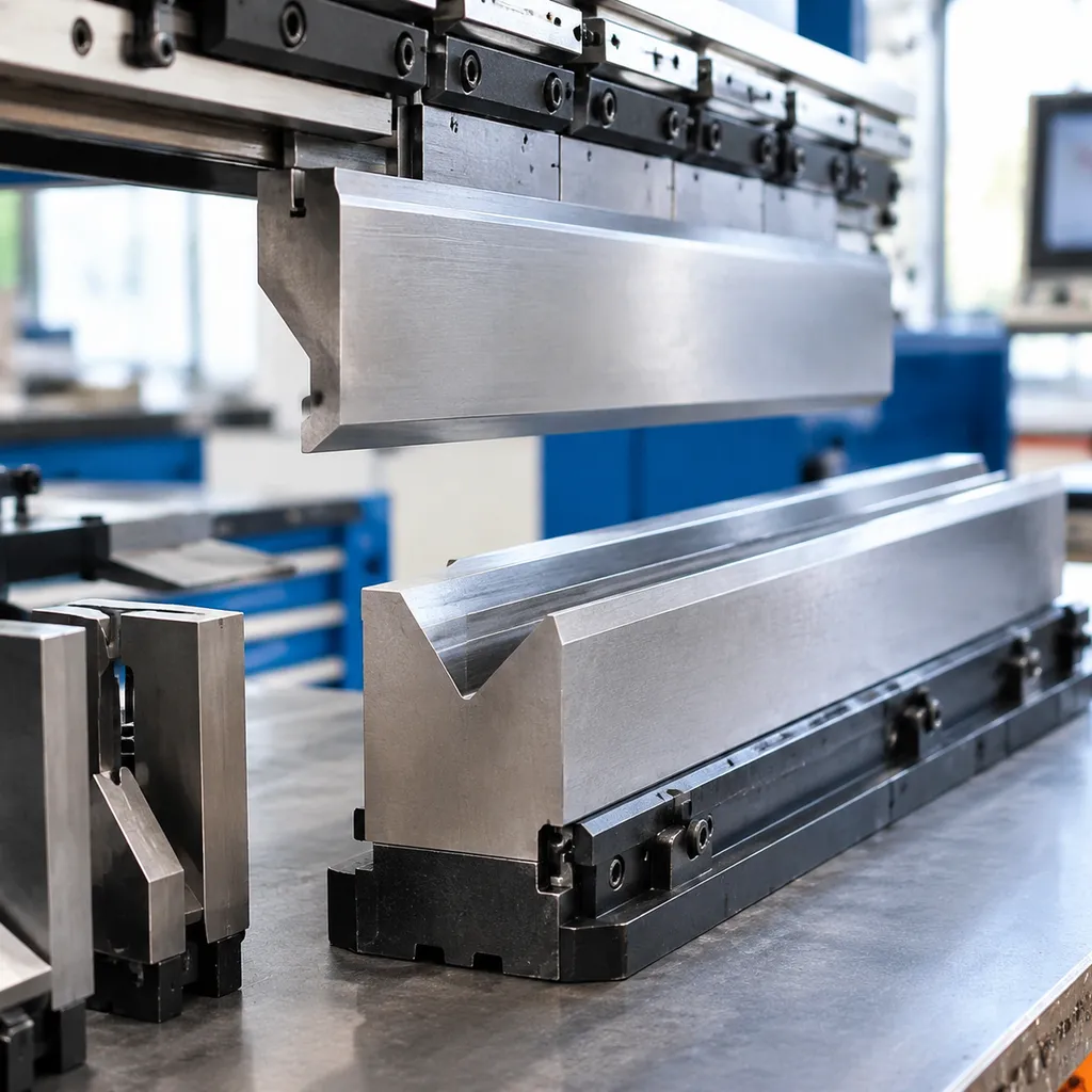
The press brake v die opening (dimension V) is the distance between the two top shoulder radii of the bottom die. It is a linear dimension independent of the die angle.
- V-Opening Width (V): Measures the top span across the die groove. This value determines natural inside bend radii, required bending force, and minimum flange capabilities.
- Die Angle: The included taper of the pocket (typically 85°, 88°, or 90° for standard bending, down to 30° for acute air bending). This geometry allows room for material springback compensation without bottoming out.
| Parameter | Function | Primary Impact |
|---|---|---|
| V-Die Opening (V) | Top shoulder-to-shoulder width | Natural inside radius, tonnage requirements, minimum flange |
| Die Angle | Pocket slope profile | Springback clearance, maximum achievable angle |
Physical Mechanics of Sheet Support in Air Bending
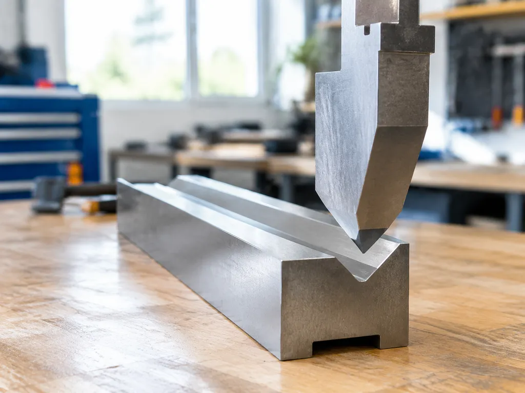
In air bending, the material does not touch the bottom of the V-groove. The sheet rests strictly on two contact points: the die shoulder radii.
- The punch contacts the top surface of the plate along the center axis.
- The material bridges across the press brake v die opening, turning the process into a three-point beam deflection.
- The shoulder radius acts as a fulcrum. As the punch descends, the material slides inward over these radii while yielding in tension on the outer surface and compression on the inner surface.
- The span of the opening governs how much leverage the punch exerts over the sheet metal thickness.
Consequences of Miscalculating the V-Opening
Mismatched V-die selection causes structural damage to tooling and produces out-of-tolerance components.
- Severe Machine Overload: Dropping the V-width below proper ratios spikes the required bending force per meter exponentially. This risks blowing hydraulic seals, cracking standard 42CrMo tooling shoulders, and permanently deflecting the press brake bed.
- Part Geometry Distortion: An oversized opening causes uncontrolled material draw, creates excessive inside radii, and drops the edge of short flanges directly into the pocket.
- Surface Fractures and Coining Marks: A die opening that is too narrow forces excessive friction across the die shoulder radii, leaving heavy tool gouges on the outside face and tearing high-tensile materials along the bend line.
The Core Rule: How to Calculate the Correct V-Die Opening
When calculating a press brake v die opening, we rely on the industry-standard Rule of 8 as our baseline. Under normal air bending conditions for mild steel, the formula is straightforward:
V = 8 × t (where V is the die opening width and t is the material thickness).
Using an opening eight times the sheet thickness produces an inside bend radius roughly equal to the metal thickness while keeping tonnage within standard working limits. For a complete breakdown of ratios across standard setups, check our press brake die opening guide and selection tips to match tooling geometry with your specific machine capacity.
Thickness Thresholds and Multipliers
The 8x ratio is a reliable baseline, but plate thickness dictates when you must adjust the multiplier:
- Sheet Metal (Under 3 mm / 0.118 in): Use 6x to 8x thickness. A tighter 6x opening holds tighter radii and shorter flanges on precision electronic enclosures, provided your tooling load limits allow it.
- Medium Plate (3 mm to 8 mm / 0.118 to 0.315 in): Stick to the standard 8x thickness. This balances required tonnage with part consistency.
- Heavy Plate (Over 8 mm / 0.315 in): Step up to 10x to 12x thickness. Heavy plate demands larger openings to reduce the extreme tonnage required and to prevent localized fracture along the bend line.
Material-Specific Compensations
Different metals behave differently under bending pressure. We adjust the press brake v die opening based on tensile strength, ductility, and springback characteristics:
- Mild Steel (Cold Rolled / A36): Runs perfectly on the standard 8x multiplier. Yield strength is predictable, and cracking risks are minimal under normal conditions.
- Stainless Steel (304 / 316): With roughly 50% higher tensile strength than mild steel, work-hardening occurs instantly. We recommend opening up to 10x to 12x thickness to lower the tonnage load and counter aggressive springback.
- Aluminum (5052-H32 vs. 6061-T6): Soft aluminum (5052) handles tighter 6x openings cleanly. Tempered structural aluminum (6061-T6), however, cracks easily along the grain; increase your opening to 10x to 12x to form a wider natural radius and prevent outer-flange splitting.
- High-Strength Steels (Hardox, Weldox, Domex): Yield strengths frequently exceed 700 MPa. We run these on 10x to 14x openings. Squeezing high-tensile plate into a narrow V-die will overload your press brake, ruin the die shoulders, or snap the plate along the bend line.
Mathematical Impact: How V-Opening Governs Bend Geometry
Changing your press brake v die opening fundamentally alters the physics of the bend. When air bending, the die width directly dictates three non-negotiable parameters: inside radius, minimum flange width, and forming tonnage. Misjudging these relationships ruins part tolerances and risks equipment failure.
Natural Inside Bend Radius and the 16 Percent Rule
In air bending, the punch nose does not create the inside bend radius unless the punch nose radius is larger than the naturally formed profile. Instead, the inside bend radius forms naturally across the span of the die shoulders.
- The 16% Rule: For standard mild steel, the natural inside radius equals roughly 15% to 17% of the bottom die width (commonly calculated as Inside Radius = V / 6).
- Material Variations: Softer aluminum forms a tighter natural radius at roughly 12% to 14% of the V-width, while stainless steel yields a larger radius near 18% to 20% due to higher yield strength and springback.
- Punch Pairing: To avoid altering this natural dynamic or causing premature coining, ensure you are selecting the right press brake punch radius that matches or slightly undercuts the natural air bend radius.
Minimum Flange Length and Sheet Support Limits
A bend requires continuous structural support across both die shoulders throughout the entire stroke. If a flange is too short, the edge slips into the V-groove before bottom dead center, leading to an incomplete bend, part deformation, or dropped stock.
- Minimum Flange Formula: Minimum Flange = 0.7 × V
- Practical Limit: For acute or specialized dies, you can occasionally drop to 0.6 × V, but standard 85° and 90° dies require at least 70% of the opening to safely span the shoulder gap.
- The Takeaway: When tight blueprinted flanges demand a smaller die, you must evaluate whether your sheet thickness permits narrowing the die without overloading the tool.
Bending Tonnage and the Inverse Proportion Law
Bending resistance scales in direct, inverse proportion to the die opening. When you cut your press brake v die opening in half, you double the required bending force per meter.
- The Inverse Law: Halving the die width drops the leverage of the workpiece, requiring twice the ram pressure to achieve the same degree of bend.
- Tonnage Formula: Tonnage (tons/meter) = (1.42 × Material Tensile Strength × Sheet Thickness²) / V-Die Opening
- Machine Safety: Forcing thick stock into a narrow opening quickly spikes local loads beyond the manufacturer's maximum tons-per-meter threshold. Consult our comprehensive press brake V die chart and tonnage guide to verify that your selected opening keeps total machine load safely within operational limits.
Diagnostic Matrix: Symptoms of an Incorrect V-Die Selection
| Symptom / Defect | Root Cause | Immediate Mechanical Risk | Corrective Action |
|---|---|---|---|
| Cracked outer bend radius | V-opening is too narrow | Sheet metal fracture, weakened structural integrity | Increase V-die width to reduce strain on outer fibers |
| Tooling shoulder gouging | V-opening is too narrow | Tool shoulder wear, severe sheet marking | Step up to an 8x or 10x ratio; check die shoulder radius |
| Machine tonnage overload | V-opening is too narrow | Blown hydraulic seals, cracked bed, broken tooling | Enlarge opening to cut required bending force in half |
| Flange slipping into V-pocket | V-opening is too wide | Asymmetrical bend, inaccurate flange height | Use a smaller V-die that supports the minimum flange width |
| Wild angular variations | V-opening is too wide | Uncontrolled material springback, erratic bend angles | Decrease die opening to achieve stable three-point air bending |
| Oversized inside bend radius | V-opening is too wide | Part interference during assembly, blueprint rejection | Match opening width to roughly 6x the desired inside radius |
Identifying Issues When the V-Opening Is Too Narrow
Choking the metal into a narrow slot concentrates excessive tonnage across a tiny surface area. When running our shop floor evaluations, these are the immediate red flags of an undersized V-groove:
- Severe Coining and Surface Scratches: Deep indentations appear along both shoulder contact points. If the opening is undersized, the punch forces the sheet to drag violently against the tooling shoulders rather than rolling smoothly into the air-bend pocket.
- Exceeded Tooling Load Limits: Bending force spikes exponentially. Dropping your V-die width by half doubles the required bend force, putting your press brake tonnage limits and our hardened press brake dies at severe risk of fracture.
- Material Cracking Along the Bend Line: Bending high-tensile steels or hard aluminum alloys over an undersized die pinches the outer bend radius too tightly, forcing tensile failure and splitting the grain.
Identifying Issues When the V-Opening Is Too Wide
Selecting an oversized V-opening to reduce tonnage introduces geometric instability and parts that fail quality inspections:
- Flange Edge Drop-Off: If a short flange does not reach across at least 70% of the die shoulder opening, the sheet slips down into the pocket during the stroke. This produces deformed parts, tapers, and dangerous workpiece kick-up.
- Ballooning Inside Radius ($R_i$): In air bending, the inside radius forms naturally at roughly 16% of the die opening ($V / 6$). A wider opening produces an unexpectedly large inside radius regardless of your punch tip radius, creating parts that clash with downstream assembly components.
- Unpredictable Springback: A loose, wide V-cavity provides insufficient localized yield stress. The material flexes elastically instead of setting into plastic deformation, causing extreme angular variations across different sheets in the same batch. Overworking the machine to compensate accelerates premature wear, making regular press brake die maintenance mandatory to spot uneven shoulder deterioration before scrap rates climb.
Press Brake Tooling Configurations: Choosing the Right Die Style
Selecting the proper die body style is just as critical as calculating the correct press brake V die opening width. The tool configuration controls machine centerline alignment, setup speeds, and physical clearance for return flanges.
Single-V vs. Double-V Dies for Center Loading
- Single-V Dies: Engineered with a single V-groove centered directly over the tang. This layout delivers optimal tonnage transmission straight down the press brake centerline. We use single-V tooling for narrow punch clearances, acute bottoming, and high-tonnage runs where offset side-loading must be completely eliminated.
- Double-V Dies: Feature two different V-grooves on opposite sides of a single tool body. They reduce tool investment and quicken changeovers between two common gauges (such as 1.5 mm and 3.0 mm sheet). However, operators must verify that the active V-groove aligns precisely with the machine beam centerline to avoid eccentric side loads on the ram guides.
Multi-V Die Blocks for High-Mix Job Shops
Four-way and multi-V die blocks pack multiple opening sizes around a square or rectangular block.
- Best Application: High-mix, low-volume contract shops that constantly switch between light-gauge sheet and heavy plate.
- Operational Advantages: Rotate the block on its bed holder to switch between distinct V-widths in under two minutes without pulling tools off the machine.
- Design Trade-offs: The bulky block profile severely limits clearance for complex part geometries, deep return flanges, and narrow drop-down channels.
Manual vs. CNC Adjustable V-Dies for Heavy Plate
Swapping massive solid V-blocks on thick plate jobs poses severe safety hazards and kills cycle efficiency. Incorporating specialized adjustable press brake dies solves this bottleneck by letting you expand or contract the groove width across a broad range using spacer shims or automated CNC drives.
| Feature | Manual Adjustable V-Die | CNC Motorized Adjustable V-Die |
|---|---|---|
| Adjustment Mechanism | Precision gauge shims or lead screws | CNC-driven servo motors linked to control |
| Opening Range | Typically 25 mm to 300 mm | Typically 50 mm to 400+ mm |
| Changeover Time | 5 to 15 minutes | Under 30 seconds via program call |
| Ideal Production Environment | Heavy fabrication, structural chassis | Automated cells, armored plate, pole forming |
Precision-Ground vs. Planed Tooling: Wear and Repeatability
The manufacturing process of the die body directly dictates how long your press brake V die opening holds its dimensional integrity:
- Planed Tooling: Machined on traditional shapers or milling machines with standard tolerances (typically ±0.05 mm to ±0.1 mm). Planed dies require manual shimming across the bed to eliminate angular variance. Shoulder wear accelerates rapidly under heavy cycles, widening the effective opening and destabilizing bend angles.
- Precision-Ground Tooling: Finished on CNC profile grinders to critical tolerances (±0.01 mm). The V-groove shoulders undergo localized deep-case induction hardening (56–60 HRC). This keeps the shoulder radius from breaking down under extreme contact stress, ensuring absolute bend-to-bend angle repeatability and constant friction characteristics across the entire length of the bed.
Engineering Reference: Standard V-Die Selection Chart
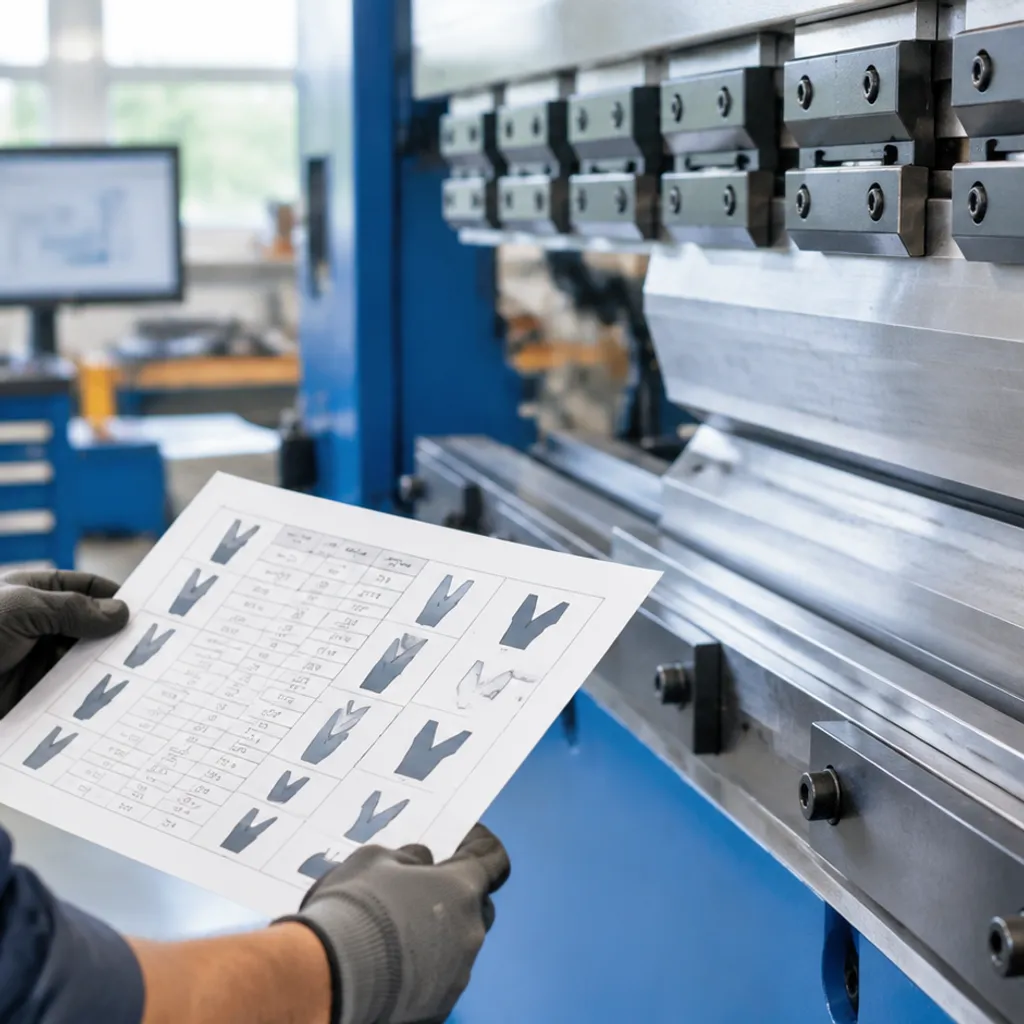
To eliminate guesswork at the machine, we rely on a standardized selection matrix for air bending. Choosing the right press brake v die opening balances tonnage load against inside radius accuracy and prevents premature tool wear.
The baseline values below apply to standard mild steel with an average tensile strength of 420 to 450 MPa. For deeper layouts and profile clearances, reference our comprehensive press brake die size chart and dimensions guide before loading your tooling rack.
| Material Thickness ($t$) | Recommended V-Opening ($V$) | Inside Radius ($R_i$) | Minimum Flange ($b_{\min}$) | Approx. Tonnage per Meter |
|---|---|---|---|---|
| 0.8 mm | 6 mm | 1.0 mm | 4.2 mm | 70 kN / 7 t |
| 1.0 mm | 8 mm | 1.3 mm | 5.5 mm | 80 kN / 8 t |
| 1.5 mm | 12 mm | 2.0 mm | 8.5 mm | 110 kN / 11 t |
| 2.0 mm | 16 mm | 2.6 mm | 11.2 mm | 145 kN / 14.5 t |
| 2.5 mm | 20 mm | 3.3 mm | 14.0 mm | 180 kN / 18 t |
| 3.0 mm | 24 mm | 4.0 mm | 16.8 mm | 220 kN / 22 t |
| 4.0 mm | 32 mm | 5.3 mm | 22.4 mm | 290 kN / 29 t |
| 5.0 mm | 40 mm | 6.7 mm | 28.0 mm | 360 kN / 36 t |
| 6.0 mm | 50 mm | 8.3 mm | 35.0 mm | 440 kN / 44 t |
| 8.0 mm | 64 mm | 10.7 mm | 45.0 mm | 580 kN / 58 t |
| 10.0 mm | 80 mm | 13.3 mm | 56.0 mm | 720 kN / 72 t |
| 12.0 mm | 100 mm | 16.7 mm | 70.0 mm | 870 kN / 87 t |
Quick Correction Factors for Other Alloys
When shifting away from standard carbon steel, multiply the calculated tonnage per meter to avoid exceeding the rated safe working load of your tooling shoulders:
- Stainless Steel (304 / 316): Multiply tonnage values by 1.4 to 1.6. Increase the standard V-opening to roughly 10x thickness to offset severe work-hardening and excessive springback.
- Aluminum (Soft to Half-Hard): Multiply tonnage values by 0.5 to 0.6. A tighter 6x opening can often be used for sharp aesthetic lines without overloading the brake.
- High-Strength Alloys (e.g., Hardox, Strenx): Multiply baseline values by 2.0 or higher. Always expand your opening to 10x–12x thickness to protect structural grain integrity and prevent edge fracturing.
Industrial Tooling Solutions by CAMT
We manufacture precision-engineered press brake tooling designed to eliminate deflection and maintain exact bend profiles across high-volume production runs. When your tolerances depend on consistent sheet positioning, the mechanical integrity of your die shoulders makes all the difference.
- CNC 42CrMo Tooling Profiles: We machine our dies from high-grade 42CrMo alloy steel, deep-hardening critical wear surfaces up to 52–56 HRC. This keeps your press brake v die opening from washing out or galling under intense, localized bending forces.
- Modular Segmented V-Dies: To speed up changeovers and simplify staged setups, we supply precision-ground, segmented tooling compatible with American and European tooling standards, as well as Wila-Trumpf style clamping systems. Every segment is matched to guarantee uniform shut height across the entire bed length.
- Heavy Plate Variable Platforms: Eliminating crane handling and frequent block swaps on thick plate runs, our adjustable press brake die platforms let operators alter the V-width mechanically or via CNC drives to handle high-tensile structural components on demand.
Practical Checklist: 5-Step SOP for Selecting a V-Die on the Shop Floor
Setting up a job properly prevents broken tooling, damaged backgauges, and scrapped parts. Follow this direct 5-step standard operating procedure to validate your setup before striking your first bend.
Step 1: Measure Material Thickness and Check Yield Strength
Never trust the nominal sheet label.
Use a calibrated caliper or micrometer to measure the exact sheet thickness ($t$) across multiple spots.
Confirm material grade. Stainless steel and high-tensile alloys require wider die openings and extra tonnage allowances compared to standard mild steel or aluminum.
Step 2: Calculate Target Press Brake V Die Opening
Apply your base multiplier to select the right channel width:
Run the standard formula: V = 8 × t for standard cold-rolled mild steel between 3 mm and 8 mm.
Drop down to V = 6 to 8 × t for thin sheet under 3 mm when tight radii are mandatory.
Step up to V = 10 to 12 × t for heavy plate to eliminate part cracking and lower required tonnage.
Step 3: Validate Minimum Flange and Profile Clearance
Ensure the cut blank physically spans across the V-groove shoulders throughout the entire bending stroke:
Confirm that your minimum flange dimension exceeds 0.7 × V. If the leg is shorter than this threshold, the edge will slip into the die pocket during forming.
Check profile interference against punch and die geometry. Reviewing a detailed press brake die clearance guide for better bending ensures your return flanges and deep channels clear the die shoulders without collision.
Step 4: Run Tonnage Load and Force Limit Checks
Calculate the required bending force per meter before loading the program:
Determine whether the calculated tonnage stays well within both machine capacity and the specific load limit rating stamped on your die section.
Remember the inverse proportion law: narrowing your press brake v die opening by half doubles the required bending force. If the force nears tooling yield limits, immediately step up to the next wider V-die opening size.
Step 5: Verify Alignment, Shoulder Condition, and Test Bend
Complete final machine checks before running production:
Center the upper punch precisely over the V-groove centerline to prevent side-thrust damage to the ram guides.
Inspect shoulder radii for galling, uneven wear, or micro-cracks. If severe geometric restrictions or step bends interfere with standard tools, switch to specialized press brake die types explained for better metal bending.
Execute a test bend on scrap stock, measure the resulting inside bend radius and angle, and fine-tune your backgauge depth accordingly.
Frequently Asked Questions About Press Brake V Die Opening
Can I Bend Thin Material on an Oversized V-Die?
Yes, but we rarely recommend it if you care about tight tolerances. When you run thin gauge sheet on an oversized press brake v die opening, two distinct issues occur immediately:
- Massive Inside Radius: In air bending, the inside bend radius scales to roughly 16% of the die opening width. If you run 1 mm mild steel across a 16 mm V-opening instead of an 8 mm die, your inside radius doubles from approximately 1.3 mm to 2.5 mm.
- Severe Springback Inconsistency: Excess clearance allows the sheet to float across the shoulders before drawing down, leading to angular deviation across the bend length.
- Minimum Flange Drop-Off: Short flanges will slip straight into the pocket instead of bridging the die shoulders.
If your print allows a larger radius and you have sufficient flange length, it works in a pinch without damaging the tooling. For production runs requiring blueprint accuracy, we always switch to a matched precision press brake V die for accurate bending sized specifically to the sheet thickness.
How Do I Choose a V-Die for Bottoming or Coining?
Bottoming and coining do not follow the standard 8x air bending rule. Because these methods force the sheet to conform directly to the punch tip and die walls, the press brake v die opening must be tighter.
| Bending Method | Typical V-Opening Ratio | Inside Radius Determinant | Tonnage Requirement |
|---|---|---|---|
| Air Bending | 6x to 12x sheet thickness | ~16% of V-opening width | Baseline (Lowest) |
| Bottoming | 5x to 6x sheet thickness | Mirrors punch tip radius | 3x to 5x higher than air bending |
| Coining | 4x to 5x sheet thickness | Exact stamp of punch tip | 5x to 8x higher than air bending |
When bottoming, you drop the opening down to roughly 5 to 6 times material thickness. This forces the punch nose to bottom out against the material inside the V-groove. Warning: Your bending tonnage spikes exponentially. Always verify that your press brake bed and tooling can handle the load before bottoming on narrow die widths.
How Does Die Shoulder Radius Impact the Effective Opening?
The shoulder radius on the entry edges of your V-groove directly alters how the material enters the die cavity.
- Small Shoulder Radii: Sharp shoulders dig into the workpiece, increasing drag, creating cosmetic tooling marks, and artificially increasing the required tonnage.
- Large Shoulder Radii: Generously rounded shoulders allow the material to slide smoothly into the die pocket. However, a large radius shortens the flat span between the shoulders, reducing the true mechanical opening width and requiring slightly longer minimum flange lengths to avoid falling in.
- Shoulder Wear: Over time, heavy production wears down these shoulder profiles unevenly. When dies wear out, the effective opening widens, resulting in inconsistent bend angles and radius creep across standard production batches. For shops running varied setups, a multi-bend press brake die for multi-V material bending maintains uniform shoulder profiles across multiple opening options.