
What Is Press Brake Die Opening and Why Does It Matter?
Why do some sheet metal parts come off the machine with cracked outer bends or inaccurate flange lengths? In our daily shop floor experience, the root cause is almost always an incorrect press brake die opening. Choosing the right lower tool is not guesswork; it is the foundation of accurate, safe, and repeatable metal forming.
Definition and Geometry of the V-Die Opening Width
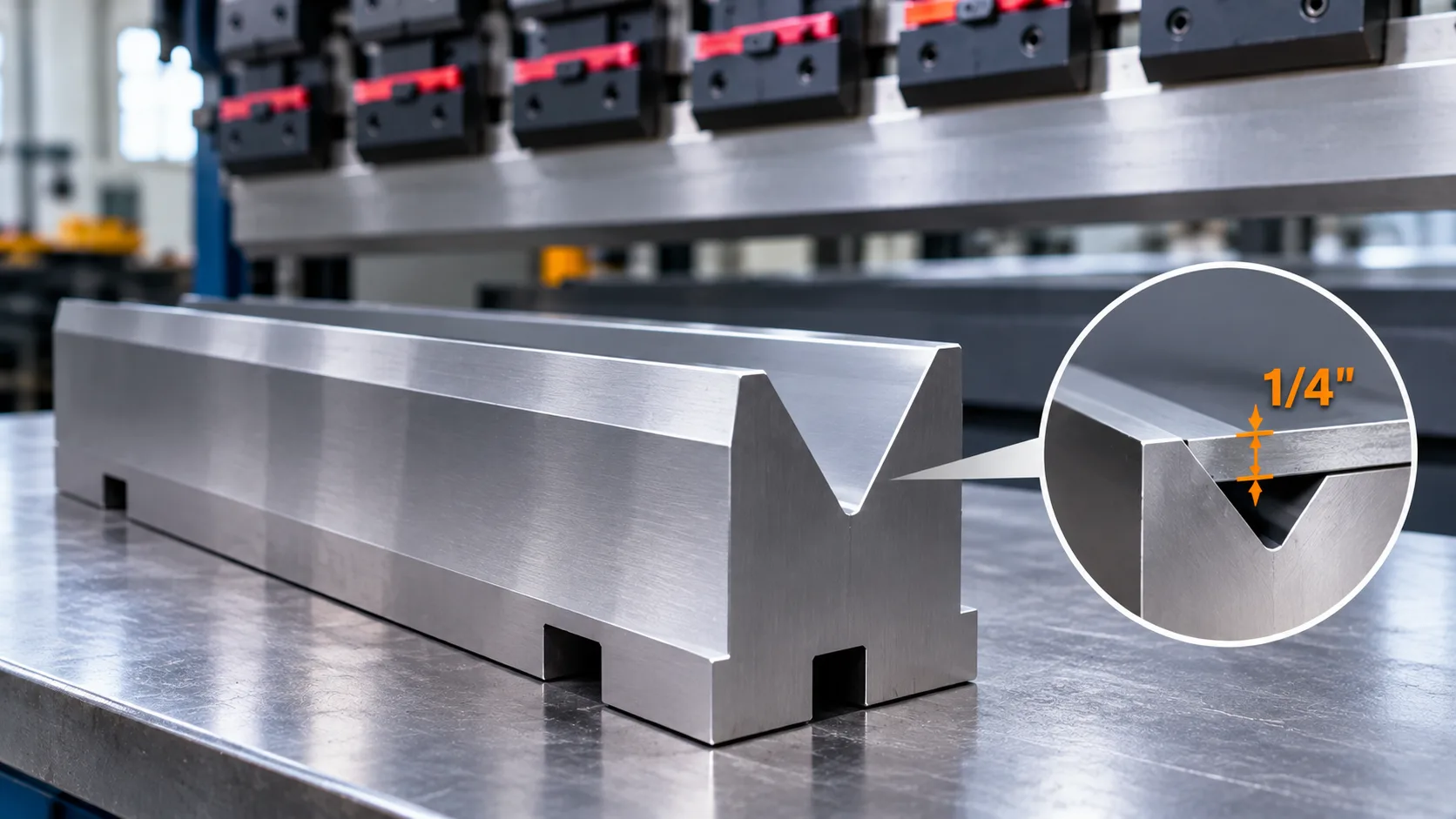
When we talk about the press brake die opening (commonly referred to as the V-width), we mean the exact horizontal distance measured across the top of the V-groove from shoulder to shoulder.
- Measurement Point: It is strictly the span between the two tangent points where the flat sheet metal first contacts the top edges of the lower die, before the die shoulder radius transitions into the angled V-walls.
- Contact Geometry: During a bend, the sheet metal bridges this gap, supported only by the two top edges of the die opening.
How Die Opening Dictates Inside Bend Radius in Air Bending
One of the biggest misconceptions we see in fabrication shops is that the punch tip radius determines the part's inside radius. In standard air bending, the air bending die width dictates the inside bend radius (IR)—not the punch.
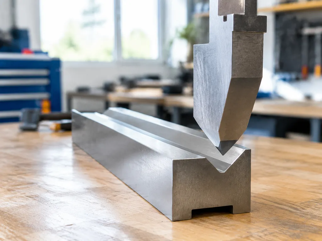
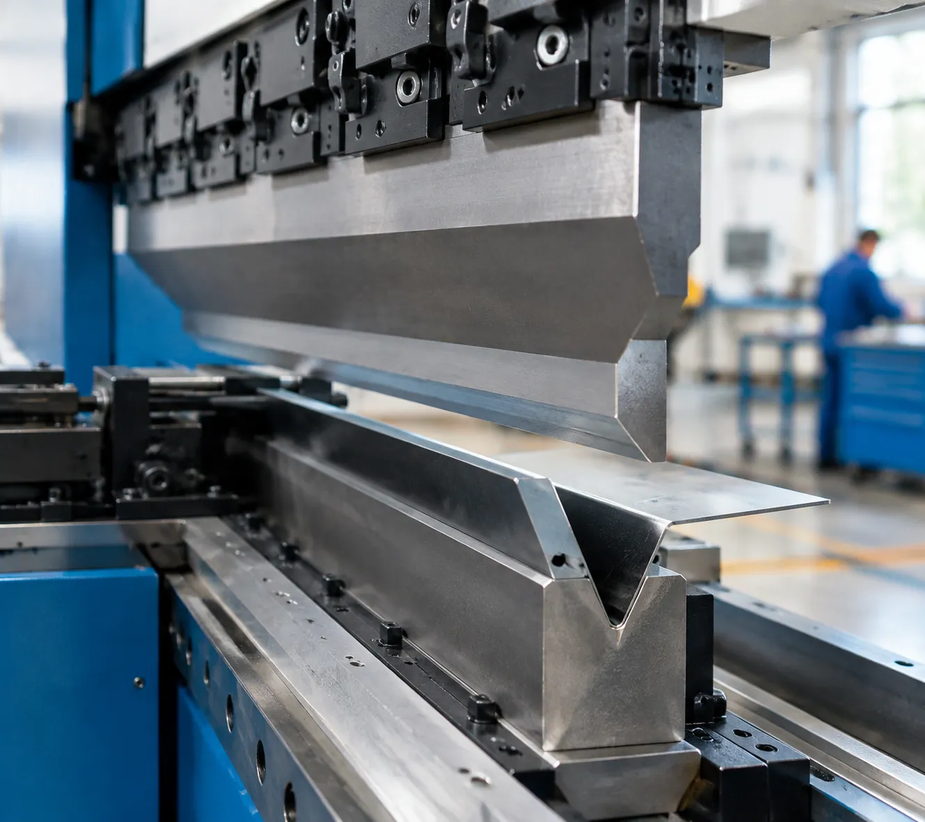
- Natural Forming: As the upper punch pushes the sheet into the V-opening, the suspended material naturally forms a parabolic curve across the gap.
- Direct Correlation: A wider press brake die opening creates a larger inside bend radius, while a narrower opening forces a tighter radius.
- Bend Allowance Impact: Because the V-die controls the radius, changing your bottom die directly alters your sheet metal bend allowance and flat pattern layout.
The Engineering Trade-Off: Tonnage, Bend Radius, and Minimum Flange Length
Effective press brake tooling selection requires balancing three competing physical forces. Whenever we change the V-die width on the shop floor, we immediately trigger a mechanical trade-off:
| V-Die Adjustment | Bending Tonnage | Inside Bend Radius (IR) | Minimum Flange Length |
|---|---|---|---|
| Narrower V-Opening | Increases (Higher risk of tool overload) | Decreases (Tighter, sharper bend) | Decreases (Allows shorter flanges) |
| Wider V-Opening | Decreases (Less wear on machine and tools) | Increases (Larger, sweeping radius) | Increases (Requires longer flanges to bridge the gap) |
- Bending Tonnage: Think of the V-opening as a lever. A narrower opening shortens the lever arm, causing the required bending tonnage calculation to spike dramatically. A wider opening reduces tonnage, protecting your machine and preventing press brake tool deflection and wear.
- Minimum Flange Length: The sheet metal must continuously span across both die shoulders throughout the entire stroke. If you select a wide die to save tonnage, your minimum flange length increases—meaning shorter flanges will simply drop into the V-groove and ruin the part.
Press Brake Die Opening Sizing Rules and Thickness Ratios
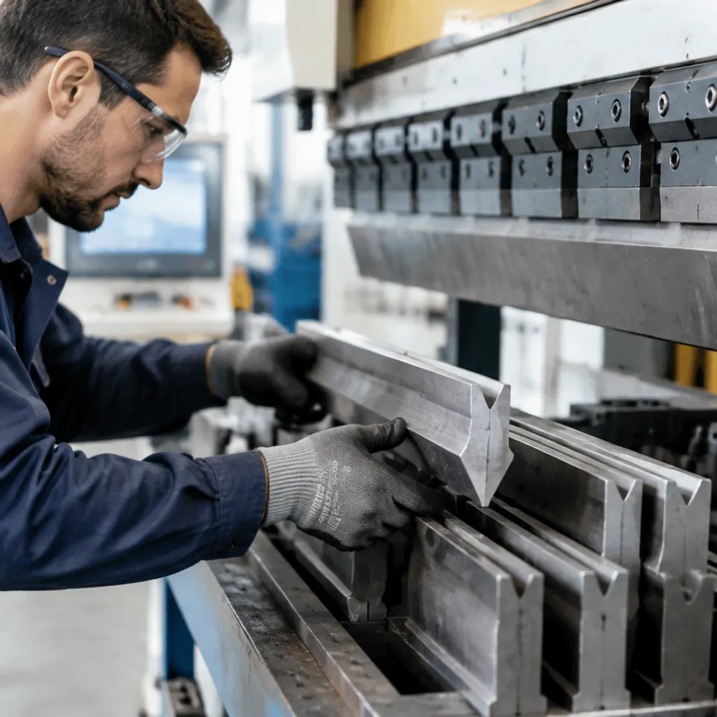
Getting your tooling setup right starts with matching your sheet thickness to the proper die width. If you grab the wrong bottom die, you either blow past your machine's tonnage limits or end up with an out-of-spec bend radius that ruins the part. Here is how we dial in the correct ratio on the shop floor every single day.
The Universal 8x Rule of Thumb for Mild Steel
For everyday air bending of mild steel, the industry standard is the 8x rule of thumb. This means your press brake die opening should equal eight times the material thickness:
- Formula: V-Opening = 8 × Material Thickness (t)
When you run an 8x ratio on 16-gauge through 1/4-inch mild steel, the material forms a natural inside bend radius (IR) roughly equal to the sheet thickness (approximately 16% of the V-opening). It strikes the ideal balance across the board:
Keeps required bending tonnage well within safe machine limits.
Delivers a clean, predictable inside radius without cracking the outer surface.
Maintains a practical minimum flange length that won't fall down into the die pocket.
When to Use a 6x Die Ratio for Thin Sheets and Sharp Radii
We drop down to a 6x die ratio when we need to bend short flanges or form tighter inside radii on thin gauge sheets (typically 1.2 mm / 18 gauge and thinner).
- Where it works best: Precision electrical enclosures, thin aluminum brackets, and parts with tight print callouts where flange length is severely restricted.
- The trade-off: Narrowing the air bending die width dramatically increases your tonnage load per foot—often by 30% to 35% compared to an 8x setup. It also increases tool wear and leaves deeper contact marks on the workpiece. If you go this route, check your punch tip radius and tool ratings first.
When to Expand to 10x or 12x for Stainless Steel and Heavy Plate
As sheet thickness increases or material tensile strength climbs, you must open the bottom die wider. We move to a 10x or 12x die ratio for heavy plate (6 mm / 1/4-inch and above) and high-yield metals like 304/316 stainless steel.
- Stainless steel: Higher tensile strength requires significantly more force to yield. Widening the press brake die opening to 10x drops the required tonnage back down to manageable levels and protects the machine ram.
- Heavy plate & high-strength alloys: Bending plate through a narrow die creates extreme localized strain, causing parts to split or crack along the outer bend line. Expanding to 10x–12x allows the plate to form a gentler radius and prevents structural failure.
When forming tougher materials or thicker plate, pairing the right V-opening with dedicated press brake die sets for sale high strength steel ensures the tool shoulders withstand the massive lateral loads without chipping or deforming.
Material Thickness to V-Die Selection Matrix
Use this quick-reference guide to select the starting sheet metal thickness to V die ratio based on your material grade and gauge:
| Material Type | Thickness Range | Recommended Ratio | Target V-Die Opening Width | Primary Goal |
|---|---|---|---|---|
| Thin Mild Steel / Soft Aluminum | Under 1.0 mm (Under 20 ga) | 6x | 6 × t | Supports short flanges; tighter radius |
| Standard Mild Steel (Cold Rolled/A36) | 1.0 mm – 6.0 mm (18 ga – 1/4") | 8x | 8 × t | Optimal balance of tonnage, radius, and tool life |
| Stainless Steel (300 & 400 Series) | 1.0 mm – 4.0 mm (18 ga – 8 ga) | 10x | 10 × t | Tonnage compensation; reduces surface marring |
| Heavy Plate Steel | 6.0 mm – 12.0 mm (1/4" – 1/2") | 10x to 12x | 10x – 12x × t | Prevents outer fracture; respects machine tonnage |
| High-Strength / Hardened Alloys | All thicknesses | 12x+ | 12 × t | Eliminates bend cracking; controls severe springback |
Engineering Formulas for Press Brake Die Selection
Inside Bend Radius: The 16 Percent Air Bending Rule
In air bending, the punch tip radius does not establish the finished inside bend radius (IR). Instead, the press brake die opening dictates the radius as the sheet metal flows over the die shoulders.
For standard mild steel with 60,000 PSI tensile strength, calculate inside radius using the 16 percent rule:
- Formula: Inside Bend Radius (IR) = V-Die Opening Width × 0.16
For example, when running a 50 mm V-opening on mild steel, the natural inside radius forms at roughly 8 mm. When switching materials, adjust the factor:
- Soft Aluminum: 12% to 14% of die width
- Mild Steel: 15% to 17% of die width
- 304 Stainless Steel: 20% to 22% of die width
Formulas for Minimum Flange Length to Prevent Part Drop-Off
A short flange will slip into the V-groove if the sheet edge cannot span the die entry shoulders during the stroke. To avoid part distortion or drop-off, apply this basic rule:
- Formula: Minimum Flange Length = Press Brake Die Opening × 0.7
If you are using a 32 mm die opening, the minimum recommended external flange is roughly 22.4 mm. When a part print demands a shorter flange, switch to an acute tooling setup or review a dedicated press brake die selection guide for precise bending to find an appropriate narrower profile.
Calculating Bending Tonnage Based on Die Opening Width
Bending tonnage requirements are inversely proportional to the die opening width. Doubling your V-opening cuts the required bending load by half, reducing wear on your machine.
Use this shop-floor tonnage estimate for mild steel:
- Metric Formula: Tonnage (Metric Tons/m) = (650 × Material Thickness² in mm) / V-Die Opening in mm
- Imperial Formula: Tonnage (US Tons/ft) = (575 × Material Thickness² in inches) / V-Die Opening in inches
For high-strength materials, apply a material multiplier:
Stainless Steel: Multiply tonnage by 1.5
High-Strength Alloys: Multiply tonnage by 1.8 to 2.0
Aluminum Alloys: Multiply tonnage by 0.5 to 0.6
Preventing Machine Overload and Press Brake Tool Deflection
Choosing an undersized V-die to produce a sharp radius is the fastest way to crack tooling or damage the press brake hydraulic system. Keep these shop-floor safety checks in mind:
- Check Max Load per Meter: Tooling manufacturers stamp maximum load ratings (tons/meter or tons/foot) on the die body. Never run a narrow die near its breaking point.
- Avoid Ram and Bed Deflection: High tonnage concentrated over a narrow bed area causes machine deflection, which results in parts that are overbent at the ends and underbent in the middle.
- Control Tool Wear: Extreme shoulder pressure from narrow dies creates micro-grooves and shoulder galling, requiring premature tooling replacement.
Press Brake V Opening Reference Chart
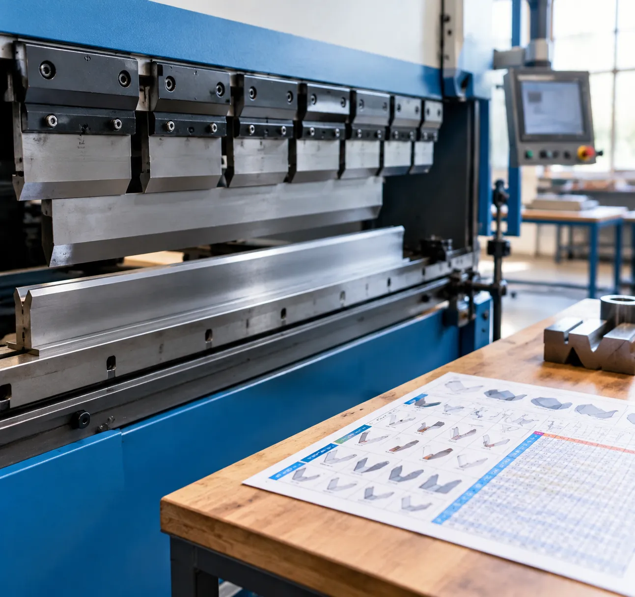
Setting up a job without checking your die dimensions leads to deformed profiles, blown-out tolerances, or damaged tooling. We rely on standardized reference metrics to match sheet thickness with the right die geometry before cycling the ram.
The reference table below establishes our baseline sizing parameters for air bending standard mild steel (tensile strength approximately 450 N/mm²). Use this data alongside our detailed press brake V die chart and tonnage guide to confirm setup parameters before striking your first part.
Mild Steel Air Bending Parameters (0.5 mm to 12.0 mm)
| Sheet Thickness (mm) | Recommended V-Opening (mm) | Inside Bend Radius (mm) | Minimum Flange Length (mm) | Required Tonnage (Tons/Meter) |
|---|---|---|---|---|
| 0.5 | 4 | 0.7 | 2.8 | 4 |
| 0.8 | 6 | 1.0 | 4.2 | 6 |
| 1.0 | 8 | 1.3 | 5.6 | 7 |
| 1.2 | 8 | 1.3 | 5.6 | 9 |
| 1.5 | 12 | 2.0 | 8.5 | 11 |
| 2.0 | 16 | 2.6 | 11.2 | 16 |
| 2.5 | 20 | 3.3 | 14.0 | 20 |
| 3.0 | 24 | 4.0 | 17.0 | 25 |
| 4.0 | 32 | 5.3 | 22.5 | 34 |
| 5.0 | 40 | 6.7 | 28.0 | 42 |
| 6.0 | 50 | 8.3 | 35.0 | 50 |
| 8.0 | 64 | 10.7 | 45.0 | 68 |
| 10.0 | 80 | 13.3 | 56.0 | 85 |
| 12.0 | 100 | 16.7 | 70.0 | 102 |
Essential Setup Considerations
- Tonnage Variations: The values above reflect standard cold-rolled mild steel. When forming stainless steel (304/316), increase tonnage requirements by roughly 50%. For soft aluminum alloys, decrease required tonnage by approximately 50%.
- Flange Fall-Off Risk: Your minimum flange length must safely span the shoulder entry radii of the bottom die. If a flange is shorter than the minimum listed value, the edge will slip into the V-groove before reaching target angle.
- Tooling Limits: Always check actual load requirements against your machine bed limits and tooling load capacities using our European press brake die rating guide for tonnage safety to prevent permanent shoulder deformation.
Common Mistakes in Press Brake Die Opening Sizing
We see it on shop floors every week: an operator needs to bend a bracket and simply grabs whatever bottom die is already sitting in the bed holders to save setup time. Mismatching your sheet thickness to your press brake die opening ruins parts, wrecks tooling, and puts unnecessary strain on your machine.
Consequences of Choosing an Undersized Die Opening
Dropping below the recommended sheet-to-die ratio creates immediate structural and mechanical problems:
- Dangerous tonnage spikes: Bending tonnage is inversely proportional to the die width. Halving your V-opening doubles the force required to make the bend, which drastically accelerates press brake tool deflection and wear or can crack the tooling bed entirely.
- Material cracking along the bend line: An undersized die forces the punch tip to penetrate deeper, driving a sharp inside bend radius into the sheet. High-strength steels and temper-treated alloys will crack or fail along the bend line.
- Severe shoulder marking: Forcing metal into a narrow slot concentrates excessive friction on the shoulders, gouging the external bend surface and ruining parts with cosmetic requirements.
To prevent operators from taking risky shortcuts when switching sheet thicknesses, keeping a 4-way press brake die with multiple V-openings mounted on the bed allows fast indexing to the correct width without manual die changeover delays.
Problems Caused by Running an Oversized V-Die Opening
Going significantly wider than necessary brings its own set of production issues:
- Uncontrolled inside bend radius (IR): In air bending, the inside radius naturally forms at roughly 15% to 17% of the die width. If your die opening is too wide, your inside radius blows out larger than specified on the print, throwing off your flat pattern layout and sheet metal bend allowance.
- Short flange drop-off: Flanges that are shorter than the die shoulder span cannot bridge the gap. Instead of forming cleanly, the material slips directly into the V-groove, resulting in ruined parts and inconsistent bend angles.
- Increased springback and angle drift: A wide opening provides less localized forming pressure, which increases angular springback. This forces operators into deep overbending routines that introduce angle variations across long production runs.
When jobs call for frequent gauge shifts, using a 10-opening press brake die ensures we always have the proper V-opening available to maintain tight radius tolerances and stable flange support.
Bending Workarounds for Non-Standard Applications
When standard rules of thumb clash with real-world part prints, standard setups lead to scrap. We frequently encounter tight cutouts, extreme alloy springback, and tight tolerances that require dialing in the press brake die opening beyond standard charts.
Preventing Flange Distortion Near Holes and Cutouts
Placing cutouts or holes too close to the bend line creates an immediate problem: the edge of the hole falls inside the die shoulder, causing the metal to flare, stretch, or pull out of round.
To eliminate blowout without redesigning the flat pattern:
Drop to a smaller V-die width: A narrower press brake die opening pulls the die shoulder contact points closer to the bend line, keeping the cutout supported on the flat surface of the die during the stroke. Always verify that the increased tonnage remains safely within machine limits.
Use relief cuts: Add laser-cut micro-slits along the bend line near the hole perimeter to relieve tensile stress before the sheet pulls over the die radius.
Switch to mark-free bending: Specialized bottom dies or protective inserts prevent the unsupported edge from dropping prematurely into the V-groove.
Managing High Springback with Acute Tooling
High-strength alloys, temper-grade aluminum, and stainless steel present dramatic springback that standard 85° or 88° dies cannot compensate for in an air bend. If the punch bottoms out against the die walls before reaching the required overbend angle, your final part will remain underbent.
We handle high-yield materials by pairing our target die opening with dedicated acute press brake dies for precision bending. Running 30° or 45° acute V-openings provides the physical clearance needed to stroke deep into the die cavity, overbending the sheet sufficiently so the material rebounds directly to the targeted 90° angle. When sizing an acute die opening, maintain a ratio wide enough to avoid coin-marking while keeping tonnage within machine parameters.
Precision Ground Tooling and Shoulder Radius Consistency
A press brake die opening is only as reliable as its shoulder entry radii. On non-standard or tight-tolerance jobs, inconsistent shoulder geometry causes part-to-part variation along the bend line.
- Friction and flow: As the sheet draws into the V-cavity, it slides directly across the shoulder radii. Uniform, precision-ground shoulders provide identical resistance on both sides, keeping the bend line centered.
- Tonnage spikes: Sharp or worn die shoulders act like knife edges, increasing the required forming tonnage and gouging the workpiece.
- Angle repeatability: Consistent shoulder profiles across the entire length of the tool eliminate localized drag, ensuring angle consistency across long parts.
Step-by-Step Guide to Selecting the Right Press Brake Die Opening
1. Review Part Print Specifications and Radius Tolerances
Before reaching for any tooling, look at the finished drawing:
Inside Bend Radius (IR): In air bending, your V-die width establishes the naturally formed inside radius (typically 15% to 17% of the die opening for mild steel). Match the target IR to the opening that produces it.
Leg Dimensions and Tolerances: Note whether the engineer specified tight angular tolerances or standard commercial prints.
Hole-to-Bend Relief: Identify any cutouts or slots sitting close to the bend line that could distort if the die opening is too wide.
2. Measure Actual Material Gauge and Grain Direction
Never rely on nominal sheet specifications stamped on the pallet. Grab a calibrated micrometer or vernier caliper:
Measure Actual Thickness: Material thickness variations across mill batches alter your tonnage, inside radius, and depth penetration.
Identify Grain Direction: Bending parallel to the grain increases the risk of cracking, requiring a wider die ratio. Bending transverse (across) the grain gives higher ductility and allows tighter V-openings.
3. Select Baseline V-Opening Ratio Based on Alloy
Match your measured sheet thickness to the proper die ratio based on yield strength:
Mild Steel: Use the standard 8x material thickness baseline.
Stainless Steel & High-Strength Alloys: Expand to 10x or 12x to relieve high tonnage and prevent outer-radius fracturing.
Soft Aluminum & Thin Stock: Scale down to 6x if you require a tighter inside bend radius.
Compare your selection against our press brake die size chart and dimensions guide to confirm you are using standardized tooling profiles available in your rack.
4. Verify Minimum Flange Support Across Die Shoulders
Ensure the shortest part flange sits securely across the die shoulders before forming begins:
A flange must extend across the V-opening shoulders by at least 70% to 75% of the total die opening width.
If your flange is shorter than the minimum threshold, it will fall into the V-groove during the stroke, skewing the bend angle and creating a serious safety hazard. If necessary, step down to a smaller V-die or use specialized support tooling.
5. Verify Tonnage Limits Against Machine and Tooling Ratings
Calculate the required bending tonnage per meter (or foot) before clamping your tools:
Calculate required load based on material tensile strength, thickness, and chosen die opening.
Verify that the required tonnage falls well within the press brake’s rated bed limit.
Confirm the load does not exceed the maximum shoulder load rating of the die or the tip limit of the punch.
6. Update CNC Control Bend Allowance and Bend Deduction
Every time you switch to a different press brake die opening, your inside radius changes, shifting the neutral axis (K-factor):
Recalculate your sheet metal bend allowance and bend deduction for the specific die opening width selected.
Enter the updated tooling profile, V-width, punch radius, and bend deduction into the CNC controller.
Run a single test bend on scrap material of the exact same gauge to verify flange dimensions and angle before launching the full run.
| Setup Step | Primary Verification | Shop Floor Check |
|---|---|---|
| 1. Print Review | Target inside bend radius & hole locations | Confirm drawing allows air-bent radius |
| 2. Gauge Check | Actual sheet thickness & grain orientation | Measure using calipers; avoid nominal values |
| 3. Ratio Selection | Alloy-specific die ratio (6x, 8x, 10x, 12x) | Match material yield to appropriate opening |
| 4. Flange Safety | Minimum flange contact length | Confirm part spans shoulders without slipping |
| 5. Load Verification | Tonnage per unit length | Check against machine bed and tool load limits |
| 6. CNC Calibration | Bend deduction and backgauge position | Run a test bend to verify target dimensions |
Frequently Asked Questions About Press Brake Die Opening
Can I Use an 8x Die Ratio for Hardened Aluminum 6061-T6?
Using a standard 8x die opening on Aluminum 6061-T6 almost guarantees outer surface cracking or complete flange failure.
Because T6 temper aluminum has low ductility and high yield strength, the outer fibers cannot stretch around the tight radius naturally formed by an 8x opening. We recommend using a 10x to 12x die ratio instead:
- Relieve surface tension: Expanding the press brake die opening forces a larger natural inside bend radius, preventing the metal from snapping.
- Watch grain direction: Always bend transverse (perpendicular) to the rolling grain whenever possible. If you must bend parallel to the grain, jump to at least a 12x opening.
- Match punch radius: Pair the wider die opening with a punch nose radius that closely mirrors the floating air bend radius to avoid localized stress concentrations.
How Does Changing the Die Opening Affect Bend Deduction and Bend Allowance?
In air bending, the punch nose does not determine your inside bend radius (IR)—the press brake die opening does. Because the inside radius floats to roughly 16% of the die width in mild steel, altering the opening directly shifts your flat blank math:
| Die Opening Change | Inside Radius (IR) | Bend Allowance (BA) | Bend Deduction (BD) | Flat Blank Size |
|---|---|---|---|---|
| Wider V-Opening | Increases | Increases | Increases | Requires smaller flat blank |
| Narrower V-Opening | Decreases | Decreases | Decreases | Requires larger flat blank |
Whenever an operator swaps to a different die size on the floor, you must recalculate the bend deduction in your CNC controller. Leaving the original bend allowance intact while bending over an alternate die opening results in out-of-spec finished flange lengths.
What Is the Difference Between V-Opening Width and Shoulder Entry Radius?
While both dimensions sit at the top of the tool, they serve distinct mechanical purposes during forming:
- V-Opening Width: The horizontal span between the theoretical top intersection points of the V-groove. This width controls the floating inside radius, overall tonnage requirements, and minimum possible flange length.
- Die Shoulder Entry Radius: The rounded curve machined into each top edge where the sheet metal slides downward into the V. A smooth, properly hardened shoulder minimizes drag resistance, prevents material galling, and keeps friction-induced tonnage spikes under control.
Equipping your press with a hardened precision press brake V-die ensures these shoulder radii remain completely uniform from end to end, eliminating inconsistent angular variation along the bend line.
When Should You Choose an Adjustable V-Die Over Standard Fixed Dies?
Fixed V-dies excel at high-volume, repetitive production where you run consistent sheet gauges day in and day out. However, switching tools for varying material thicknesses creates major bottlenecks when forming medium-to-heavy plate.
Choosing an adjustable press brake die is the best operational move when:
- Handling frequent gauge shifts: You can reconfigure the opening width in minutes using shims or motor drives, eliminating heavy crane handling.
- Processing heavy structural plate: Forming high-strength steel plate from 6 mm to 25 mm requires frequent ratio adjustments to avoid cracking while keeping tonnages within machine limits.
- Dialing in custom radii: When tight-tolerance jobs demand a specific inside bend radius that falls between standard modular die sizes, an adjustable system lets you tune the opening width directly to the print.