Mastering your press brake die dimensions and calculating the right V-opening is the difference between a flawless bend and a pile of scrap metal.
In this guide, you'll get access to a complete press brake die size chart and step-by-step sizing rules—from applying the classic 8x rule to calculating exact tonnage requirements and minimum flange lengths. Let’s dive right in.
Core Anatomy of Press Brake Die Dimensions
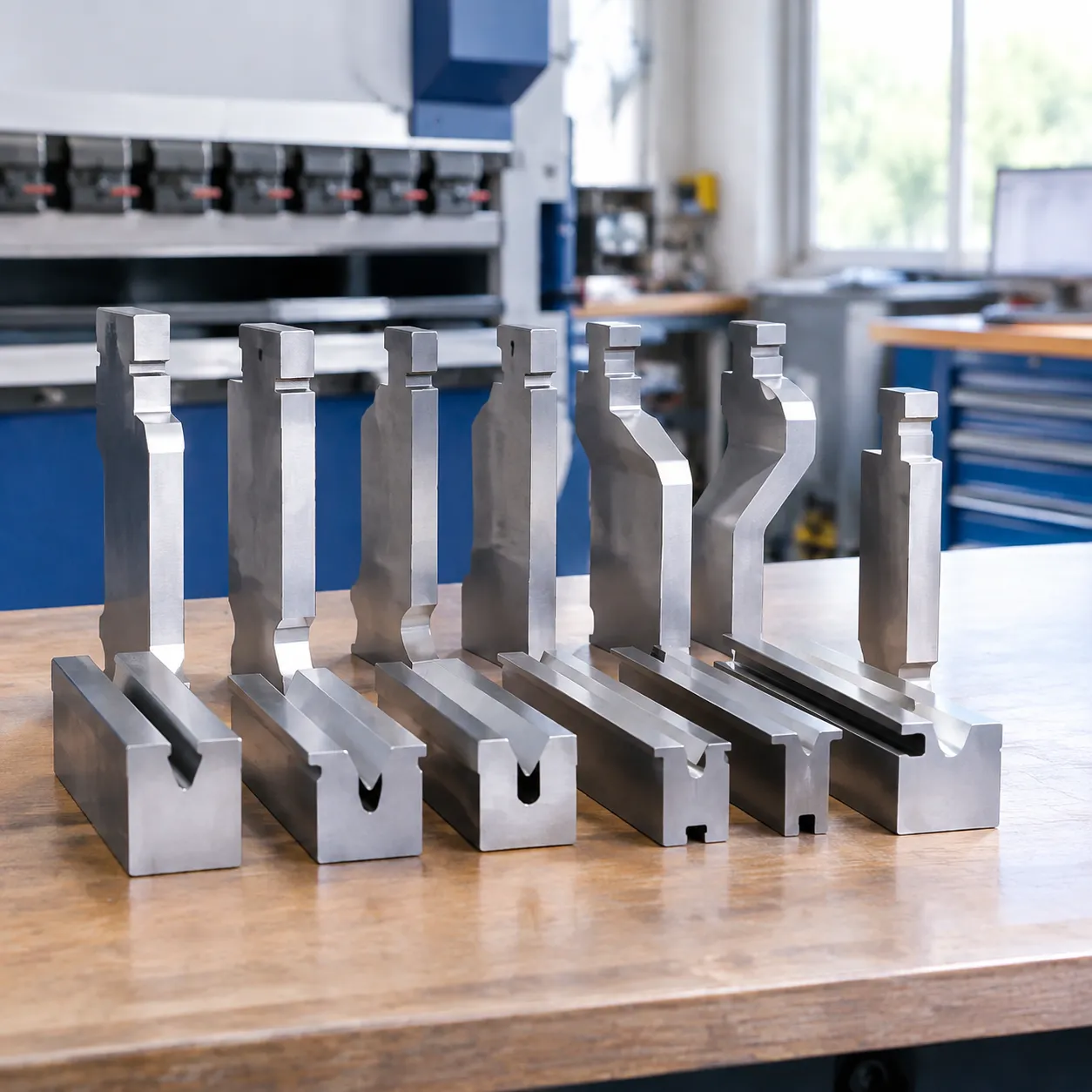
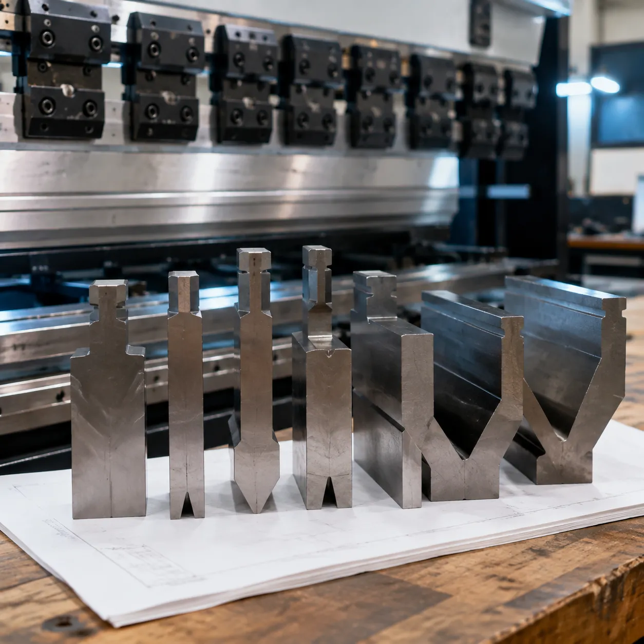
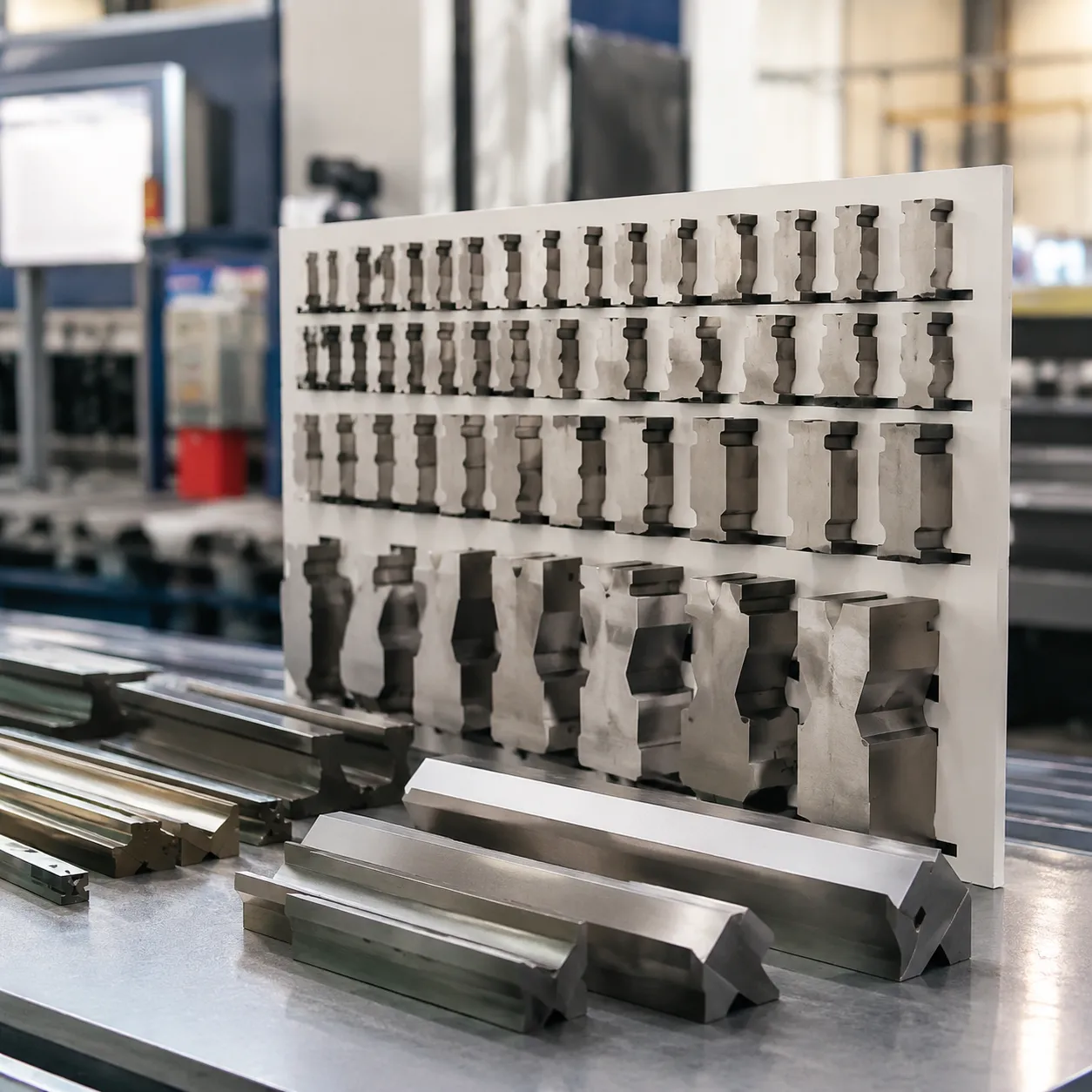
Mastering sheet metal bending starts with understanding lower tooling geometry. Key press brake die dimensions determine your tonnage limits, inside radius accuracy, and part finish quality during air bending operations.
V-Opening Width (V)
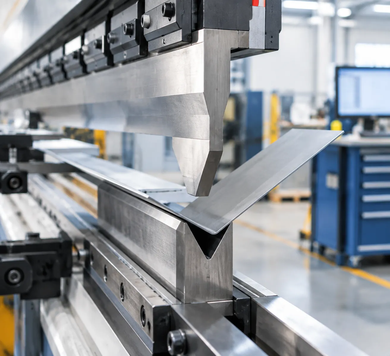
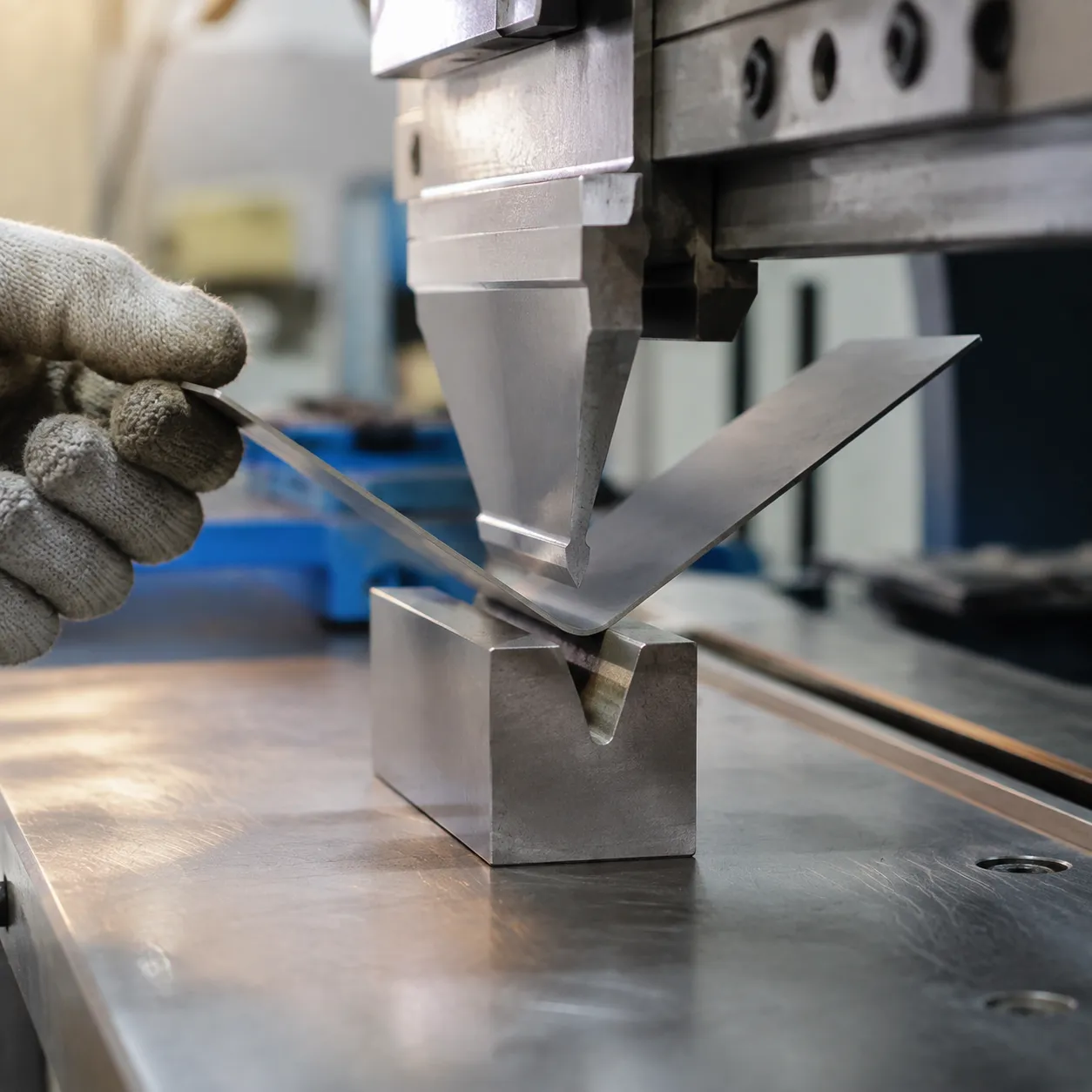
The V-opening width is the primary governing metric in air bending mechanics. It directly controls the force required to form the sheet and dictates the final inside bend radius.
Tonnage Control: Expanding the V-opening lowers the required bending force but increases the resulting inside bend radius.
Selection Metric: Matching your sheet thickness to a standard press brake die size chart prevents tool overloading and ensures consistent angle repeatability.
Die Shoulder Radius (Rs)
The shoulder radius is the entry transition where the sheet slides into the V-groove during the ram stroke.
Friction Reduction: Polished shoulder radii minimize surface friction and material drag.
Part Protection: Correct shoulder sizing eliminates deep bend mark lines on delicate stainless steel and aluminum sheets.
V-Angle and Springback
Lower dies are manufactured with specific V-angles to match target bend profiles and compensate for material springback.
Standard 88° and 90° Dies: Best suited for general right-angle air bending on mild steel.
30° Acute Dies: Essential for high-springback alloys, tight radius forming, and preliminary steps in two-stage hemming setups.
Press Brake Working Height (H) and Base Width (B)
Tooling envelope dimensions guarantee press brake shut height compatibility and bed stability under load.
Standard Press Brake Die Height: Maintains consistent shut height across different die configurations to eliminate complex shimming.
Base Width (B): Delivers a stable footprint across the bed table to prevent die tipping under heavy tonnage.
Sectionalized Tooling Lengths
Modular tool sizing optimizes setup flexibility for complex pan and box forming without requiring custom full-length dies.
Standard Lengths: 835 mm and 415 mm segments for long, continuous bending runs.
Segmented Sets: Multi-piece sets with end horn segments that provide side-wall clearance for four-sided box fabrication.
Rules for Selecting V-Die Openings
The Baseline 8x t Rule
For standard mild steel (~60,000 PSI tensile strength), our default rule of thumb is V = 8 x t. This 8x ratio provides an ideal balance between manageable tonnage requirements, predictable springback, and a natural inside bend radius roughly equal to 16% of the V-opening.
Tight Radii for Thin Gauges (6x t)
When part specs call for tighter inside radii on thin sheet metal, we drop the opening down to V = 6 x t.
- Pros: Produces smaller inside bend radii and shorter minimum flange lengths.
- Cons: Increases required forming tonnage by roughly 30% to 35% and places significantly higher stress on your lower tooling.
High Tensile and Thick Plates (10x to 12x t)
Forming heavy plate or high-yield materials demands wider press brake die sizes to distribute the bending force over a larger contact surface. We step up to 10x t or 12x t V-openings when working with thick plate to prevent surface cracking during stainless steel processing and keep hydraulic forces within safe working limits.
Material Multipliers for Tonnage Calculations
The standard 8x rule assumes mild steel. When switching metals, adjust your baseline force assumptions using these material multipliers before checking your press brake die size chart or running a V-die opening calculation:
- Soft Aluminum (e.g., 5052-H32): 0.5x force — Requires half the tonnage of mild steel with minimal springback.
- Mild Steel (A36 / Cold Rolled): 1.0x force — The benchmark baseline for standard air bending formulas.
- Stainless Steel (304 / 316): 1.5x force — Higher yield strength requires 50% more tonnage; review our press brake die rating guide to prevent tooling deformation.
- High-Strength Alloys (Hardox / High-Yield): 2.0x to 2.5x force — Requires double the force and wide 10x–12x V-openings to protect both machine and tooling.
Press Brake Die Size Chart and Tonnage Guide
We built this reference chart to remove the guesswork when matching sheet metal thickness to proper press brake die dimensions. Utilizing our standard press brake v-die chart and tonnage guide helps prevent equipment damage and ensures clean, precise bends on every cycle.
Press Brake Die Size Chart (Metric & Imperial)
Here is our quick-reference mapping for air bending standard mild steel (60,000 PSI / 420 MPa tensile strength) based on the baseline 8x t rule:
| Material Thickness (t) | Gauge (US) | Recommended V-Opening (V) | Min. Flange Length (b) | Predicted Inside Radius (R) | Est. Tonnage (Tons/Meter) | Est. Tonnage (Tons/Foot) |
|---|---|---|---|---|---|---|
| 0.8 mm | 22 Ga | 6 mm (0.25") | 4.2 mm | 1.0 mm | 8 t/m | 2.5 t/ft |
| 1.0 mm | 20 Ga | 8 mm (0.31") | 5.5 mm | 1.3 mm | 10 t/m | 3.0 t/ft |
| 1.5 mm | 16 Ga | 12 mm (0.47") | 8.5 mm | 2.0 mm | 14 t/m | 4.2 t/ft |
| 2.0 mm | 14 Ga | 16 mm (0.63") | 11.5 mm | 2.7 mm | 18 t/m | 5.5 t/ft |
| 3.0 mm | 11 Ga | 24 mm (0.94") | 17.0 mm | 4.0 mm | 28 t/m | 8.5 t/ft |
| 4.0 mm | 8 Ga | 32 mm (1.25") | 22.5 mm | 5.3 mm | 38 t/m | 11.5 t/ft |
| 6.0 mm | 1/4" | 50 mm (2.00") | 35.0 mm | 8.3 mm | 58 t/m | 17.5 t/ft |
| 8.0 mm | 5/16" | 64 mm (2.50") | 45.0 mm | 10.6 mm | 78 t/m | 23.5 t/ft |
| 10.0 mm | 3/8" | 80 mm (3.15") | 56.0 mm | 13.3 mm | 98 t/m | 29.5 t/ft |
Note: For stainless steel, multiply the estimated tonnage by 1.5. For soft aluminum, multiply by 0.5.
Calculating Air Bending Tonnage
Before running a job, we always run a quick air bending v width calculation to avoid overloading the machine or causing permanent deformation on a female press brake v-die.
For standard mild steel, use this standard empirical formula:
P = (65 x S x t²) / V
- P = Required force in metric tons per meter
- S = Material tensile strength in kg/mm² (Mild steel ≈ 42 kg/mm²)
- t = Sheet metal thickness (mm)
- V = V-opening width (mm)
Rules to Prevent Tooling Deformation & Overload
- Check the stamped limit: Every precision ground die has a maximum tonnage limit stamped directly on its body—never exceed this limit.
- Exercise caution with narrow V-openings: Dropping your V-opening from 8x t to 4x t doubles the required bending force.
- Account for material hardness variations: High-tensile materials require significantly higher force; ignoring material multipliers can lead to sudden tool cracking.
Geometric Checks Before Setup: Radius & Minimum Flange Formulas
Before cycling the press, running two critical geometric calculations prevents scrapped parts, ruined tool edges, and unwanted sheet drop. Matching your sheet metal thickness gauge ratio to exact press brake die dimensions ensures consistent bend angles and accurate flat pattern developments.
Predicting Inside Bend Radius via the 20% Rule
In air bending, the punch radius does not dictate the final inside bend radius ($R_{in}$). Instead, the inside radius forms naturally across the V-die opening as a percentage of its width. We rely on the 20% Rule to predict the natural inside radius based on material tensile strength:
- Stainless Steel (High Resistance): Inside radius = 20% – 22% of V-opening width
- Cold Rolled Steel (Standard): Inside radius = 15% – 17% of V-opening width
- Soft Aluminum (Low Resistance): Inside radius = 10% – 12% of V-opening width
Applying this inside bend radius formula to your air bending V width calculation helps predict bend deduction before hitting the pedal. To match strict print specifications, choose specialized radius punches that complement your selected lower die geometry.
Preventing Sheet Drop: Minimum Flange Length Requirement
If a part flange is too short, the material slips off the die shoulder mid-stroke, dropping into the V-groove and destroying part accuracy.
To maintain continuous support across the die shoulders during stroke depth, calculate the minimum flange length using these ratios:
- Standard 88°–90° Dies: Minimum Flange = 70% of V-opening width (V × 0.7)
- Acute 30° Dies: Minimum Flange = 75% – 80% of V-opening width (V × 0.75)
| V-Opening Width (V) | Minimum Flange Length (Standard 90°) | Typical Sheet Thickness Range |
|---|---|---|
| 8 mm (0.315 in) | 5.6 mm (0.220 in) | 0.8 mm – 1.2 mm |
| 12 mm (0.472 in) | 8.4 mm (0.330 in) | 1.5 mm – 2.0 mm |
| 16 mm (0.630 in) | 11.2 mm (0.440 in) | 2.0 mm – 2.5 mm |
| 25 mm (0.984 in) | 17.5 mm (0.689 in) | 3.0 mm – 4.0 mm |
Cross-checking your part drawings against our standard press brake die size chart prevents sheet drop and eliminates surface marking. For tricky bend sequences or narrow sheet metal bending clearance limits, reach out through our technical support services to verify tooling clearances before production runs.
Die Geometry Categories and Application Profiles
| Die Category | Target Application | Primary Dimension Specs | Major Operational Benefit |
|---|---|---|---|
| Single V-Dies | High-precision air bending & acute angles (30°) | Precise V-angle, ground shoulder radius | Maximum clearance, minimal part marking |
| Multi-V & 4-Way Blocks | Multi-thickness job shop processing | 4 standard V-openings on 1 block | Fast flip setup, zero tool-change downtime |
| Hemming & Flattening | Safety edges & high-rigidity double-thickness hems | Two-stage acute & spring-loaded flat | Combines pre-bend and closing in one station |
| Gooseneck & Clearance | Deep return bends & channel clearance | Relief cutouts, extended working height | Prevents side-wall collisions on return bends |
| Adjustable V-Width | Heavy plate bending & structural steel | Motor-controlled variable V-opening | Eliminates physical tool swapping on thick plate |
Single V-Dies for High-Precision Air Bending
Single V profiles are the foundation of precision sheet metal forming. By combining narrow V-openings with tight shoulder radii, our single V-dies handle acute angle forming down to 30° without binding the stock. They offer maximum front-to-back clearance for tight offset bends.
Multi-V and 4-Way Block Dies
Swapping individual lower dies for every gauge change slows down production. A rotating multi-V die block consolidates four distinct V-openings into a single tool body. Operators simply rotate the block on the press brake bed to process multiple material thicknesses without changing out the bed setup.
Hemming and Flattening Combinations
Forming smooth safety edges requires a fast two-step sequence:
Stage 1 (Pre-bend): An acute upper punch forces the sheet into a 30° acute V-die angle.
Stage 2 (Flattening): The lower spring-loaded table depresses under tonnage, crushing the acute bend flat into a finished hem.
Gooseneck and Clearance Lower Tooling
Complex deep-box profiles and narrow return flanges often contact standard square die shoulders. Clearance dies feature relief cutouts and stepped shoulders that accommodate return legs, ensuring the sheet clears the tool body during the full press stroke.
Adjustable V-Width Lower Tooling
For heavy plate fabricators using a large press brake die size chart, manually swapping 100 mm to 200 mm lower dies requires cranes and overhead rigging. CNC-driven adjustable lower dies use motorized lead screws to widen or narrow the lower V-gap on the fly, matching required plate thicknesses automatically.
Press Brake Die Dimensions Across Mounting Styles
Matching press brake die dimensions to your machine's clamping system is critical for tool longevity, operator safety, and bend accuracy. We precision-engineer lower tooling across all three dominant global mounting standards to ensure exact alignment and zero bed slop.
European Precision Style
European tooling uses a standardized 13 mm tang width with precise shoulder locating grooves.
Tang Geometry: 13 mm x 20 mm standard tang with precision-ground centering surfaces.
Groove Depth: Optimized profile seating depths eliminate side deflection during high-tonnage air bends.
Compatibility: Native fit for Amada, Bystronic tooling setups, LVD, and European-style clamping receivers.
American Traditional / Precision Style
American style tooling relies on a traditional centered tang design locked in via set screws or mechanical clamps.
Tang Geometry: 0.500 in (12.7 mm) wide by 0.625 in (15.87 mm) high safety tang.
Clamping Mechanics: Manual set-screw engagement into the bed or die holder slot.
Compatibility: Standard fit for Cincinnati, Pacific, and Accurpress machinery; easily outfitted using our specialized American style tooling lineup.
New Standard / WILA Style
New Standard tooling features automated hydraulic or mechanical self-seating mechanisms for rapid tool changeovers.
Tang Geometry: Precision-milled 20 mm tangs with automated Safety Click buttons or locking pins.
Seating Mechanism: Hydraulic pressure pulls the die directly into the bed, aligning to ±0.01 mm without manual shimming.
Compatibility: Direct match for WILA, Trumpf, and modern automated CNC press brakes.
European Style vs American Precision Tooling Dimensions
| Mounting Style | Tang Width | Tang Height / Groove Spec | Primary Clamping Method | Typical Machine Compatibility |
|---|---|---|---|---|
| European Precision | 13 mm (0.512 in) | 20 mm (0.787 in) | Quick-clamp / Mechanical side locks | Amada, Bystronic, LVD, Trumpf |
| American Traditional | 12.7 mm (0.500 in) | 15.87 mm (0.625 in) | Set screws / Mechanical die holder | Cincinnati, Pacific, Accurpress |
| WILA / New Standard | 20 mm (0.787 in) | Self-seating groove + Safety Pin | Hydraulic / Pneumatic automatic clamping | WILA, Trumpf, Premium CNC Brakes |
CAMT Precision Standards for Press Brake Die Dimensions
Maintaining exact profile tolerances on your shop floor starts with how lower tooling is engineered. We manufacture our tooling to strict quality benchmarks so that every spec matching your press brake die size chart delivers predictable, high-precision bends without constant machine recalibration.
Micron-Level Dimensional Accuracy
- Precision Ground Tolerances: We grind every critical working surface to profile tolerances of ±0.01 mm.
- Seamless Repeatability: Uniform press brake die dimensions across all tool sections eliminate height variations, ensuring seamless sectionalized staging and fast setup times.
Mirror Surface Finish (Ra < 0.8 µm)
- Friction Reduction: Polished V-die shoulder radii with an Ra < 0.8 µm finish drastically reduce sheet metal drag during the bend cycle.
- Galling Prevention: Smooth contact surfaces prevent material pickup and help eliminate work-marking on sensitive stainless steel or aluminum sheets.
Metallurgy & Hardening Standards
- High-Grade 42CrMo4 Tool Steel: We build our tooling using high-grade 42CrMo4 alloy tool steel to handle intense tonnage without deformation. For deeper insight into selecting tool steel alloys, explore our comprehensive press brake tooling material guide.
- Deep Induction Hardening: High-wear working zones feature targeted induction hardening to 55–60 HRC, yielding deep induction hardened dies that offer up to 3x longer operational life under heavy-duty press brake cycles.
Quality Assurance Matrix
- 100% Optical CMM Inspection: Every profile undergoes full 3D CMM optical scanning to verify exact radii and V-opening geometry.
- Material & Hardness Verification: Spectro testing verifies alloy composition, while multi-point Rockwell testing ensures consistent core-to-surface strength across our inventory of metal forming press brake dies.
Custom Press Brake Die Ordering from CAD Files
When off-the-shelf options in a standard press brake die size chart don't match your part geometry, we work directly with your engineering files to build tailored solutions. Send us your 2D files (DXF or DWG) alongside 3D models (STEP or IGES). This helps us analyze every key detail—from critical flange clearances and material springback to exact press brake die dimensions—before cutting tool steel. Through complete OEM/ODM collaboration, our team turns complex part profiles into rugged, drop-in lower tooling.
3D Bending and Collision Simulation
To prevent costly shop-floor surprises, we run digital stroke simulations on every custom build before manufacturing begins:
- Collision Detection: We simulate the entire press brake stroke to catch potential interference between part legs, upper punches, and lower die shoulders.
- Clearance Verification: We verify deep channel bends, return legs, and tight offset geometries before high-precision steel grinding starts.
- Tonnage Safety Check: We cross-reference your material thickness and bend radius against die strength to eliminate the risk of premature tool deformation.
CAMT 5-Step Custom Workflow
We streamline custom manufacturing into a transparent, high-precision workflow. If you need dedicated shapes or engineering support, learn more about our custom press brake tooling capabilities or take advantage of our drawing optimization team.
- CAD File Submission: Submit your 2D (DXF/DWG) drawings and 3D (STEP) CAD models for technical review.
- Tonnage Feasibility Review: We calculate maximum load requirements and verify machine shut-height compatibility.
- Drawing Optimization: Our engineers refine die geometry, V-angles, and shoulder radii to extend tool life and prevent part marking.
- CMM Sample Verification: We inspect test-cut tooling using 100% CMM optical measurement to ensure strict ±0.01 mm precision.
- Rapid Batch Production: Once approved, we move directly into deep induction hardening and final precision grinding for batch delivery.
Press Brake Die Size & Selection FAQs
What is the 8x rule for selecting press brake V-die openings?
The 8x rule is our baseline standard for air bending cold-rolled mild steel. It dictates that your lower V-die opening width (V) should equal eight times your material thickness (t):
- Formula: V = 8 × t
- Why it matters: It balances machine tonnage demands with a clean, natural inside bend radius (roughly 16% of V).
- When to adjust: Drop to 6 × t for thin sheet parts requiring tight radii. Scale up to 10x–12x t on heavy plate or stainless steel to cut down required bending force and avoid cracking.
How do I calculate the minimum flange length for a given press brake die size?
To keep your sheet supported across the die shoulders during the stroke without dropping into the V-groove, you must maintain a safe minimum flange height.
- Rule of Thumb: Minimum Flange = 0.7 × V
- Example: If your press brake die dimensions call for a 16 mm V-opening, your minimum flat flange length must be at least 11.2 mm (16 × 0.7). Any flange shorter than this will slip into the die gap before completing the bend.
What causes bend mark lines on sheet metal and how do die dimensions eliminate them?
Bend marks occur when sheet metal drags under heavy tonnage across sharp die shoulder radii. You can eliminate or drastically reduce these lines by tuning your die setup:
- Larger Shoulder Radii: Smooth, generously radiused die shoulders distribute friction across a wider area.
- Wider V-Openings: Increasing V-width lowers the required tonnage, reducing contact friction.
- Multi-V Tooling: Using a 4-way press brake die with polished, induction-hardened shoulders prevents metal pickup and galling.
- Protective Barriers: Placing protective urethane tape over the V-opening shoulders buffers polished aluminum or stainless parts.
How do European, American, and WILA style press brake die dimensions differ?
Tooling styles vary mainly in tang geometry, mounting mechanisms, and center-line alignment standards:
- European Precision Style: Uses a standard 13 mm tang width with precise center alignment. Common on Amada, Bystronic, and LVD machines.
- American Traditional Style: Features a 0.5 in (12.7 mm) wide tang secured manually with set screws in traditional die holders.
- WILA / New Standard Style: Engineered for hydraulic power clamping with self-seating pin grooves, automatic alignment, and micron-level precision tolerances (±0.01 mm).