
Are you struggling with inaccurate bends, cracked parts, or wasted shop time?
The truth is, flawless sheet metal bending comes down to one critical factor: proper press brake die selection.
Choose the wrong tooling, and you risk damaging your machine and ruining expensive materials. Choose the right one, and you’ll achieve pinpoint precision, faster setup times, and cleaner bends on every single run.
In this practical guide, you'll learn the exact rules, formulas, and tooling types you need to make the right choice with complete confidence.
Let's dive right in.
Fundamental Bending Methods & Their Impact on Die Selection
Choosing the right press brake die begins with selecting your forming method. The mechanical interaction between the punch, sheet metal, and V-die determines your machine load, angular accuracy, and tooling lifespan.
Every forming style demands a distinct approach to die angles, opening widths, and tip profiles.
| Bending Method | Typical Tonnage Requirement | Angle Dependency | Tooling Profile Match | Common Application |
|---|---|---|---|---|
| Air Bending | Baseline (1x) | Punch penetration depth | Acute or standard (e.g., 85°, 88°, 30°) | High-mix production, varied angles |
| Bottom Bending | 3x to 5x Baseline | Tool geometry & depth | Exact match to part (e.g., 90° tool for 90°) | High repeatability on thinner gauges |
| Coining | 8x to 10x Baseline | Extreme direct pressure | Exact match with sharp punch radius | Ultra-precise small parts (legacy setups) |
Air Bending Mechanics and Tonnage Benefits
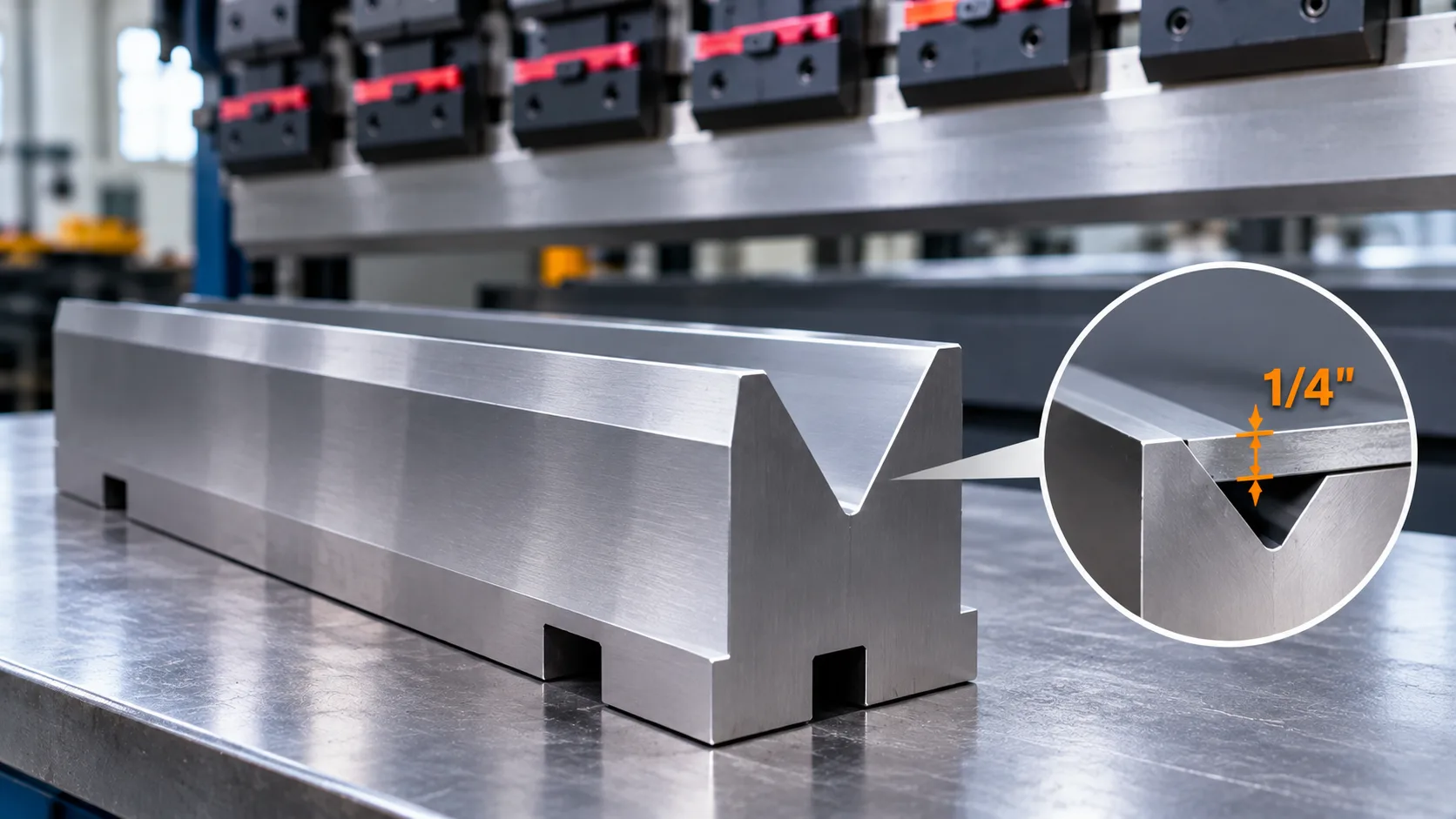
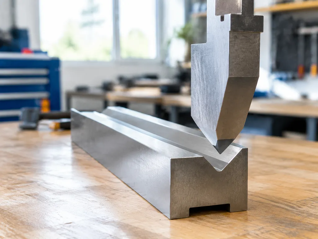
Air bending is the industry standard for modern CNC precision fabrication. The sheet contacts only three points: the punch tip and the two shoulder radii of the lower V-die. The final bend angle is determined solely by how deep the punch descends into the die opening, not by matching the tool's cut angle.
- Low Tonnage Demand: Requires the lowest tonnage of all three methods, reducing wear on machine hydraulics and side frames.
- Versatility: A single 85° or 88° V-die can produce a wide range of angles from 180° down to 90° simply by altering the punch stroke depth.
- Overbending for Springback: We use acute dies (such as 85° or 75°) to deliberately overbend the sheet metal, allowing it to spring back to a precise 90°.
Bottom Bending Tooling and Tonnage Requirements
In bottom bending (bottoming), the punch presses the material completely against the angled surfaces of the V-die cavity without plasticizing the core structure of the metal.
- Direct Tool Match: Die angles must directly reflect the target bend angle (usually 90° tools for a finished 90° bend), with minor angular relief (such as 88°) to account for residual elasticity.
- Tonnage Surge: Expect machine loads 3 to 5 times higher than air bending.
- Tool Rigidity: Tooling must feature higher centerline load limits per meter to prevent structural cracking along the bottom of the V-groove.
Coining Limitations in Modern Precision Fabrication
Coining stamps the punch profile directly into the neutral axis of the sheet, thinning the metal at the bend radius and completely eliminating springback.
- Severe Equipment Overload: Tonnage requirements spike to 8 to 10 times that of air bending, often exceeding rated tooling limits and risking tool fracture.
- Premature Tool Wear: Punch tips flatten and lower V-die shoulders degrade rapidly under high tonnage concentrations.
- Obsolescence: With modern high-precision CNC crowning systems and precision-ground air-bend tooling, coining is rarely necessary or recommended in contemporary sheet metal operations.
Step-by-Step Lower V-Die Selection Framework
Picking the right lower die governs your bend accuracy, tonnage demand, and part quality. Follow this straightforward shop-floor framework to dial in your lower V-die selection quickly and avoid scrap.
Applying the 8x Material Thickness Rule
For standard air bending of mild steel up to 0.250 inches (6.35 mm), we stick to the industry standard 8x rule:
- Formula: V = 8 * t (where V is the V-die opening width and t is the sheet metal thickness).
When working with materials outside standard gauges, adjust your multiplier to protect tooling and maintain clean parts:
Thin sheet (< 1 mm / 20 gauge or thinner): Use 6x to 8x t to prevent sheet wrinkling.
Standard gauge (1 mm to 6 mm): Use 8x t for the best balance of tonnage and radius stability.
Thick plate (> 6 mm to 12 mm): Step up to 10x t to lower bending forces and prevent surface cracking.
Heavy plate (> 12 mm): Use 10x to 12x t or larger. For heavy-duty forming setups, review our guide on the air bending bottom die opening for 2-inch thick materials to keep machine loads well within safety limits.
Calculating Natural Inside Bend Radius from V-Opening Width
In air bending, the punch nose doesn't establish the inside radius unless bottoming. The sheet naturally creates a radius based directly on your die opening width:
- Inside Bend Radius (Ri): Ri ≈ 5/32 * V (or approximately 0.156 * V to 0.16 * V for mild steel).
- Stainless Steel: Expect a slightly larger radius (0.18 * V to 0.20 * V) due to higher tensile strength and resistance to flow.
- Soft Aluminum: Yields a tighter radius (0.12 * V to 0.14 * V).
Always base your bend deduction and flat pattern calculations on this natural inside radius rather than punch tip radius alone.
Determining Minimum Flange Length Limits
A flange must span across both shoulders of the V-die without falling through during the stroke. To ensure stability during forming:
- Standard 90-Degree V-Die Minimum Flange (b_min): b_min ≈ 0.7 * V (measured from the outside edge to the bend apex).
- Acute 30-Degree to 60-Degree Dies: b_min ≈ 0.8 * V due to the deeper drop required before the sheet touches the die shoulders.
If your part design calls for a flange shorter than 0.7 * V, using a standard V-die will pull the part down into the cavity, skewing your bend line and distorting the edge.
Selecting Narrow and Rotary Wing Dies for Short Flanges
When part geometry forces you into tight clearances or ultra-short flanges, switch out standard fixed-shoulder dies:
- Narrow V-Dies: Feature smaller shoulder radii and slim profiles to clear tight return bends, but they elevate localized contact stress.
- Rotary Wing Tooling: Uses rotating cylindrical cams that support the sheet continuously from the start of the stroke. Equipping press brake dies with rollers for mark-free bending lets you bend flanges as short as 0.35 * V while completely eliminating die drag lines on pre-painted or polished sheets.
- Adjustable V-Dies: Ideal for high-mix job shops processing heavy plates, allowing operators to change openings mechanically in minutes without swapping heavy tooling blocks.
Punch Profile and Geometry Selection
| Punch Type | Best Application | Primary Geometry Advantage |
|---|---|---|
| Straight Punch | Simple open bends, 90° angles | Maximum vertical load capacity |
| Gooseneck Punch | U-channels, deep return flanges | Large relief cutout prevents clashes |
| Acute Punch | High springback, pre-hems (30°) | Deep penetration for overbending |
| Sash Punch | Narrow channels, deep boxes | Slim profile clears tight interiors |
Matching Punch Tip Radius to Avoid Material Cracking
Setting an overly sharp punch tip radius (Rₚ) concentrates excessive tonnage along the bend line, turning the bend into a crease that fractures high-tensile sheet metal.
The Cracking Threshold: For mild steel and aluminum, keep the punch tip radius at or slightly below the natural inside bend radius (Rᵢ).
Grain Direction Awareness: Bending parallel to the sheet grain increases cracking risks; increasing the tip radius mitigates this failure mode.
Tonnage Limits: Understanding proper press brake punch radius selection prevents running a sharp tool into high tonnage zones, which can yield or chip the punch nose.
Standard Straight Punch for Open Profiles
For flat plates, single bends, and wide-open profiles, standard straight punches deliver maximum rigidity. Because they lack deep cutouts, they handle the highest tonnage ratings per meter. We default to straight punches whenever flange clearance is not an issue.
Gooseneck Punch Clearance for Deep Return Flanges
When forming channels or secondary return bends, a standard punch body will collide with previously bent flanges.
- Gooseneck punches feature a deep recessed throat that accommodates inward-facing flanges.
- Keep in mind that the recessed geometry reduces maximum allowable tonnage by 30% to 50% compared to straight tools. Always verify tonnage limits before bottoming with a gooseneck.
Acute Angle Punch for High-Springback Alloys
Air bending stainless steel or high-yield materials requires significant overbending to compensate for springback.
- We use acute punches with tip angles of 30 °, 45 °, or 60 ° to push the sheet past its yield point.
- Pair an acute punch with matching tooling based on our press brake die angles guide to achieve exact final dimensions without bottoming out.
Sash Punch for Narrow Window and Deep Box Bending
Forming narrow cross-sections, deep four-sided boxes, or window profiles creates tight clearance constraints where standard bodies bind. Sash punches feature an extended, narrow profile with minimal shoulder width, giving the required clearance inside tight, boxed enclosures while maintaining sufficient vertical centerline strength.
Material Specifics & Tonnage Verification in Press Brake Die Selection
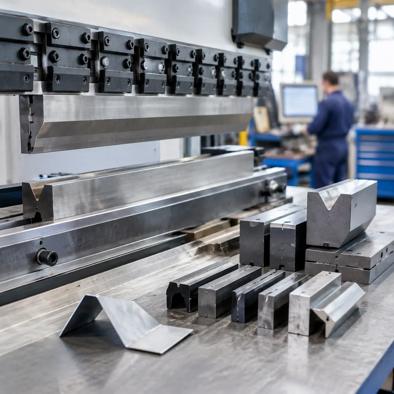
Material Multipliers for Mild Steel, Stainless, and Aluminum
Standard air bending tonnage charts base their calculations on structural mild steel with an average tensile strength of 450 N/mm² (around 60,000 PSI). When forming alloys with different mechanical properties, we apply a material factor (MF) to the base air bending tonnage calculation:
| Material Type | Tensile Strength (Rₘ) | Material Factor (MF) | Recommended V-Opening |
|---|---|---|---|
| Soft Aluminum (3003/5052) | 200–250 N/mm² | 0.5–0.6 | 6 × t to 8 × t |
| Mild Steel (A36/1018) | 400–450 N/mm² | 1.0 (Baseline) | 8 × t |
| Stainless Steel (304/316) | 650–750 N/mm² | 1.4–1.6 | 10 × t to 12 × t |
| High-Strength Steel (Hardox/Domex) | 1000+ N/mm² | 2.0–2.5 | 12 × t to 14 × t |
t = Material thickness
Always consult a verified press brake V-die chart and tonnage guide to confirm your theoretical tonnage before running unfamiliar alloys. High-yield materials demand larger V-openings to keep tonnage within acceptable machine and tool limits while minimizing extreme springback.
Calculating Press Brake Tooling Load Limit per Meter
Every punch and die carries a maximum allowable load limit expressed in metric tons per meter (t/m) or tons per foot. Exceeding this value permanently deforms the tool body or splits the V-shoulder.
To determine the maximum safe tonnage for a specific bend length:
Max Safe Tonnage = Tool Rating (t/m) × Part Length (m)
For short parts, the allowable load drops drastically:
Full-length bending: Load distributes evenly across the bed.
Short workpieces (< 100 mm): The machine's concentrated hydraulic force can exceed the local yield point of the tool steel, even if the total press tonnage display shows a "safe" low value.
Evaluating the structural properties outlined in a press brake tooling material guide ensures your chosen tool steel (such as 42CrMo or Cr12MoV) provides the core toughness needed to resist high-tonnage cycling.
Preventing Localized Tool Overload and Punch Fracture
Tool damage rarely happens uniformly; it occurs when high tonnage concentrates on a narrow contact area. We use three shop-tested rules to eliminate tool blowout:
Avoid Sharp Punch Radii on Thick Plate: Forcing a small punch tip radius (r ≤ 0.8 mm) into thick plate causes immediate point-loading at the punch apex, creating micro-fractures along the tip.
Enlarge V-Openings for High Tensile Stock: When running 304 stainless or armor plate, expanding the die width from 8 × t to 10 × t or 12 × t reduces required forming tonnage by roughly 20% to 30%, keeping point pressures well below the tool's plastic deformation threshold.
Never Center Short, Heavy Bends on Weak Tooling: When bending narrow, heavy-gauge tabs, use specialized heavy-duty punches with reinforced shoulders rather than narrow sash or gooseneck profiles that lack lateral backup mass.
Special Bending Applications & Advanced Press Brake Die Selection
Two-Stage Hemming and Dutch Bend Setups
Creating safe edges, structural stiffeners, or Dutch bends requires a two-step process: pre-bending to an acute angle (typically 30°) and flattening the sheet.
- Combination Spring-Loaded Hemming Dies: We use two-in-one combination hemming dies to perform both the acute pre-bend and the final flattening stroke on a single machine station without swapping tools.
- Standard 30° Acute Die + Flattening Block: Best for low-volume runs. The part is air-bent in an acute V-die first, then shifted to a flat anvil punch/die block to close the hem.
- Tonnage Note: Flattening requires roughly 3 to 4 times the tonnage of standard air bending. Always verify your press brake frame rating before running full-length closed hems.
Mark-Free Urethane Tooling and Rotary Dies for Cosmetic Sheets
When forming pre-painted panels, mirror-finish stainless, or soft aluminum, standard steel shoulder radius contact causes visible galling and drag lines.
- Polyurethane Inserts & Film: We deploy custom polyurethane radius tooling pads and urethane V-dies to wrap the sheet during penetration, fully isolating the material from hardened steel contact to eliminate secondary polishing.
- Rotary Wing Dies: Replace traditional static shoulders with rotating hardened cylindrical rolls. The wings pivot with the workpiece during the stroke, eliminating friction scratches and reducing the required minimum flange length (bₘᵢₙ) down to roughly 1.5 × t.
Quick-Change Segmented Tooling vs Multi-V Blocks
| Tooling Type | Best Application | Setup Time | Alignment Precision |
|---|---|---|---|
| Precision-Ground Segmented Tooling | Complex box bending, deep return flanges, frequent job changeovers | Fast (Push-button / quick-clamping) | ± 0.01 mm (Interchangeable) |
| Solid Multi-V Die Blocks | Heavy-gauge plate bending (t \ge 6 mm), single-piece long runs | Slow (Requires crane/forklift rotation) | Standard (± 0.05 mm) |
We specify segmented tooling when fabricating 4-sided boxes and deep return channels that require cutouts and punch horn clearance. For structural plate bending where high tonnage overrides profile complexity, multi-V blocks remain the most economical, high-capacity lower die choice.
Critical Press Brake Die Selection Mistakes to Avoid
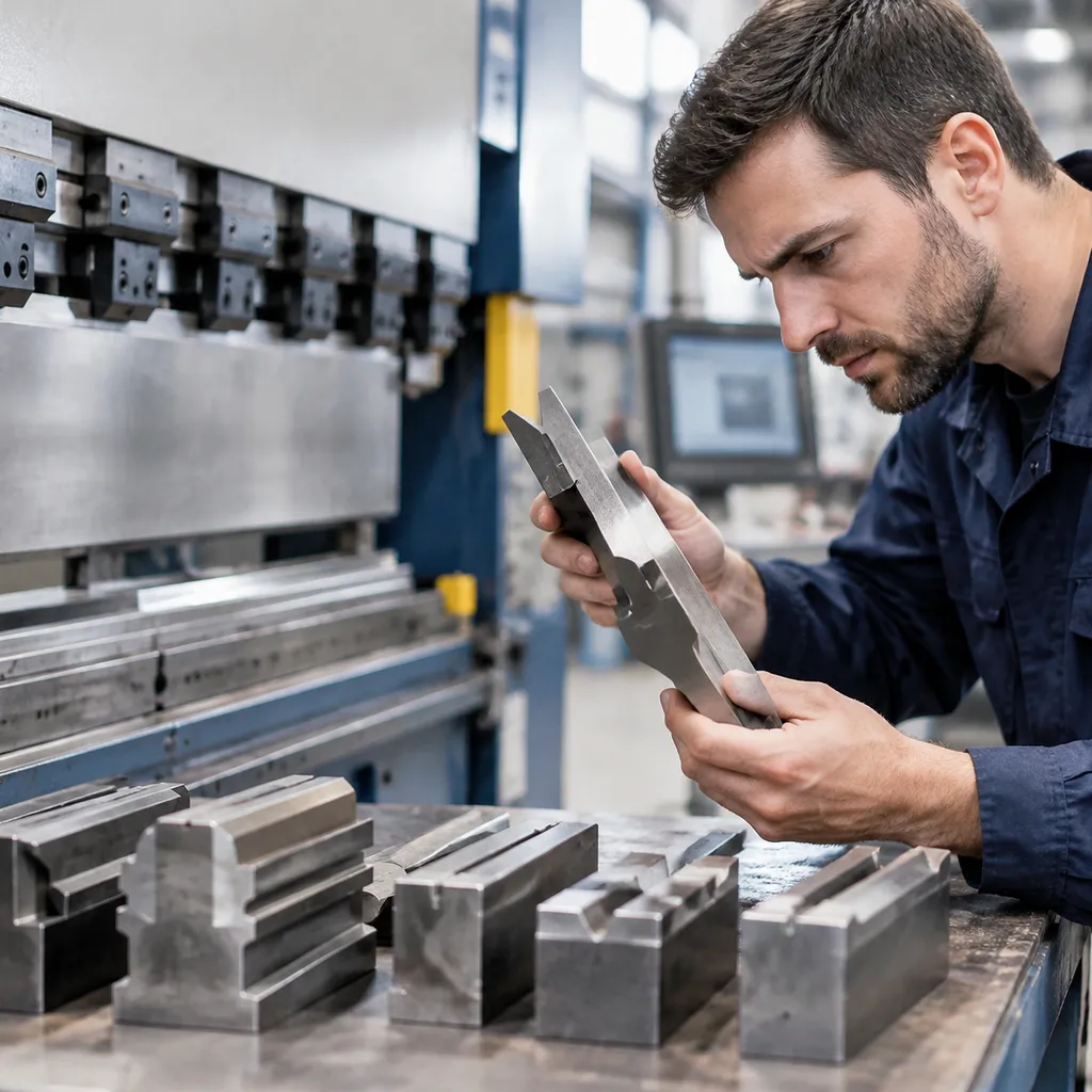
A single bad tooling choice can ruin raw stock, crack expensive punches, or wreck a press brake ram. When setting up a job, we regularly catch operators making five critical mistakes during press brake die selection:
1. Undersizing the V-Die Opening for Tight Radii
Choking down the V-opening to force a smaller inside radius spikes required tonnage exponentially. Violating the standard 8x material thickness rule on thick sheets risks:
Overtonnage failures: Punch tips fracture and die shoulders deform under excessive pressure.
Severe part marking: The sheet gets deep friction gouges along the die entry radius.
Orange-peel cracking: Stretching the outer grain of the metal past its tensile limit causes structural tears.
2. Ignoring Material Springback During Air Bending
Air bending always requires overbending past the target angle. Selecting an 88° or 90° die for high-strength steel or structural aluminum fails to give the punch enough angular travel. Always pick an acute angle die (30° to 75°) when forming materials with high yield strength to compensate for substantial springback.
3. Exceeding Tooling Center-Line Tonnage Ratings
Every punch and die has a maximum tooling load limit per meter. Running a short, high-tonnage bend across a narrow section concentrates the force entirely onto a small contact area. Always cross-reference your calculated tonnage against the tool’s rated capacity to avoid split dies and dangerous shrapnel on the shop floor.
Critical Formula: Total Load = Required Tonnage per Foot x Bend Length (ft)
Rule: Never apply concentrated loads on standard segmented tooling without checking point-load limits.
4. Hole Deformation Near Die Shoulders
Placing cutouts or holes too close to the bend line pulls and distorts the geometry as the sheet draws over the die shoulder. If the distance from the hole edge to the bend line is less than half the V-die opening width plus material thickness, the hole drops into the die cavity during forming. To solve this, switch to a narrower V-opening or use rotary wing dies.
5. Clamping Standard Mismatches Across Tooling Systems
Mixing European, Wila/Trumpf, and American standard tooling without proper adapters creates centerline misalignment:
Off-center loading: Pushes side-thrust into the press brake guide rails and hydraulic cylinders.
Angular variation: Minor clamping height discrepancies create inconsistent bend angles across the entire bed length.
Reviewing our guide on standard press brake die types ensures your upper punches, lower dies, and clamping holders match precisely before running high-tolerance jobs.
Frequently Asked Questions About Press Brake Die Selection
How do I choose the right V-die opening for stainless steel?
For stainless steel grades like 304 and 316, increase the standard 8x multiplier to 10x to 12x material thickness (t). Because austenitic stainless steel exhibits higher tensile strength and rapid work-hardening, tighter openings drastically spike tonnage demands and cause heavy tool marking. Pairing the workpiece with a dedicated precision press brake V-die for accurate bending ensures the machine absorbs the 50% to 60% tonnage increase over mild steel without exceeding rated tool limits.
| Material Type | Recommended V-Die Opening | Springback Allowance |
|---|---|---|
| Mild Steel (A36 / CR) | 8 × t | 1.0° to 2.0° |
| Stainless Steel (304/316) | 10 × t to 12 × t | 3.0° to 5.0° |
| Aluminum (5052-H32) | 6 × t to 8 × t | 1.5° to 2.5° |
t = Material thickness
What happens if the punch radius is smaller than the natural inside bend radius?
In air bending, the inside bend radius (Rᵢ) is determined by the V-die opening width (V), typically settling at roughly 15% to 17% of V for mild steel. If the punch tip radius is smaller than this natural radius:
Creasing and scoring: The punch tip penetrates the sheet like a wedge rather than wrapping the material smoothly.
Micro-fracturing: Severe stress concentration along the bend line creates micro-cracks on high-strength alloys.
Inconsistent angles: Variations in material grain direction cause unpredictable angle drift.
Always match the punch tip radius as close to the natural inside radius as possible to prevent deep grooving and premature tool wear.
How do I prevent sheet deformation near pre-punched holes?
Deformation occurs when a cutout or hole falls within the die shoulder contact zone, causing the unsupported edge to stretch during material draw.
To eliminate hole distortion:
Apply the distance rule: Keep hole edges at a minimum distance of 2.5 × t + R_i from the bend line.
Select a narrower V-die: Reducing the V-opening brings the die shoulders closer to the bend line, keeping the hole entirely on the flat plane.
Use specialty tooling: When flange limits prevent standard forming, consult our press brake die clearance guide for better bending or switch to rotary wing dies that support the sheet throughout the entire stroke.
Can I use the same V-die for different bend angles in air bending?
Yes. During air bending, the sheet metal only touches three points: the punch tip and the two die shoulders. The sheet never bottoms out against the die walls.
A single acute V-die (such as a 30° or 60° opening) can form any angle from flat to its minimum profile angle simply by adjusting the CNC ram stroke depth. However, ensure the die shoulder radius is large enough to prevent galling when driving deeper into acute channels.