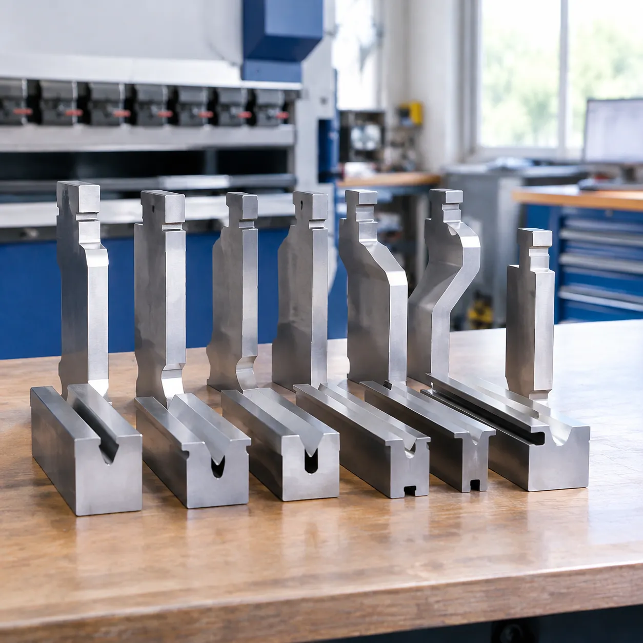
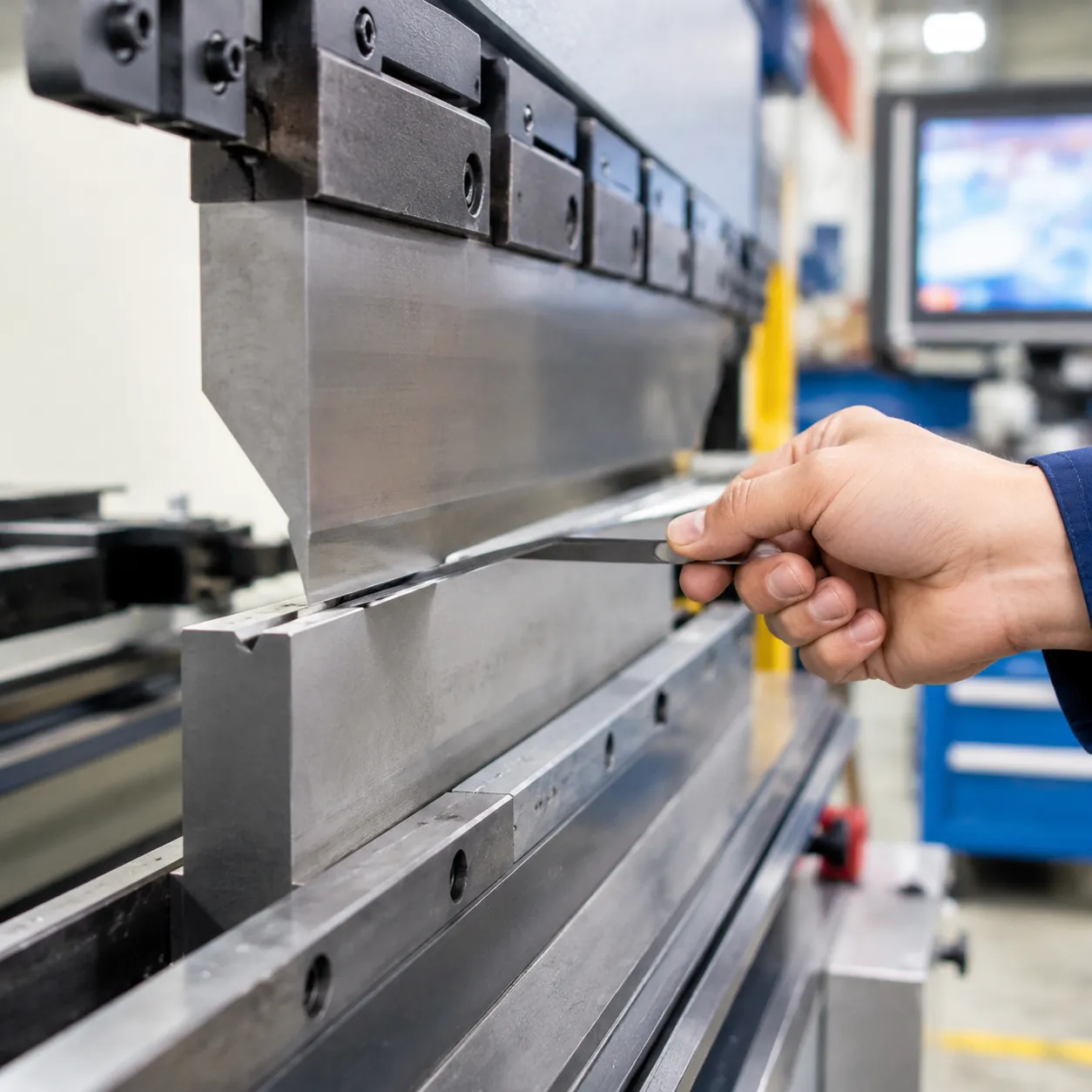
Understanding Press Brake Die Clearance and Core Bending Mechanics
Punch-to-Die Clearance vs. V-Die Opening Width
Many operators confuse overall V-die opening width (V) with punch-to-die clearance. While related, they serve distinct roles on the shop floor:
- V-Die Opening Width (V): The distance between the top contact shoulders of the bottom die. This dimension directly governs your forming tonnage, natural inside bend radius, and minimum achievable flange length.
- Punch-to-Die Clearance: The effective working space between the punch tip face and the die sidewalls during penetration. It determines whether your workpiece bends freely in an air bend or undergoes compressive stress against the die walls.
| Parameter | Shop Floor Definition | Direct Impact on Bending |
|---|---|---|
| V-Die Opening (V) | Distance across top die shoulders | Forms the inside bend radius; sets tonnage demand |
| Punch Nose Radius (Rₚ) | Profile radius on the top tool tip | Sets the minimum inner radius limit; prevents material piercing |
| Material Thickness (T) | Nominal gauge of the sheet metal | Base factor used to calculate proper tooling clearance |
| Working Clearance | Free space between punch, sheet, and die | Controls sheet friction, side galling, and cosmetic marring |
Sheet Thickness, Punch Nose Radius, and V-Opening Dynamics
When we set up a bend, these three variables must work in sync:
- Sheet Thickness (T): Dictates the baseline opening width. Standard air bending relies on scaling the die opening proportionally to material thickness to maintain controllable bending force.
- Punch Nose Radius (Rₚ): Must match the naturally forming inside radius of the sheet. If your punch tip is too sharp relative to the material thickness, it cuts into the inner bend line instead of forming a clean, structural curve.
- V-Opening Width (V): Balances the load. A wider V-opening lowers tonnage and increases the resulting inner bend radius, while a narrower opening tightens the radius at the cost of higher machine tonnage.
Why Clearance Matters: Precision, Finish, and Safety
- Angular Accuracy: Correct clearance stabilizes the neutral axis of the metal, delivering repeatable angles across the full bed length and keeping springback predictable.
- Cosmetic Surface Quality: Proper die shoulder clearance stops excessive drag, eliminating galling, die marks, and scratch defects on decorative or sensitive sheets.
- Tooling and Machine Safety: Undersized die clearance creates steep tonnage spikes that can fracture punch tips, deform die shoulders, and overload your press brake hydraulic system.
Die Clearance Rules Across Different Bending Methods
Air Bending Clearance Mechanics and the 16% Rule
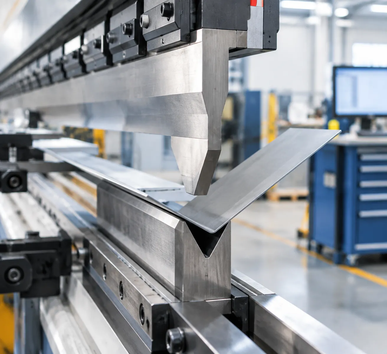
In our daily forming operations, air bending is the go-to standard. The material contacts only three points: the punch nose and the two upper die shoulders. Because the punch never bottoms out, you maintain wide press brake die clearance at the root of the die.
- Clearance Dynamics: The V-die opening is typically sized at 6x to 12x the sheet thickness.
- The 16% Inside Radius Rule: In air bending mild steel, the inside bend radius forms naturally at roughly 16% of the V-die opening width (for example, a 16 mm V-die creates an approximate 2.5 mm inside radius).
- Process Flexibility: A single die set can produce varying angles simply by controlling stroke depth.
When dialing in your air bending tooling setups, reference a reliable press brake V-die chart and tonnage guide to confirm your opening width matches your target inside radius without exceeding machine limits.
Bottom Bending Clearance Requirements
Bottom bending (bottoming) significantly tightens the tooling clearance. The punch presses the material fully against the angled walls of the V-die, though not fully embedding into the metal's structure.
- Clearance Requirements: The die opening is generally tighter, typically locked at 6x sheet thickness.
- Die Wall Contact: As the sheet wraps tightly against the die shoulders and flanks, contact friction increases dramatically.
- Tonnage Impact: Bottoming reduces springback and creates sharper corners, but it requires roughly 3x to 5x the tonnage of standard air bending.
Coining Forming Clearance Limits and High-Tonnage Risks
Coining eliminates press brake die clearance altogether. The punch tip penetrates the sheet metal past its neutral axis at the bottom of the die groove, stamping the exact profile of the punch into the part.
- Zero-Clearance Stamping: The sheet is fully trapped between the punch and die faces under extreme pressure.
- Tonnage Dangers: Coining demands 5x to 10x the tonnage of air bending.
- Tooling Failure Risk: Running without adequate clearance under these loads risks cracking precision tooling, deforming die shoulders, or permanently crowning the press brake bed.
| Bending Method | Recommended V-Die Opening | Inside Bend Radius Formation | Tonnage Requirement |
|---|---|---|---|
| Air Bending | 6x to 12x sheet thickness | ~16% of V-die opening | Low (Baseline) |
| Bottom Bending | 5x to 6x sheet thickness | Conforms to punch nose radius | Moderate (3x to 5x baseline) |
| Coining | Exact fit (Zero clearance) | Direct imprint of punch nose | Extremely High (5x to 10x baseline) |
How to Calculate Proper Press Brake V-Die Opening Clearance
Getting your press brake die clearance right comes down to choosing the correct V-die opening width for your sheet metal thickness. In our shop, we treat the V-opening as the master variable for controlling tonnage, part accuracy, and bend quality.
The Universal 8x Rule for Mild Steel Air Bending
For standard air bending of mild steel, we rely on the universal 8x rule:
- Formula: Die Opening (V) = Sheet Thickness (T) × 8
Using an 8x die clearance keeps forming tonnage within safe machine limits while naturally forming an inside bend radius roughly equal to the material thickness. If you go narrower than 8x on standard steel, tonnage spikes rapidly and increases tool wear.
Material-Specific Clearance Adjustments
Different metal alloys react differently to forming pressure and springback. We adjust our die clearance multiplier based on material tensile strength and ductility:
- Soft Aluminum: Use a 6x opening (V = 6 × T). Softer grades form easily at lower tonnage, and a tighter opening prevents oversized radii. Review our press brake die selection for aluminum guide to fine-tune your tooling setup for non-ferrous parts.
- Mild Steel: Use the standard 8x opening (V = 8 × T).
- Stainless Steel & High-Yield Plate: Use a 10x to 12x opening (V = 10 to 12 × T). Stainless steel has significantly higher yield strength and springback, requiring wider clearance to keep forming tonnage manageable. For heavy-gauge forming, we utilize dedicated press brake die sets for high-strength steel that withstand elevated load cycles.
Calculating Minimum Flange Length Using Die Width
Your chosen V-die opening dictates the minimum flange length you can bend. If a flange is too short, the sheet edge slips into the V-groove before forming completes, resulting in a scrapped part.
- Minimum Flange Formula: Minimum Flange (B_min) = 0.7 × V
Quick Example:
Material Thickness: 2.0 mm mild steel
Recommended V-Opening: 2.0 mm × 8 = 16 mm
Minimum Flange: 0.7 × 16 mm = 11.2 mm
If your part design requires a shorter flange than your calculation allows, you must reduce the V-die opening and verify that your press brake tonnage limits and tooling ratings can safely handle the increased pressure.
Press Brake Die Clearance & V-Opening Quick Reference Chart

We use standardized ratios on the shop floor to quickly match sheet thickness to the right V-opening, inside bend radius, and minimum flange dimension.
Sheet Thickness to Recommended V-Opening Ratios
For standard air bending of mild steel, we apply the baseline 8x rule (V = 8 × T). When switching between lighter sheet metal and heavy plate, we adjust the clearance ratios to maintain predictable results:
- Thin Sheet & Aluminum (Under 1.5 mm / 16 Ga): 6x to 8x material thickness.
- Standard Mild Steel (1.5 mm to 6 mm / 16 Ga to 1/4 in): 8x material thickness.
- Heavy Plate & Stainless Steel (Over 6 mm / 1/4 in): 10x to 12x material thickness.
| Material Thickness (T) | Recommended V-Opening (V) | Inside Radius (IR ≈ 16% V) | Minimum Flange (b_min ≈ 70% V) |
|---|---|---|---|
| 1.0 mm (0.039 in / 20 Ga) | 8.0 mm (0.315 in) | 1.3 mm (0.050 in) | 5.6 mm (0.220 in) |
| 1.5 mm (0.059 in / 16 Ga) | 12.0 mm (0.472 in) | 1.9 mm (0.075 in) | 8.4 mm (0.330 in) |
| 2.0 mm (0.078 in / 14 Ga) | 16.0 mm (0.630 in) | 2.6 mm (0.100 in) | 11.2 mm (0.440 in) |
| 3.0 mm (0.118 in / 11 Ga) | 24.0 mm (0.945 in) | 3.8 mm (0.150 in) | 16.8 mm (0.660 in) |
| 4.0 mm (0.157 in / 8 Ga) | 32.0 mm (1.260 in) | 5.1 mm (0.200 in) | 22.4 mm (0.880 in) |
| 6.0 mm (0.236 in / 1/4 in) | 50.0 mm (1.968 in) | 8.0 mm (0.315 in) | 35.0 mm (1.378 in) |
| 10.0 mm (0.394 in / 3/8 in) | 100.0 mm (3.937 in) | 16.0 mm (0.630 in) | 70.0 mm (2.756 in) |
Inside Bend Radius and Minimum Flange Dimension Matrix
In air bending operations, your inside bend radius is determined by the die opening width rather than the punch tip radius alone. We calculate natural inside bend radius as roughly 16% of the die width for mild steel:
- Inside Radius Formula: Inside Bend Radius (IR) = V-Die Opening * 0.16
- Minimum Flange Formula: Minimum Flange Length = V-Die Opening * 0.70
To handle jobs requiring frequent gauge changes without constant tool changes, we recommend running a dedicated female press brake V-die or a versatile multi-bend press brake die. This keeps your die clearance aligned with blueprint requirements while eliminating downtime between setups.
Metric and Imperial Setup Guidelines
When translating bend charts across different control systems, follow these practical setup rules:
- Imperial Gauge Variations: Always measure actual material thickness with calipers rather than relying purely on nominal gauge sizes before choosing your die width.
- Die Shoulder Radius Verification: Ensure the die shoulder radius is roughly equal to material thickness to minimize drag marks and lower entering tonnage.
- Clearance Step-Ups: If the exact 8x opening is unavailable, always step up to the next larger standard die size instead of sizing down, protecting your tooling from over-tonnage damage.
Consequences of Incorrect Press Brake Die Clearance
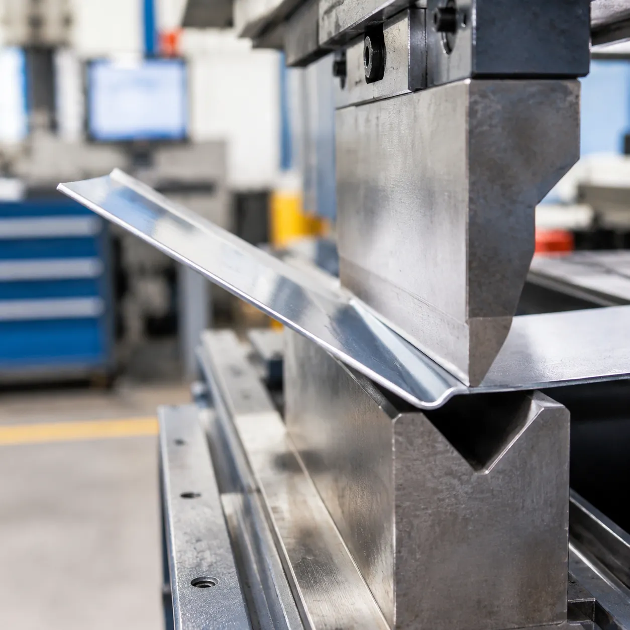
Setting the wrong press brake die clearance compromises part accuracy, ruins cosmetic finishes, and poses real safety hazards for your tooling and press brake. When the relationship between sheet thickness and V-die opening is off, forming forces shift unpredictably.
Risks of Undersized V-Openings
When the die opening is too narrow for the sheet thickness, the punch forces material into an overly restricted gap. We frequently see this result in several severe shop-floor failures:
- Tonnage Spikes: Bending force climbs rapidly. Forcing thick sheet into a narrow die can double or triple required tonnage, risking hydraulic overload.
- Tool Fracture: Excessive concentrated loads can snap punch tips, chip die shoulders, or permanently deform tooling seats.
- Sheet Surface Cracking: Extreme tensile stress on the outside of the bend stretches the metal past its ultimate tensile limit, leading to visible surface fractures.
Problems with Oversized V-Openings
Selecting a V-die opening that is too wide causes the opposite set of dimensional control issues:
- Irregular Inside Bend Radius: In air bending, the inside radius floats naturally. An oversized V-opening creates a much larger radius than specified on the print.
- Severe Springback Variations: Larger radii introduce higher elastic recovery. To maintain angle consistency across batches, pairing the right opening with proper press brake die angles for springback selection becomes mandatory.
- Flange Drop-Off: If the flange length is too short for a wide die opening, the sheet slips down between the die shoulders instead of forming cleanly against the stop.
Die Shoulder Friction and Cosmetic Marking
Incorrect press brake die clearance concentrates immense friction directly along the die entry radii. Tight openings scrape the workpiece against hard tool steel, stripping coatings and gouging bare sheet metal.
To eliminate heavy score marks on sensitive materials like polished stainless or aluminum, we recommend increasing the die opening ratio, maintaining polished die shoulder radii, and following regular press brake die maintenance tips to keep friction surfaces clean and free of galling.
Shop-Floor Strategies for Optimizing Press Brake Tooling Clearance
Getting consistent parts on the shop floor comes down to how we balance tool geometry, material behavior, and surface requirements during setup. Applying a few practical adjustments prevents unexpected tool wear and keeps bend angles reliable.
Matching Punch Tip Radius to Die Width to Prevent Sharp Creasing
When setting up your tooling, the punch nose radius must match the selected V-die opening width. If we use an overly sharp punch on a wide opening, the punch penetrates the material centerline before the sheet naturally wraps along the shoulders. This causes center creasing, alters the natural inside radius, and creates inconsistent bend angles.
- Avoid knife-edge penetration: Ensure the punch nose radius does not drop below natural air bend limits (roughly 60% of sheet thickness for mild steel).
- Maintain balanced clearance: Pair punches with appropriate precision-ground press brake V-dies to maintain a smooth contact arc across the die shoulders.
Managing Sheet Metal Grain Direction and Tensile Variations
Sheet metal behaves differently depending on how the blank is cut relative to its rolling direction:
- Bending with the grain (longitudinal): Increases the risk of outside cracking. We widen the die opening clearance slightly (often from 8x to 10x material thickness) to reduce stress on the outer bend fibers.
- Bending across the grain (transverse): Allows for tighter bend radii and standard die openings due to higher ductility.
- Tensile strength variations: Higher-strength batches generate more springback and demand wider die clearances to prevent sudden tonnage spikes.
Using Precision-Ground Acute Angle Dies and Surface Protection
When bending materials prone to springback or cosmetic defects, tool selection and friction control make a massive difference:
- Acute angle dies: Using 30-degree or 45-degree acute profiles from our standard press brake dies lineup gives enough stroke depth to overbend tough materials without bottoming out the tool clearance.
- Shoulder friction control: Applying urethane protective tape along the die shoulders cushions the contact point. This stops galling on stainless steel and aluminum while maintaining true die clearance dimensions.
Frequently Asked Questions About Press Brake Die Clearance
What happens if the V-die opening is too small for the material thickness?
Forcing sheet metal into an undersized V-die causes tonnage demand to spike exponentially. This increases the risk of overloading the press, cracking the punch tip, or splitting the die. A tight opening also leaves heavy contact marks on the part surface and can cause the material to fracture along the bend line. Checking your tool limits against our European press brake die rating guide for tonnage safety ensures you keep forming forces well within safe operating thresholds.
How does die clearance change when bending high-strength stainless steel?
High-tensile alloys and stainless steel exhibit greater yield strength and significant springback compared to standard mild steel. We recommend increasing the V-die opening from the standard 8x ratio to 10x or 12x the material thickness. This wider opening keeps tonnage requirements manageable and minimizes wear on your tooling setup. Choosing durable tool alloys detailed in our press brake die material guide provides extra resistance against the severe abrasion caused by high-strength materials.
Can you bend short flanges by simply reducing die clearance?
While dropping down to a smaller V-opening allows for a shorter minimum flange, it introduces major operational trade-offs:
Tonnage escalation: Every reduction in die width increases required bending force.
Flange slip: The sheet edge must cleanly span across both die shoulders; otherwise, it drops into the V-groove, resulting in crooked bends.
Surface damage: Concentrated pressure creates sharp drag lines along the bend radius.
What is the difference between air bending clearance and bottoming clearance?
| Feature | Air Bending Clearance | Bottom Bending Clearance |
|---|---|---|
| Die Ratio | 6x to 12x sheet thickness | Typically 5x to 6x sheet thickness |
| Tool Contact | 3-point contact (punch tip and 2 die shoulders) | Punch and die fully seat against the sheet |
| Tonnage Load | Low to moderate | 3x to 5x higher than air bending |
| Radius Control | Natural radius (~16% of V-opening) | Matches the punch tip nose radius |
| Springback | Higher (compensated by overbending) | Low (mechanically set by tool geometry) |