
Choosing the wrong tooling radius can instantly ruin a bend—leading to cracked parts, inaccurate angles, or damaged tools.
So, how do you get it right every single time?
In this guide, you're going to learn exactly how to select press brake punch radius step by step.
I'll break down the practical rules, material thickness ratios, and shop-tested formulas you need to produce flawless, precise bends on the very first try.
Let’s dive right in.
How Punch Radius Interacts with Bending Methods
Selecting the correct press brake punch radius is the single most critical decision we make when establishing a repeatable bending process. The punch nose radius does not act in isolation; its interaction with the sheet metal changes fundamentally depending on whether we air bend, bottom, or coin. Understanding these mechanics ensures we prevent structural failure, tool damage, and inconsistent bend angles across production runs.
| Bending Mode | Role of Punch Tip Radius | Inside Bend Radius Determinant |
|---|---|---|
| Air Bending | Guides the bend line and profile | Primarily governed by the V-die opening (floating radius) |
| Bottoming | Imparts the radius under pressure | Strongly influenced by punch tip radius and die geometry |
| Coining | Displaces material under very high tonnage | Closely conforms to the punch tip geometry |
Air Bending vs. Bottoming and Coining Mechanics
The choice of forming method dictates how directly the punch nose radius transfers to the finished part:
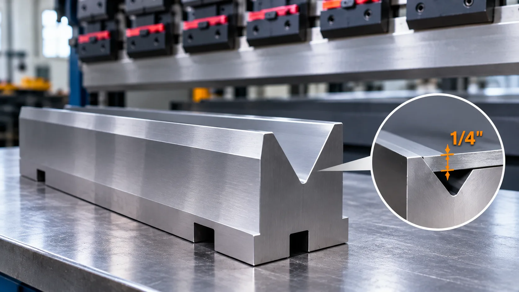
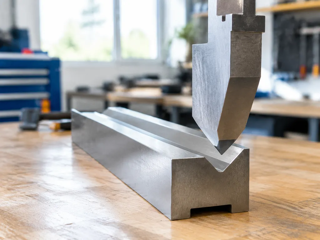
- Air Bending: The sheet contacts only three points: the punch tip and the two die shoulders. The punch radius guides the centerline of the bend, but the inside radius floats naturally based on die width.
- Bottoming: The punch drives the material down until it contacts the die faces at roughly 80% to 90% of the material yield point. The punch tip radius directly imprints onto the inner bend radius.
- Coining: The punch tip penetrates past the neutral axis under extreme tonnage, completely plastically deforming the material. The inside radius matches the punch nose radius identically, but tool wear and machine strain increase drastically.
How Natural Inside Radius Forms in Air Bending
In air bending, the inside bend radius does not automatically mirror the punch nose radius. Instead, the material forms a natural floating radius proportional to the V-die opening:
- The Die Ratio Rule: For standard carbon steel, the natural inside radius forms at roughly 15% to 17% of the V-die width.
- Punch Influence: As long as the punch tip radius is smaller than this natural floating radius, the sheet maintains its natural parabolic curve without being forced into shape.
- Profile Control: When we select a punch radius that matches the natural inside radius as closely as possible, we achieve the most stable, repeatable bend angles with minimal tonnage variance.
Understanding the Sharp Bend Threshold
The sharp bend threshold is the critical boundary where a punch tip becomes too narrow for the material thickness and die opening.
When the punch nose radius falls below the sharp bend threshold (typically below 63% of the natural floating radius in mild steel), the material can no longer maintain a smooth, uniform curvature. Instead of wrapping naturally around the tool, the applied tonnage focuses onto a razor-thin contact area, forcing the tool to act like a cutting edge rather than a forming profile.
Why an Undersized Punch Creases Instead of Bends
Using an undersized punch nose radius introduces severe forming defects that compromise part integrity:
- Localized Yield Failure: Extreme point-load stress pierces the surface, driving a hard crease into the inside bend line.
- Grain Structure Tearing: Creasing ruptures the outer tensile fibers of the sheet, causing micro-fractures, visible orange peel, or complete cracking along the bend line.
- Erratic Angular Springback: A creased bend disrupts the neutral axis displacement, leading to unpredictable springback variations from sheet to sheet.
- Accelerated Tool Fatigue: Concentrating bending loads onto a narrow punch tip accelerates nose deformation, chipping, and premature tool failure.
Key Factors When Selecting Press Brake Punch Radius
Selecting the right punch nose radius requires balancing your workpiece properties with your machine setup. When we set up jobs on the shop floor, we focus on four primary variables to avoid cracked parts, deformed profiles, or damaged tools.
| Factor | Key Concern | Punch Radius Adjustment |
|---|---|---|
| High-Strength Alloy | Low elongation / cracking | Increase radius (1.5 × t–3 × t) |
| Bending With Grain | Splitting along the bend line | Increase radius by at least 50% |
| Narrow V-Die | Tool bottoming & overload | Keep punch nose radius smaller than the natural air-bend radius |
| High Springback | Overbending requirement | Use appropriate punch radius and acute-angle tooling for springback compensation |
Material Type and Ductility Limits
A material's tensile strength and elongation limit determine how tight you can bend it before the outer fibers tear.
- Soft aluminum and mild steel: Highly ductile. They tolerate a punch tip radius equal to or smaller than the sheet metal thickness.
- Hardened alloys and stainless steel: Much lower elongation limits. They require a larger punch nose radius to distribute bending stress evenly across the bend zone and ensure sheet metal cracking prevention.
Sheet Metal Thickness and Grain Direction Effects
Sheet metal thickness directly drives your minimum bend radius, but grain direction dictates how forgiving the metal will be:
- Transverse Bending (Across the Grain): The strongest orientation. You can use standard, tighter punch nose profiles with minimal risk of cracking.
- Longitudinal Bending (With the Grain): Weakest orientation. The metal splits easily along structural grain boundaries. When forced to bend parallel to the grain, increase your punch nose radius by at least 50% to avoid orange peel texture and deep fractures.
V-Die Opening Relationship and Punch Bottoming Prevention
In air bending, your punch radius must work in harmony with your V-die opening ratio. If you pair an oversized punch radius with a narrow V-die, the punch nose will hit the die shoulders and bottom out before reaching your programmed angle, resulting in severe machine overload.
We always cross-reference our tool profiles against our press brake V-die chart and tonnage guide to verify that the punch profile clears the die cavity throughout the entire stroke.
Springback Behavior Across Different Alloys
Every metal pushes back after the tool releases pressure. Higher yield strengths produce more severe angular springback, requiring a modified punch radius selection:
- Mild Steel (A36, 1018): Low springback (0.5° to 1.5°). Standard punch radius sizing creates predictable inside radii.
- Stainless Steel (304, 316): Moderate-to-high springback (2° to 5°). Requires smaller tool radii and extra stroke depth to overcome work hardening.
- High-Strength Steels (Domex, Hardox): Severe springback (10° to 20°+). Demands larger punch radii to prevent fracture, paired with acute punch angles to achieve proper angular springback compensation.
Step-by-Step Rules to Calculate Punch Tip Radius
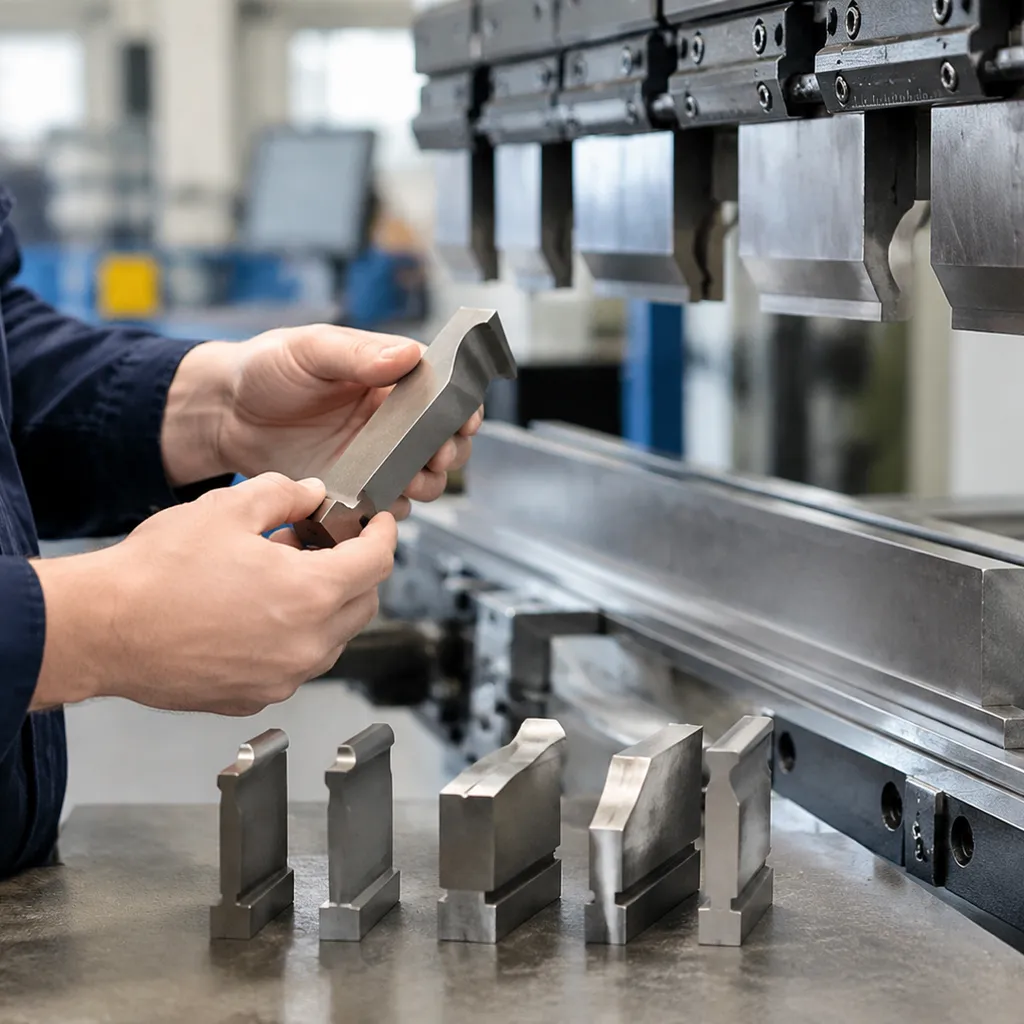
Choosing the correct press brake punch radius is not a guessing game. When I size tooling for a specific bending job, I follow a strict three-step calculation to protect parts from cracking and keep tooling from overloading.
Step 1: Determine Minimum Safe Bend Radius
Before picking a punch nose radius, establish the smallest radius the material can physically handle without tearing its outer fibers.
- Factor in sheet metal thickness (t): The minimum bend radius directly scales with thickness.
- Evaluate material ductility and tensile strength: Softer alloys bend tighter, while high-strength alloys need larger radii.
- Check the grain direction: Bending parallel to the grain requires a larger radius than bending across the grain.
| Material Type | Typical Safe Minimum Radius (Rₘᵢₙ) |
|---|---|
| Mild Steel (A36 / 1018) | 0.8 to 1.0 × t |
| Stainless Steel (304 / 316) | 1.0 to 1.5 × t |
| Aluminum (5052-H32) | 1.0 to 1.5 × t |
| Aluminum (6061-T6) | 2.5 to 4.0 × t |
If a punch radius is smaller than the minimum safe bend radius, the bend line will crease, exhibit orange peel, or crack completely.
Step 2: Balance Punch Radius with Natural Inside Radius
In air bending, the inside bend radius is primarily created by the V-die opening ratio, forming what we call the air bending natural radius.
- Calculate the Natural Inside Radius (Rᵢ):
- For mild steel, Rᵢ ≈ 15%–17% of the V-die opening (V).
- For stainless steel, Rᵢ ≈ 18%–20% of V.
- For soft aluminum, Rᵢ ≈ 13%–15% of V.
- Match Punch Nose Radius (Rₚ) to Rᵢ:
- Rₚ ≈ Rᵢ: Provides a close match between the punch nose and the expected natural bend radius.
- Rₚ < Rᵢ: Can be used provided the punch radius does not create an excessively sharp bend for the material.
- Rₚ > Rᵢ: The larger punch nose increasingly influences the resulting inside radius and may affect the required bending force and springback.
When heavy-gauge structural parts or large-radius profiles require a specific finished inside bend, we mount press brake radius punches engineered to match the required part geometry directly.
Step 3: Calculate Concentrated Tip Load and Tonnage Limits
A punch nose radius must also withstand the localized bending forces generated by the press brake. A narrow or sharp punch nose concentrates high pressure over a small contact area, increasing the risk of punch deformation or failure.
- Calculate Required Bending Tonnage (P):
P = (1.42 × Tensile Strength × t²) / V - Check Punch Shoulder and Tip Limits:
Every punch profile has a maximum rated load per foot or meter. Small tip radii (such as 0.8 mm or 0.030 in) typically have lower allowable load limits before deformation occurs. - Prevent Coining and Tool Yielding:
If the required tonnage exceeds the punch profile’s rated capacity, select a stronger or larger-radius punch and consider increasing the V-die opening to reduce the required bending force.
Recommended Punch Radius Guide by Material
Carbon Steel Thickness to Radius Guidelines
Mild carbon steel (such as A36, AISI 1008, or AISI 1018) offers predictable plastic deformation during air bending. As a standard rule of thumb, we pair standard mild steel with a punch radius equal to 0.8x to 1.0x sheet metal thickness.
When working with high-strength structural steels (such as Strenx or Hardox), ductility drops significantly. For these grades, you must increase the punch nose radius to at least 1.5x to 2.5x material thickness to distribute bending forces and prevent surface tensile cracking. When forming high-tensile stock, pairing these larger radii with heavy-duty press brake die sets for high-strength steel protects both the workpiece and the machine bed from concentrated load failure.
| Carbon Steel Type | Material Thickness (t) | Recommended Punch Radius (r) | Die Opening (V) Ratio |
|---|---|---|---|
| Mild Steel (A36/1018) | 0.5 mm – 3.0 mm | 1.0 mm – 3.0 mm (1.0 x t) | 6x to 8x t |
| Mild Steel (A36/1018) | 3.5 mm – 6.0 mm | 3.0 mm – 6.0 mm (1.0 x t) | 8x to 10x t |
| HSLA / Structural | 2.0 mm – 6.0 mm | 3.0 mm – 12.0 mm (1.5x – 2.0 x t) | 10x to 12x t |
Stainless Steel Work Hardening Adjustments
Austenitic stainless steels (such as 304 and 316) work-harden instantly upon contact with the punch tip. If you use an undersized, sharp punch, the extreme localized strain hardens the bend zone, leading to premature cracking, heavy grooving, and severe springback.
- Minimum Safe Radius: Maintain a punch nose radius of at least 1.0x to 1.25x sheet thickness for cold-rolled sheets.
- Heavy Plate Radii: Increase to 1.5x to 2.0x thickness for plate exceeding 3.0 mm to prevent the outer fiber from tearing.
- Springback Allowance: Stainless steel exhibits double the springback of mild steel. Choose an acute punch profile (such as 85° or 80°) with an adequate tip radius to overbend accurately.
For demanding production runs, tooling reliability is critical during dedicated stainless steel processing applications to combat the abrasive nature and high forming resistance of the material.
Aluminum Alloy Radius Requirements by Temper Grade
Aluminum alloys vary widely in bendability depending on their alloy series and heat treatment. Bending aluminum with a punch radius that is too tight causes visible "orange peel" textures, micro-fractures, or complete splits along the bend axis.
- 5052-H32 / 3003-H14 (Forming Grades): Excellent cold-forming properties. A punch radius of 1.0x material thickness delivers clean, repeatable bends across or along the grain.
- 6061-T6 (Structural Grade): High yield strength with low elongation. A minimum punch radius of 1.5x to 3.0x material thickness is mandatory. Bending along the rolling grain requires an even larger radius to avoid sudden rupture.
- 5083 / 2026 (High-Strength Alloys): Require a punch nose radius of 2.0x to 4.0x material thickness. Whenever possible, bend 90 degrees to the sheet rolling direction to maximize bend reliability.
Common Punch Radius Mistakes and How to Fix Them
Setting up a press brake with the wrong punch tip radius leads to scrap parts, inconsistent angles, and ruined tooling. We see these three mistakes on shop floors daily, and fixing them takes only minor tooling adjustments.
Using One Sharp Punch for Every Sheet Gauge
Leaving a single sharp punch (like a 0.8 mm / 0.030" tip) loaded in the brake for every gauge creates serious quality issues. When we push a narrow punch tip into heavier plate:
- The material creases: The punch penetrates past the yield point before forming a clean curve, creating a visible fracture groove on the inside radius.
- Tooling wears out fast: High concentrated loads dull the tip edge and risk chipping.
- The Fix: Match your punch nose radius to the material thickness. Swap to dedicated precision press brake punches with tip radii matched to at least 63% to 80% of your sheet thickness to form natural, crack-free bends.
Oversized Punch Radius and Unpredictable Springback
Choosing a punch radius significantly larger than the natural air-bend radius creates broad, loose contact between the sheet and the tool:
- Inconsistent bend angles: Excessive surface contact multiplies angular springback, making angle compensation difficult across different sheet metal batches.
- Side-to-side variation: The sheet can drift off-center inside the V-die before full bottoming occurs.
- The Fix: Keep the punch nose radius slightly below or equal to the naturally formed inside bend radius during air bending. If your print demands a large inside radius, increase your V-die opening proportionally or use specialized radius inserts to stabilize the bend.
Overloading Acute and Narrow Tool Profiles
Narrow profile punches give you extra clearance for deep return flanges, but their smaller cross-sectional area makes them vulnerable to structural failure:
- Tip deformation: Running high-tonnage jobs on narrow tool tips causes permanent deflection and center sagging along the bed.
- Tool breakage: Exceeding maximum load limits on acute angles risks catastrophic tool splitting.
- The Fix: Always calculate the concentrated load per meter or foot before running high-strength steel or thick plate. When deep clearance or tight pre-bends are required, use properly rated acute punches built to handle the required tonnage without exceeding tool yield limits.
Selecting Tooling Profiles for Specific Bending Jobs
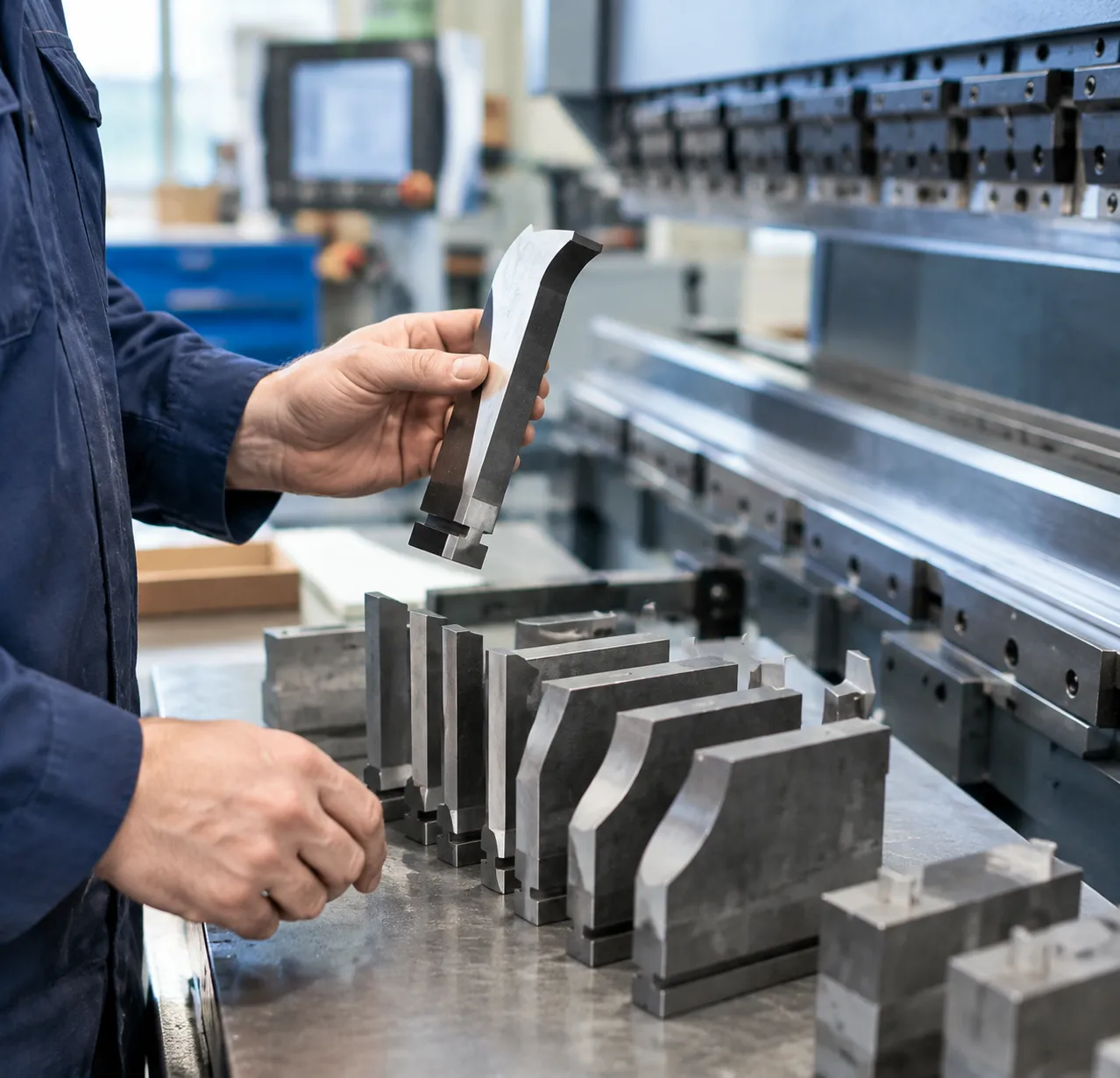
Matching your punch nose radius to the right structural tool profile prevents physical collisions, tool deformation, and part rejection. Tool geometry dictates clearance, while the punch radius determines the inside bend radius and load distribution.
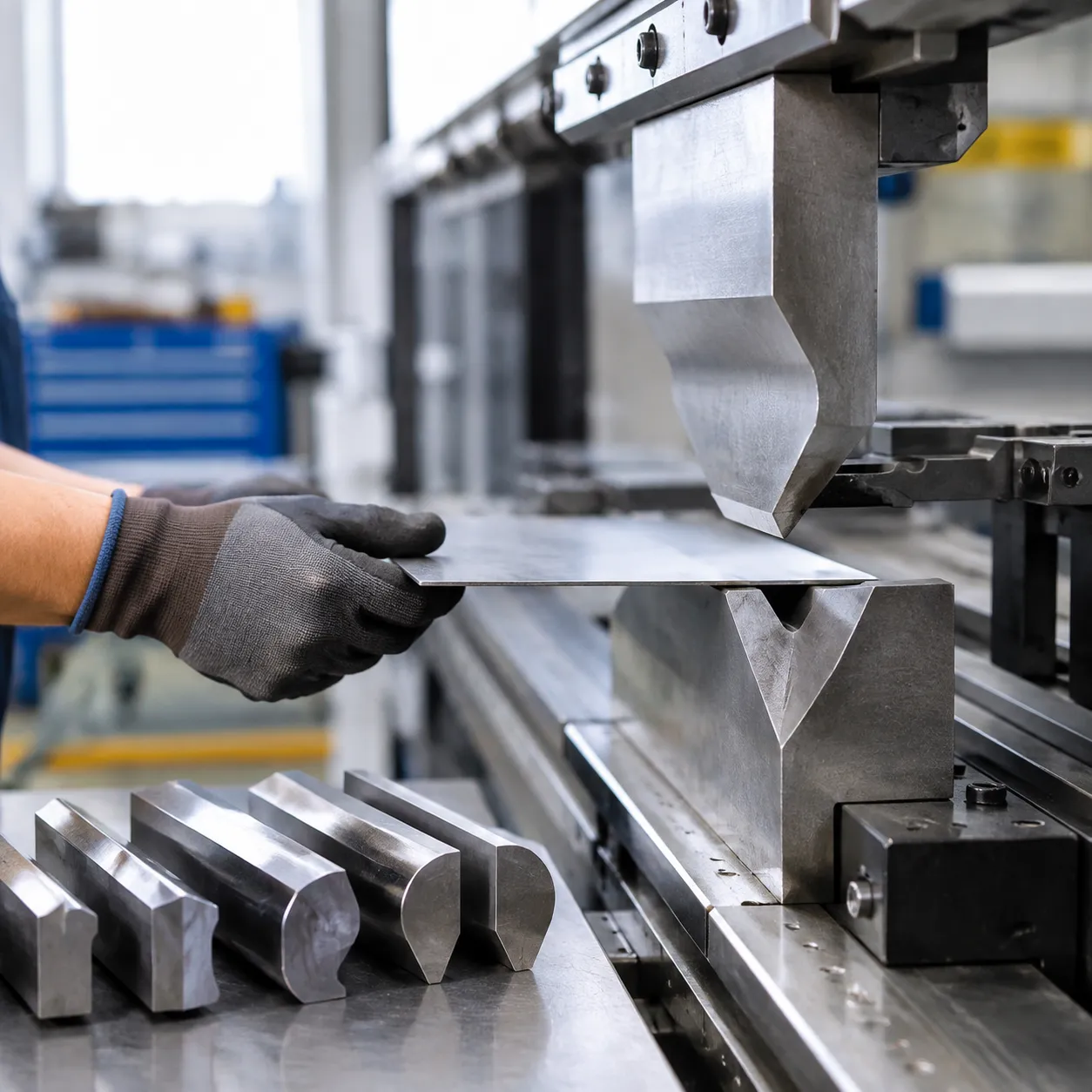
Straight, Sash, and Gooseneck Punch Radius Applications
Different profile geometries handle specific bend sequences and clearance requirements:
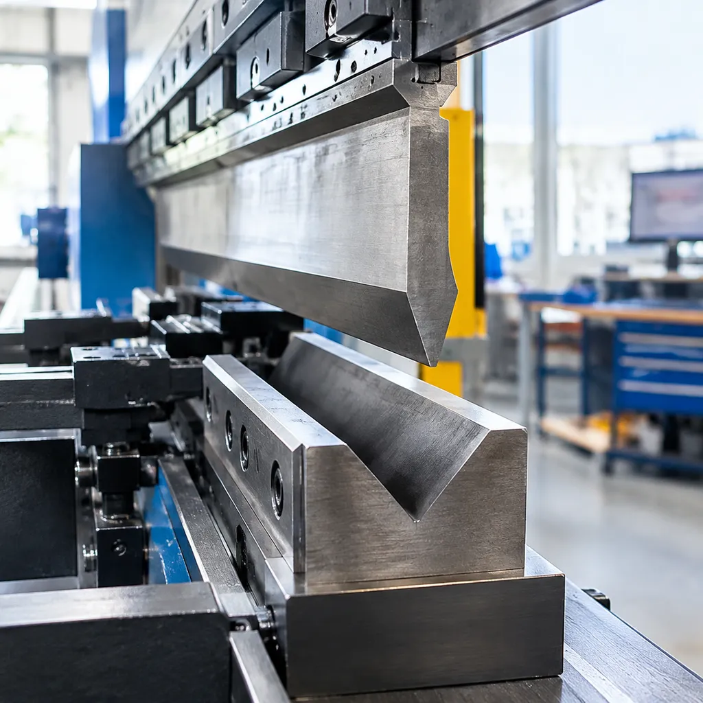
- Straight (Standard) Punches: Deliver the highest structural rigidity and tonnage capacity. We use these for high-tonnage jobs and simple 90° bends where clearance around previous flanges is not a constraint.
- Sash (Acute/Narrow) Punches: Designed with a slim profile to clear tight return bends and deep channels. Because the narrow body handles lower tonnage, avoid using extremely sharp punch radii that focus stress onto the slim neck.
- Gooseneck Punches: Feature a recessed throat designed to clear return flanges on complex profiles. Pair gooseneck profiles with a punch radius large enough to prevent localized creasing while respecting the tool's rated centerline tonnage limits.
| Punch Profile | Typical Punch Nose Radius | Best Application | Primary Shop-Floor Consideration |
|---|---|---|---|
| Straight / Standard | 0.030" – 0.250" (0.8mm – 6.35mm) | General sheet metal fabrication, high-tonnage bending | Max load capacity; lowest risk of tool deflection |
| Sash / Acute | 0.008" – 0.060" (0.2mm – 1.5mm) | Narrow channels, tight U-profiles, pre-hemming | Limited tonnage; high risk of neck cracking if overloaded |
| Gooseneck | 0.030" – 0.125" (0.8mm – 3.2mm) | Multi-bend parts, return flanges, deep boxes | Off-center loading; strictly monitor side-thrust and tonnage |
Precision Ground Tooling for Repeatable Radii
Punch radius accuracy directly impacts your bend angles during air bending. Conventional planed tooling often carries slight dimensional variations along the tool length, leading to inconsistent natural inside radii and uneven springback across long parts.
We rely on precision ground European-style press brake tooling manufactured to tight tolerances. Precision ground punches ensure that:
- The tip radius remains completely uniform from end to end, eliminating angular variation across long bends.
- Tool centers align instantly on multi-station setups without manual shimming or constant recalibration.
- Bend deduction and bend allowance calculations remain reliable across consecutive production runs.
When to Choose Custom Radius Tooling
Standard punch nose radii stop meeting engineering specs when jobs involve large inside radii, heavy plate, or sensitive alloys that crack under conventional tooling.
Investing in custom press brake tooling becomes essential under the following conditions:
- Replacing Step Bending: Forming a large radius via multi-break bump bending adds excessive cycle time and creates visible score lines. A dedicated large-radius punch produces smooth, single-stroke bends in high-volume production.
- Heavy-Plate Forming: Bending high-yield structural steels requires oversized, hardened punch radii to avoid exceeding the material's minimum safe bend radius and causing grain fracture.
- Cosmetic and Non-Marking Demands: Custom punches with tailored nose geometries prevent surface galling on polished stainless steel or pre-painted architectural panels.
Frequently Asked Questions
What happens if the press brake punch radius is too small?
When you use an undersized punch tip, the tool pierces and creases the sheet instead of creating a smooth, contoured bend. Operating below the sharp bend threshold causes severe shop-floor issues:
Outer fiber fracture: Tensile stress exceeds the material's ultimate limit, causing visible cracking or part failure along the outer radius.
Accelerated tool wear: Concentrating machine tonnage onto a razor-thin punch nose degrades the precision ground tip, leading to premature chipping and deformation.
Inconsistent bend angles: Deeply creased parts resist natural air-forming dynamics, making angular consistency across production runs impossible.
How does punch radius affect bend deduction and bend allowance?
Inside bend radius directly dictates how much the metal stretches and shifts along its neutral axis during forming. A larger punch nose radius produces a wider inside radius, which:
Increases the total bend allowance (the actual arc length along the neutral axis).
Reduces the bend deduction value required for your flat blank layout.
When we dial in flat blank calculations, any change to punch nose geometry shifts the neutral axis ($k$-factor). Setting the proper punch radius ensures flat patterns fold to exact finished print dimensions, particularly when referenced alongside our press brake die clearance guide for better bending.
Can you use a punch radius larger than the material thickness?
Yes, using a punch radius larger than the material thickness is standard practice for high-strength materials, cosmetic parts, and heavy plate forming.
- High-strength alloys: Steels with high yield strengths require punch radii 2× to 5× their sheet thickness to prevent catastrophic splitting.
- Cosmetic forming: Broad radii minimize surface marring, scoring, and die witness lines on architectural panels.
- Springback considerations: Larger punch radii generate significantly more angular springback. You must account for additional overbending stroke and pair the punch with an appropriately wide V-die opening to maintain clearance.
How do you prevent aluminum from cracking along the bend line?
Forming aluminum alloys like 5052-H32 or 6061-T6 requires specific adjustments to avoid cracking and "orange peel" grain separation:
Bend across the grain: Always orient critical bend lines perpendicular (transverse) or at a 45-degree angle to the sheet rolling direction.
Increase the punch tip radius: For hardened tempers like 6061-T6, maintain a punch radius at least 1.5× to 3× the sheet thickness.
Widen the bottom die: Use a V-die opening ratio between 10× and 12× material thickness to reduce forming strain.
Anneal the bend zone: If a design demands a tight radius on high-temper aluminum, apply localized heat along the bend axis prior to forming to restore material ductility.