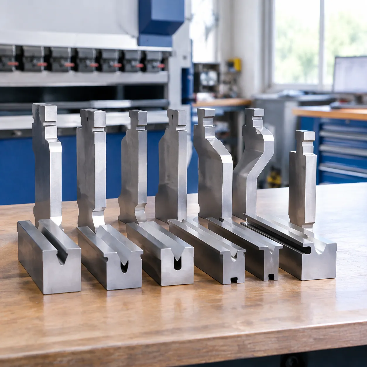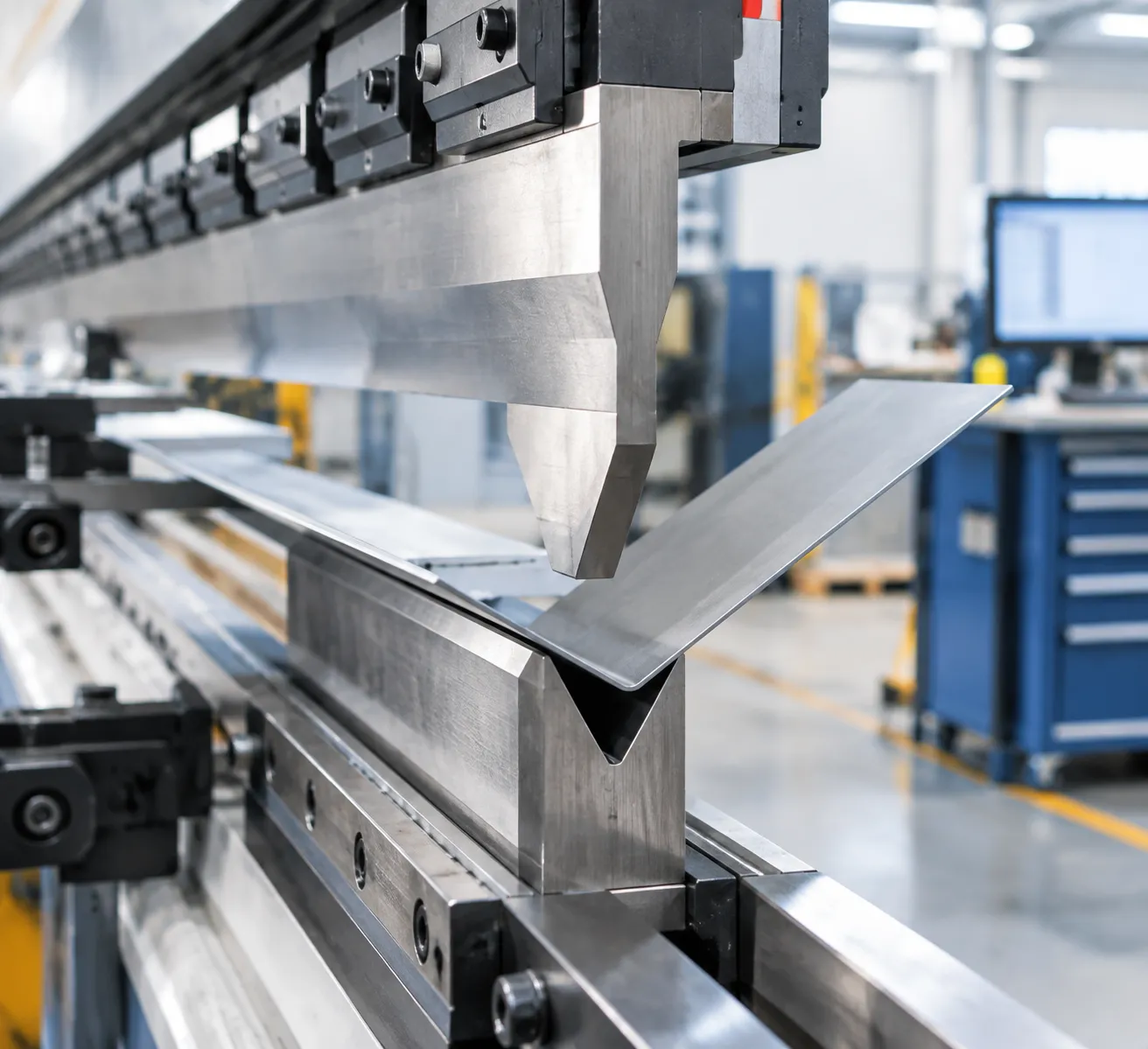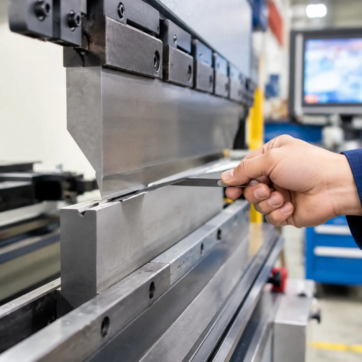
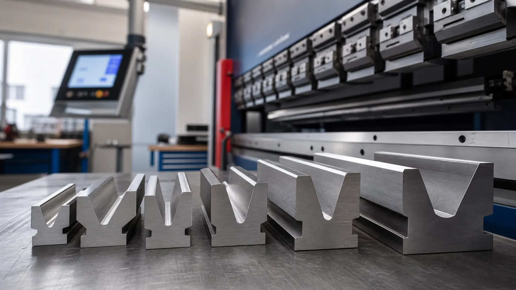
Correct die selection is the single most important factor in achieving precise bends while protecting your machine and tooling. Referencing a reliable press brake v die chart cuts out the guesswork before you hit the foot pedal.
Core Mechanics of Press Brake V-Die Selection
V-Opening, Tonnage, and Bend Radius
The width of your lower die opening (V) directly controls forming force requirements, part geometry, and material strain:
- Narrow V-Openings: Dramatically increase required machine tonnage, create tighter inside bend radii, and concentrate material strain (raising the risk of surface cracking).
- Wider V-Openings: Significantly lower the required tonnage load and ease material strain, but produce larger inside radii and demand longer minimum flange lengths.
Bending Method Comparison
| Forming Method | Die Opening Ratio | Tonnage Load | Inside Bend Radius (Ri) Control |
|---|---|---|---|
| Air Bending | 8xT (Standard baseline) | Low | Formed naturally by die width (~16% to 20% of V) |
| Bottoming | 5xT to 6xT | Moderate (3x to 5x higher than air bending) | Forced to match punch tip radius under load |
| Coining | 4xT to 5xT | High (8x to 10x higher than air bending) | Permanently stamped to punch tip geometry |
The "Rule of 8" (8T) Baseline Explained
In standard air bending operations, V = 8 x T (where V is lower die width and T is sheet thickness) serves as the universal baseline on every standard press brake die chart for mild steel (tensile strength ~420 MPa). It delivers the ideal balance between acceptable tonnage loads and clean bend geometry.
When to Depart from the 8T Rule
Drop Down to 6T (V = 6 x T)
- Thin Sheet Metal: Required when forming tight inside bend radii on thin gauges.
- Short Flanges: Keeps narrow flanges from slipping into the V-groove during rotation.
- Note: Using 6T increases required bending tonnage by approximately 33%.
Expand to 10T - 12T (V = 10 x T to 12 x T)
- Heavy Plate Forming: Essential for thick structural steel plate.
- High-Tensile Materials: Prevents outer-radius fracturing on high-yield alloys (e.g., Hardox, Domex, Stainless Steel).
- Tonnage Management: Dramatically reduces tonnage per meter to keep heavy jobs within machine capacity limits.
Master Press Brake V-Die & Air Bending Tonnage Reference Chart
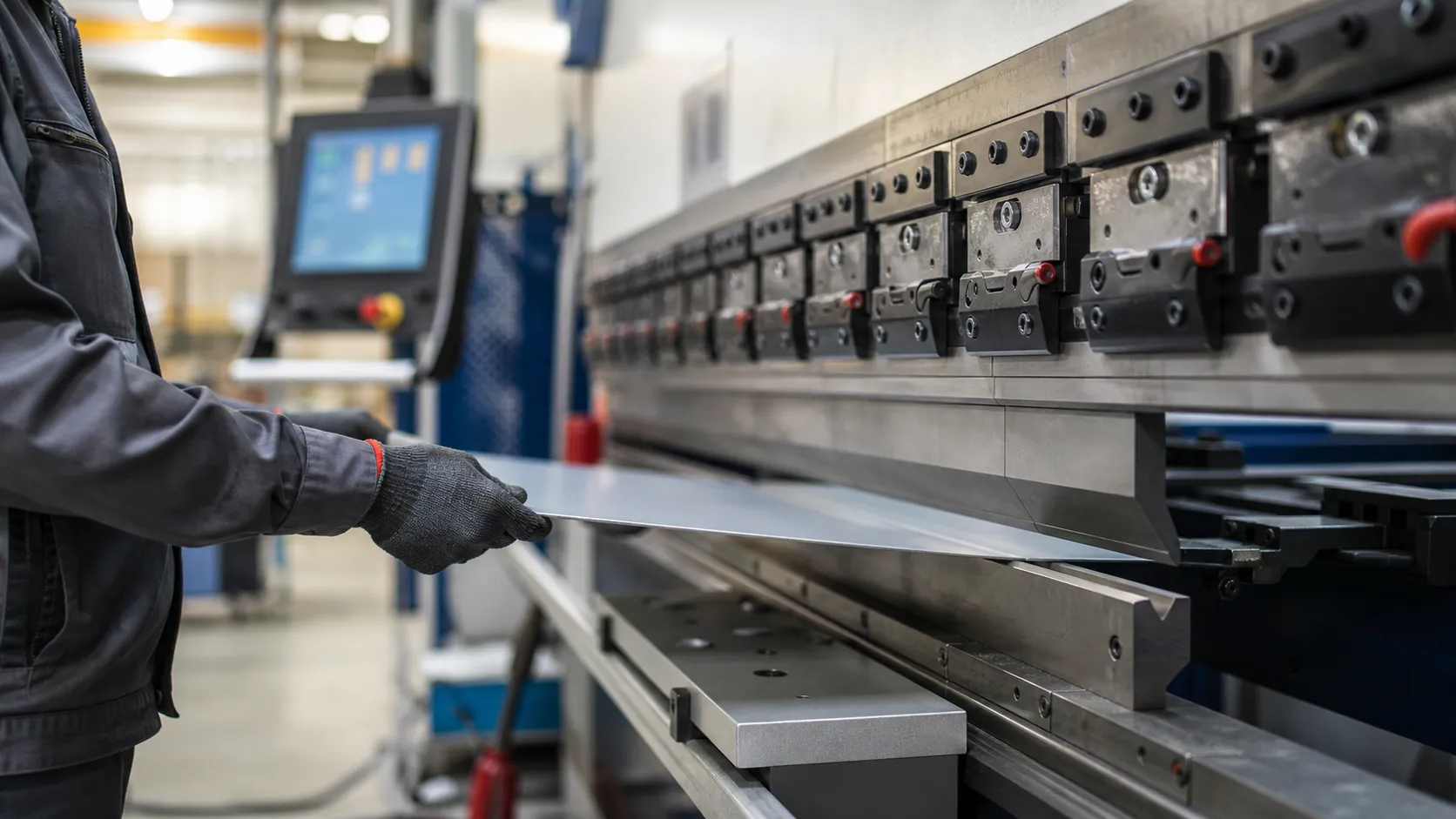
Comprehensive Shop-Floor Reference Table
The data below applies to standard air bending of mild steel with a tensile strength of 420 MPa. When shifting between different sheet metal thickness (T) values, paired V-groove choices directly determine the resulting inside bend radius (Ri), minimum flange length calculation (Fmin), and force demand per meter. Pair these values with proper precision radius punches to avoid material creasing.
| Sheet Thickness (T) | Recommended V-Opening (V) | Inside Bend Radius (Ri) | Minimum Flange Length (Fmin) | Recommended Punch Tip Radius | Required Tonnage per Meter (Mild Steel 420 MPa) |
|---|---|---|---|---|---|
| 0.8 mm / 22 GA | 6 mm | 1.0 mm | 4.2 mm | 0.8 mm | 5 T/m |
| 1.0 mm / 20 GA | 8 mm | 1.3 mm | 5.5 mm | 1.0 mm | 6 T/m |
| 1.5 mm / 16 GA | 12 mm | 2.0 mm | 8.5 mm | 1.2 mm | 11 T/m |
| 2.0 mm / 14 GA | 16 mm | 2.6 mm | 11.5 mm | 1.6 mm | 15 T/m |
| 3.0 mm / 11 GA | 25 mm | 4.0 mm | 17.5 mm | 3.0 mm | 22 T/m |
| 4.0 mm / 8 GA | 32 mm | 5.0 mm | 22.5 mm | 4.0 mm | 30 T/m |
| 6.0 mm / 1/4" | 50 mm | 8.0 mm | 35.0 mm | 5.0 mm | 45 T/m |
| 10.0 mm / 3/8" | 80 mm | 13.0 mm | 56.0 mm | 8.0 mm | 75 T/m |
For high-mix setups switching across gauge ranges, using a 10-way multi-V die eliminates constant tooling teardowns while covering these recommended V-widths.
Quick Reference Multiplier Matrix by Material Type
To adapt this press brake v die chart to non-standard metals, apply these correction factors directly to your baseline tonnage and V-opening selection:
- Mild Steel (420 MPa): Baseline Factor (1.0x). Follows standard 8T v-die opening ratio rules.
- Stainless Steel 304/316 (650–700 MPa): Tonnage Factor (1.5x). Use a recommended V-opening of 10T to reduce stainless steel bending tonnage spikes and prevent shoulder galling.
- Soft Aluminum (200 MPa): Tonnage Factor (0.5x). Use a recommended V-opening of 6T to achieve tighter profiles without overloading tooling.
- High-Yield Alloys (Hardox / Domex): Tonnage Factor (2.0x – 2.5x). Extend V-openings to 10T – 12T to lower severe machine loads and prevent acute tooling fracture.
Mathematical Formulas for V-Die Selection & Bending Force
Calculating required tonnage before setting up the machine saves tooling, protects your ram, and guarantees consistent bend angles.
Air Bending Tonnage Formula
To calculate the required force in metric tons (P) for air bending, we use this practical shop formula:
P = (1.54 * Rm * T^2 * L) / (V * 1000)
- P = Required force (tons)
- Rm = Material tensile strength in MPa (e.g., 420 for mild steel, 700 for stainless steel)
- T = Sheet metal thickness (mm)
- L = Bend length (mm)
- V = V-die opening width (mm)
Notice that the V-die opening (V) sits in the denominator. Opening up your V-die width directly reduces the tonnage required to form a part. Overloading narrow dies accelerates shoulder wear, so calculating tonnage accurately is crucial to maintaining your press brake V-die lifespan.
Predicting Air-Bent Inside Bend Radius (Ri)
In air bending, the punch does not press the material completely to the bottom of the die. Instead, the sheet floats across the die shoulders, naturally forming its own inside bend radius (Ri) based on the V-opening width:
- Mild Steel & Soft Aluminum: Ri is approximately 16% of V (e.g., a 16 mm V-opening yields an inside radius of roughly 2.5 mm).
- Stainless Steel & High-Tensile Alloys: Ri is approximately 20% of V due to higher material yield strength.
Shop Floor Rule: Swapping to a smaller punch tip radius will not decrease your inside bend radius during air bending. The sheet forms its natural radius dictated purely by the V-die opening width. The punch tip radius only alters the final inside radius if the punch tip radius itself is larger than the calculated Ri.
Cross-referencing these calculations against your press brake die chart ensures your machine tonnage stays within safe operational limits while meeting exact design tolerances on every run.
Geometric Constraints: Preventing Workpiece & Tooling Failure
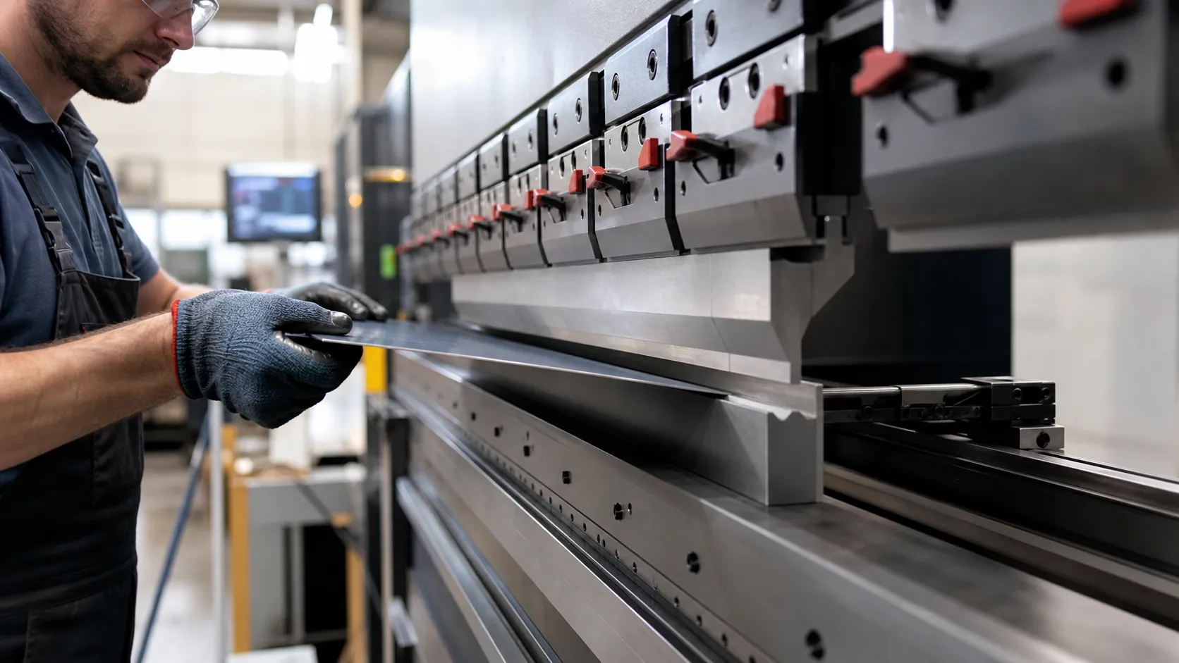
Minimum Flange Length Calculation
When consulting a press brake v die chart, minimum flange length is a critical physical boundary you cannot ignore. If a workpiece flange is too short, the sheet metal won't properly span both shoulders of the lower die during the initial stage of the bend.
- The Mathematical Rule: Minimum Flange Length (Fmin) ≈ 0.7 x V (typically 70% to 75% of the V-die opening width).
- The Risk of Short Flanges: When a flange is shorter than 70% of the die opening, it loses shoulder support and drops directly into the V-groove as the punch descends. This results in severe angular distortion, inconsistent bend lines, and heavy scarring on die edges.
For tight flange requirements where standard clearances are tight, selecting precision-machined standard V-dies with optimized shoulder radii helps maintain proper workpiece support without sacrificing accuracy.
Avoiding Tonnage Overload & Tool Cracking
Forcing high tonnage into an undersized V-die creates concentrated stress that can split hardened tool steel. We always check our reference press brake die chart to verify maximum load limits per meter (T/m) before setting up a job.
- Single V-Die vs. Multi-V Support: Single V-dies deliver high precision for standard sheet metal thickness, but high-tonnage heavy plate forming requires substantial structural backup. Utilizing heavy-duty multi-V die blocks helps distribute tonnage loads evenly across the press bed.
- Concentrated Load Hazards: Forcing thick plate into a narrow V-die dramatically increases required tonnage per meter. The punch acts as a wedge, generating extreme side-thrust forces inside the die pocket that can crack tooling shoulders or damage the machine bed. Always increase the V-opening when working with heavy plate or high-tensile materials to keep forming tonnage within safe operating limits.
Tooling Style Selection & Metallurgical Specifications
Matching your tooling to your machine system and material quality is just as crucial as checking a press brake v die chart. The wrong mounting style or soft die shoulders lead to premature wear, angle variations, and costly setup delays.
Clamping System Compatibility & Die Styles
We manufacture tools to fit seamlessly across global machine standards, eliminating the need for custom adapters on the shop floor. Whether running European Precision Style, American Traditional Style, or systems requiring WILA tooling compatibility and TRUMPF tooling, keying into proper alignment protects your ram and bed from uneven loads.
| Die Style | Best Use Case | Setup Speed | Production Flexibility |
|---|---|---|---|
| Single V-Die | Precision short runs, acute bends, tight clearances | Fast | Specific to target sheet thickness |
| Double V-Die | Standard job shop work with frequent thickness flips | Medium | Flips quickly between two V-widths |
| Multi-V Die Block | Heavy plate forming & high-mix fabrication | Moderate | Wide range of V-openings in one block |
The CAMT Precision & Quality Standard
Tool geometry must remain perfectly stable under extreme hydraulic force. When consulting your press brake die chart, account for how precision-ground surfaces and heat treatment hold tolerance during long production runs:
- Dimensional Tolerances (±0.01 mm): We precision-grind die shoulders to ±0.01 mm tolerances. This prevents angle variance and twisting along long sheet lengths.
- Induction Hardening (HRC 55–60): Deep localized induction hardening along the V-die shoulders resists galling and crushing forces, ensuring the V-opening stays exact over hundreds of thousands of bends.
- Ultra-Smooth Surface Finish (Ra < 0.8 µm): Polishing the V-groove entry radii to Ra < 0.8 µm minimizes die drag marks on sensitive architectural panels, polished stainless steel, and soft aluminum.
Practical Troubleshooting: Solving Complex Bending Challenges
Handling Excessive Springback in High-Tensile Steels
High-yield materials like Hardox, Domex, and high-tensile stainless steel exhibit heavy springback after unloading. Standard 88° or 90° dies fail to hold a true 90° angle because the material snaps back several degrees once pressure releases.
- Utilize Acute Angle Dies: Switch to 30°, 45°, or 60° acute dies to deliberately overbend the sheet, allowing elastic recovery to bring the part right to the target angle.
- Adjust V-Width: Pair acute punch profiles with slightly wider V-openings (10T to 12T) to reduce tonnage load and manage springback predictably.
- Match Tooling Styles: Review our precision-ground press brake tooling lineup to select hardened acute dies built for high-tonnage overbending.
Eliminating Die Marking on Polished Workpieces
Forming polished stainless steel, architectural aluminum, or pre-painted sheet metal often leaves gouges and shoulder contact lines. Inspect your press brake die chart parameters and apply these anti-marking solutions:
| Anti-Marking Strategy | Implementation | Practical Benefit |
|---|---|---|
| Urethane Protective Film | Lay high-durability film across the die face before bending | Blocks direct metal-to-metal contact; fast and flexible |
| Large-Radius Shoulder Dies | Dies engineered with smooth, oversized shoulder radii | Spreads surface pressure to prevent dragging and scoring |
| Non-Marking Roller Inserts | Rotatable composite inserts or spring-loaded shoulder die blocks | Eliminates surface friction on mirror-finish panels |
Bending Close to Holes and Slots
When punched holes or laser-cut features sit too close to the bend line, material stretches into the open V-die gap, distorting round holes into ovals.
- Deformation Zone Boundary: Keep hole edges at a minimum safe distance using the practical rule: Minimum Distance = (2 x T) + (V / 2), where T is sheet thickness and V is die opening width.
- Process Workarounds: If design constraints place holes inside the deformation zone, punch features post-bending, add relief slots, or consult our team for custom press brake tooling engineered with specialized relief geometry.
Custom Tooling Solutions: When standard press brake v die charts fall short
Standard press brake v die chart references work great for routine 90-degree bends. However, when your prints call for deep-box forming, tight offset channels, severe return bends, or custom radius profiles, standard selection tables hit a wall. Forcing standard die openings on complex geometries often leads to tool collisions, localized stress fractures, or scrapped parts.
When off-the-shelf tooling and basic press brake die chart guidelines aren't enough, we step in with specialized custom tooling development designed around your specific machine setup, clamping system, and production requirements.
CAMT Engineering & 3D Bending Simulation Workflow
We take the guesswork out of complex press brake setups by validating your tooling geometry virtually before running steel on our grinders.
- Step 1: CAD File Review & Bend Sequence Analysis: We review your 2D DXF/DWG and 3D STEP files to verify bend order, material stretch, and relief cut clearances.
- Step 2: Tonnage & Collision Risk Evaluation: Our engineering team runs full 3D bending simulations to calculate required forming forces and identify interference hazards between the workpiece, ram, and die bed.
- Step 3: Tool Profile Optimization: We customize V-opening widths, design special acute angles, and set staged tool heights to execute intricate shapes in fewer hits.
- Step 4: Precision Manufacturing & QA Traceability: Every custom die is precision-ground and deep induction hardened, backed by full quality assurance—including CMM optical measurements and Rockwell hardness certification.
Direct Engineering Consultation
You don't have to guess whether a non-standard job will clear your tool holders or strain your machine's tonnage limits. Our team provides direct technical support to review your drawings, optimize your bending parameters, and deliver reliable custom tooling built to your exact specifications.
Frequently Asked Questions (FAQs)
How do I choose the correct V-die opening for press brake bending?
I always recommend starting with your material thickness (T) and cross-referencing it with an official press brake v die chart. For baseline mild steel applications, apply the standard 8T rule (V = 8 × T). From there, evaluate your required inside bend radius, minimum flange length, and machine tonnage limits. If you are setting up new equipment or working with specialized clamping systems, check out our comprehensive guide on how to choose press brake tools to ensure total tooling compatibility.
What happens if I use a V-die opening that is too small or too large?
Selecting the wrong die width directly impacts part quality, machine wear, and shop safety.
| Die Opening Choice | Primary Effects on Bending | Key Shop-Floor Risks |
|---|---|---|
| Too Small ($V < 6T$) | • Exponentially increases required tonnage • Shrinks inside bend radius | • Tooling breakage or die shoulder cracking • Severe deep die marking on sheet surface |
| Too Large ($V > 12T$) | • Significantly lowers required tonnage • Increases inside bend radius | • Excessive springback and poor angular accuracy • Wider dimensional tolerances across long bends |
How do I calculate required press brake tonnage for stainless steel vs mild steel?
You can calculate force using the standard air bending formula:
$Tonnage (P) = \frac{1.54 × R_m × T² × L}{V × 1000}$
- Mild Steel (R_m \approx 420 MPa): Serves as the standard baseline (1.0×) on any standard press brake die chart.
- Stainless Steel (R_m \approx 650--700 MPa): Requires roughly 1.5× more tonnage than mild steel for the same sheet thickness.
When working with tough stainless grades, we usually expand the V-opening to $10T$ to keep tonnage within safe machine limits. Learn more about optimal parameters in our dedicated guide on stainless steel processing and bending.
What is the 8T rule in sheet metal forming and when should I break it?
The 8T rule states that the lower V-die opening width should equal 8 times the material thickness (V = 8 × T). It delivers the ideal balance between manageable bending tonnage and a clean inside radius for mild steel.
When to break the 8T rule:
Use $6T$ Opening: When forming thin sheet metal, requiring tight inside radii, or bending short leg flanges.
Use 10T--12T Opening: When forming heavy plate, high-tensile alloys, or stainless steel to prevent machine overload and excessive die wear.
Why do my bent parts fall into the V-groove during forming?
Your material drops into the die because the part flange length is smaller than the minimum required flange length (F_{min}).
- The Golden Rule: F_{min} must be at least 70% to 75% of the V-die opening width (F_{min} \approx 0.7 × V).
- The Fix: If your flange leg is too short, the sheet loses support on the die shoulders before the punch finishes its stroke. Switch to a narrower V-die (if tonnage allows) or use specialized acute/insert tooling to support short flanges.
Related Sources
- https://www.thefabricator.com/thefabricator/article/bending/press-brake-bending-tips-for-forming-tapered-bends-and-
- https://www.mate.com/product/press-brake-tooling/mate-cleanbend-forming-technology/
- https://www.thefabricator.com/thefabricator/article/bending/four-steps-to-calculate
- https://www.bystronic.com/zaf/en/news/how-calculate-press-brake-tonnage
- https://www.thefabricator.com/thefabricator/article/bending/four-steps-to-calculate-press-brake-tonnage-limits