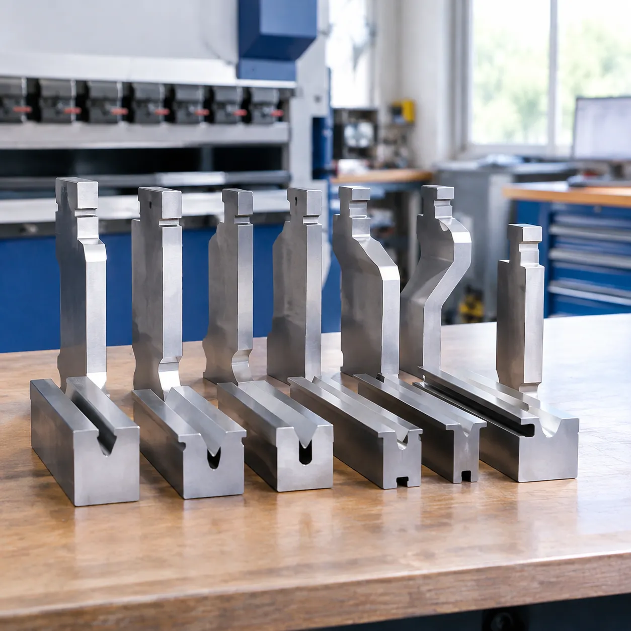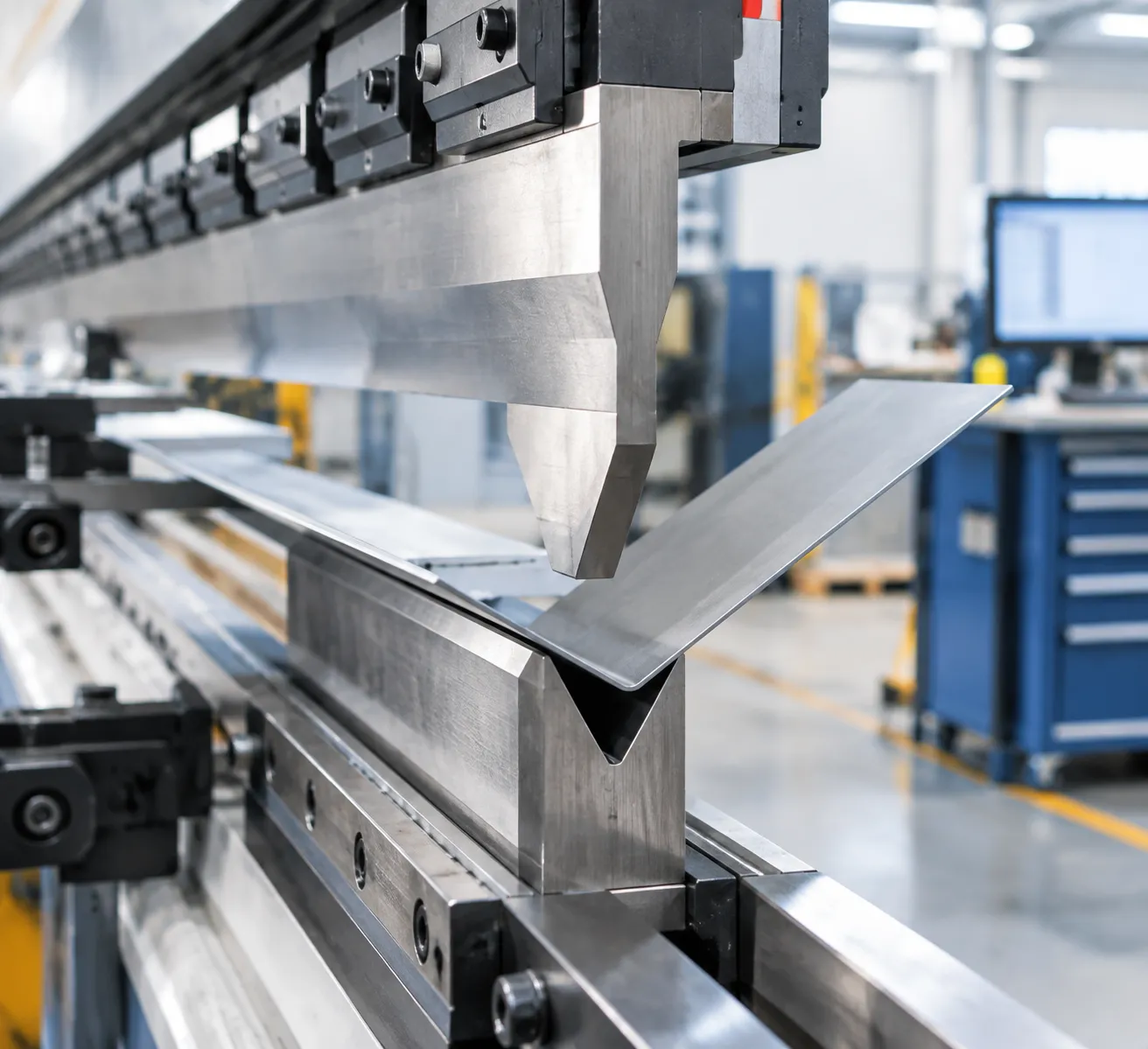
Pushing your tooling past its limit can split an expensive die in a split second—especially when converting a european press brake die rating from metric to imperial units.
Whether you need to translate kN/m to tons/ft, apply the Rule of 8 for V-die sizing, or enforce the 80% safety rule to avoid micro-fractures, knowing your exact load limits is critical to shop floor safety and precision bending.
In this guide, you’ll learn how to accurately calculate die tonnage capacity, select high-performance steel grades like 42CrMo, and protect your European precision-ground tooling from costly overload damage.
Let’s dive right in.
Understanding European Press Brake Die Rating
Load Capacity Units: kN/m, t/m, and Tons/Foot
Die manufacturers express die load capacity using metric kilonewtons per meter (kN/m) or metric tons per meter (t/m). In contrast, U.S. metal fabricators evaluate machine and die capacity in short tons per foot (tons/ft).
To prevent catastrophic overload, we use standard unit conversions to translate metric limits into shop-floor terms:
| Metric Unit | Standard Conversion | U.S. Imperial Equivalent |
|---|---|---|
| 1 t/m (Metric Ton/Meter) | 1 t/m = 9.81 kN/m | 0.3005 U.S. tons/ft |
| 1 kN/m (Kilonewton/Meter) | 1 kN/m = 0.102 t/m | 0.0306 U.S. tons/ft |
| 1 U.S. ton/ft | 1 U.S. ton/ft = 3.328 t/m | 32.65 kN/m |
Quick Reference Formulas:
- Convert kN/m to U.S. tons/ft: Rating in kN/m × 0.0306
- Convert t/m to U.S. tons/ft: Rating in t/m × 0.3005
- Convert U.S. tons/ft to kN/m: Rating in tons/ft × 32.65
Machine Tonnage Rating vs. Tooling Load Limit
A dangerous mistake in sheet metal fabrication is assuming a die can withstand whatever force the press brake ram delivers. Machine tonnage represents total available hydraulic force across the full bed length, whereas the tonnage limit per meter specifies the localized physical limit of the tool steel.
Overlooking this distinction causes point-loading failure:
- The Setup: Bending a short part on a heavy-duty press brake using a standard European V-die rated at 80 t/m (approx. 24 U.S. tons/ft or 785 kN/m).
- The Math: If your workpiece is 200 mm (0.2 meters) long, the actual total force the die shoulder can accept over that section is:
$Maximum Allowable Load = 80 t/m × 0.2 m = \mathbf{16 metric tons}$ - The Hazard: Bending this part on a 150-ton machine without setting force limits will direct excess force into a tiny footprint. Exceeding 16 tons over that 200 mm contact area will instantly crack or shatter an 80 t/m rated die.
Metallurgical & Structural Determinants of Die Tonnage Limits
Steel Alloy Selection & Core Toughness
We rely on 42CrMo chromium-molybdenum alloy as the structural benchmark for achieving a high european press brake die rating. While standard carbon steels fail prematurely under cyclic pressure, 42CrMo provides the necessary tensile strength and structural core toughness. Every batch undergoes spectrometric chemical verification to ensure absolute material integrity before entering production. To understand how alloy selection impacts tool performance, check out our comprehensive press brake die material guide.
Thermal Processing: Vacuum Heat Treatment & Induction Hardening
- Vacuum Heat Treatment: Thoroughly hardens and tempers the core, giving the tool structural flexibility to absorb peak bending forces without snapping.
- Deep Induction Hardening: Concentrates extreme wear resistance directly on the die shoulder radius, reaching HRC 55–60.
- Structural Balance: Prevents catastrophic cracking at the core while completely eliminating shoulder flattening and V-groove expansion during high-tonnage runs.
Machining Precision & Load Distribution
| Parameter | Technical Standard | Operational Benefit |
|---|---|---|
| Profile Grinding Tolerance | ±0.01 mm | Distributes tonnage evenly across the tooling bed, eliminating destructive point-load pressure. |
| Surface Finish | Ra < 0.8 µm | Reduces drag and friction, requiring less tonnage to form sheet metal cleanly. |
| Centering & Parallelism | Micron-level alignment | Guarantees seamless tool interchanging in standard European style tooling setups. |
Bending Force Calculation & V-Opening Selection Rules
The Air Bending Tonnage Formula
To determine the required bending force per meter, we use the proven empirical air bending equation:
P = (650 * S² * L) / V
- P: Required force (kN)
- S: Sheet thickness (mm)
- L: Bending length (meters)
- V: V-die opening width (mm)
Note: For standard mild steel, this formula applies directly. For high-tensile alloys or materials used in high-strength stainless steel processing, multiply P by a material factor (typically 1.5x for stainless steel, up to 2.0x for armored plate).
The V-Opening Ratio Rule
Selecting the right V-groove width directly impacts required tonnage, inside bend radius, and tool wear. We recommend following these core V-die opening ratio rules:
- Standard Mild Steel (Tensile Strength ~450 MPa): V = 8t (V-opening is 8 times sheet thickness t).
- Thin Sheet Metal (< 1.5 mm): V = 6t (Produces tighter inside radii).
- High-Tensile & Stainless Steel: V = 10t to 12t (Spreads force over a wider footprint to lower required tonnage).
When working with flexible shop setups, utilizing a multi-V tool like a 4-way press brake die lets you switch between these ratio rules instantly without swapping physical tooling.
Step-by-Step Worked Calculation Example
Here is how we calculate required bending tonnage and verify it against standard European style press brake tooling load limits:
Example Scenario
- Material: 3 mm 304 Stainless Steel
- Bending Length: 1.0 Meter
- Target V-Opening: 8t Rule (8 * 3 mm = 24 mm V-opening)
Calculation Steps
- Apply standard mild steel formula:
P = (650 * 3² * 1) / 24 = (650 * 9) / 24 = 243.75 kN/m - Apply Stainless Steel multiplier (1.5x):
P_stainless = 243.75 kN/m * 1.5 = 365.6 kN/m (~37.3 tons/m)
- Apply standard mild steel formula:
Rating Comparison Matrix
| Tooling Die Rating | Required Bending Force | Capacity Utilization | Operating Status |
|---|---|---|---|
| 800 kN/m Die | 365.6 kN/m | 45.7% | Safe (Ideal long-term operational zone) |
| 1000 kN/m Die | 365.6 kN/m | 36.5% | Safe (Maximum tool life margin) |
| Narrow V=16mm (800 kN/m Die) | 548.4 kN/m | 68.5% | Acceptable (Increases shoulder friction) |
Running this 365.6 kN/m load on an 800 kN/m European press brake die rating keeps force well beneath the maximum structural threshold, preventing shoulder deformation and micro-fatigue cracking over high-volume production runs.
Operational Safety Rules: Preventing Die Breakdown
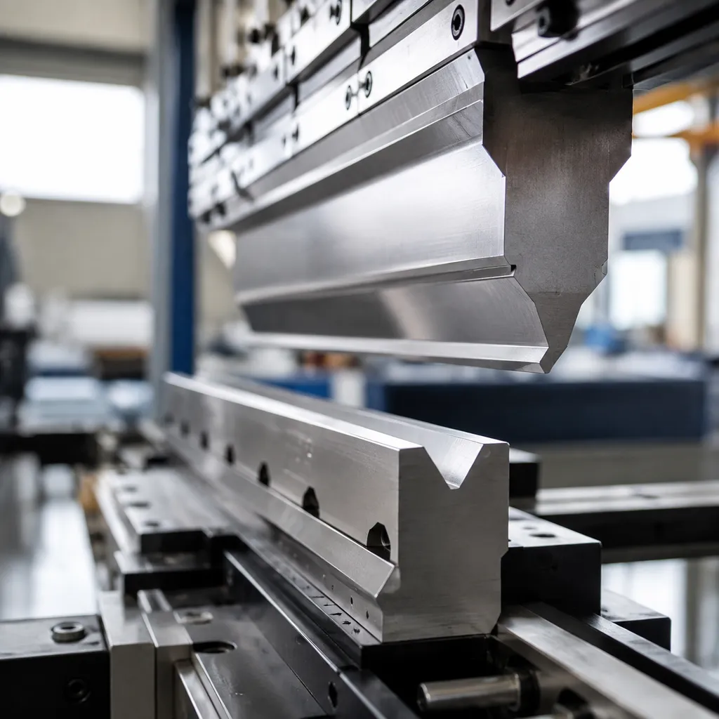
The 80% Tonnage Safety Rule
We always recommend applying an 80% safety margin to any bending operation. Running tooling at 100% of its rated die load capacity on a daily basis drastically speeds up metal fatigue.
- 3x Tool Life: Keeping your peak bending forces below 80% of the maximum limit can extend your tool life up to three times over standard duty cycles. Check out our detailed guide on extending your press brake v die lifespan to optimize your replacement cycles.
- Micro-Fatigue Prevention: Operating under peak capacity stops invisible micro-fatigue cracks from forming deep inside the hardened alloy core.
Point Loading vs. Uniform Load Distribution
A common mistake in sheet metal fabrication is ignoring how workpiece length alters force concentration. Rated limits (like 100 t/m or 1000 kN/m) assume the force is spread evenly across a full meter.
- Short-Length Hazards: Bending a 100 mm part concentrates the ram pressure over a tiny footprint.
- The Math Pitfall: Pushing 30 tons of force into a 100 mm part equals an effective load rate of 300 t/m. This instantly exceeds the max tonnage per meter of standard European style tooling, causing localized crushing or fracturing.
Identifying Catastrophic Die Failure Risks
When precision tooling exceeds its limits—or when operators accidentally bottom out an air-bending setup—structural failure follows a predictable, dangerous path:
| Failure Mode | Visual Signs | Root Cause |
|---|---|---|
| Shoulder Flattening | Shoulder radii lose roundness, showing flat spots or severe scoring. | Operating above rated limit or lack of lubrication. |
| V-Groove Expansion | The V-opening widens over time, causing inconsistent bend angles. | Overloading during air bending or bottoming thick plate. |
| Longitudinal Fracturing | Cracks run lengthwise along the bottom of the V-groove or tang. | Extreme point loading or sharp overload spikes. |
Upgrading to hardened precision European v-dies engineered from premium alloy steel ensures higher yield strength and significantly reduces the risk of sudden tool breakage under load.
European Style Press Brake Tooling Compatibility & Clamping
Standardized Tool Geometry & Sectionalization
Precision bending relies on tight mechanical tolerances and modular flexibility. The European design standard eliminates setup guesswork through uniform mounting dimensions and modular segment lengths:
- 13 mm Tang Standard: Built with a universal 13 mm tang featuring precision-machined safety grooves that engage automatically with safety pins to prevent tool dropping during loading.
- Modular Segment Sizing: Supplied in standard 835 mm continuous lengths, 415 mm half-lengths, and fully sectionalized sets that allow operators to combine segments quickly for complex box bending.
- Self-Centering Alignment: Micro-ground shoulders ensure the tool centers automatically along the ram axis, distributing force evenly and protecting against localized overload.
Quick-Clamping Adapters & Modern CNC Brake Integration
Modern high-tonnage CNC press brakes rely on rapid tool changes without sacrificing mechanical rigidity. Our European style press brake tooling integrates directly into standard manual clamps, push-button pneumatic holders, and fully automatic hydraulic clamping systems.
If your facility operates standard Promecam clamping or modern CNC machinery like Amada press brake tooling setups, our tools drop right into place with zero modification. We also engineer modified tang profiles to interface smoothly with power-clamping systems including WILA tooling adapters, Bystronic, and Trumpf receivers—giving you total cross-platform flexibility across your press brake fleet.
Quality Assurance for European Press Brake Die Rating
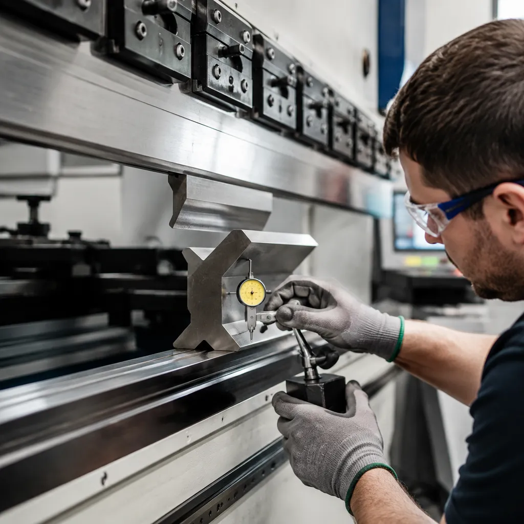
Material & Mechanical Testing Workflow
We do not leave raw material quality or die load capacity to chance. Every batch of tool steel undergoes strict testing before and after heat treatment:
- Spectrometric Chemical Analysis: We analyze raw steel samples using optical emission spectrometry to verify exact alloy composition (such as premium 42CrMo), ensuring zero material impurities or structural voids. Explore our detailed press brake tooling material guide to learn more about how alloy selection impacts tonnage capacity.
- Rockwell Hardness (HRC) Testing: We perform multi-point Rockwell hardness testing across deep induction-hardened zones. We confirm a surface hardness of HRC 55–60 along the die shoulders while preserving a ductile, shock-absorbing core.
Dimensional Verification & Traceability
High tonnage limits require micro-level precision. Uneven contact surfaces cause dangerous point loading that can shatter a die far below its rated capacity:
- CMM & Optical Projection Inspection: Using advanced Coordinate Measuring Machines (CMM) and optical profile projectors, we guarantee profile tolerances within ±0.01 mm and surface finish roughness below Ra 0.8 µm.
- Full Batch Traceability: Every manufactured tool is laser-etched with its nominal rating, segment length, and unique batch tracking number, backed by full material test certificates.
How to Select and Order Custom Rated European Tooling
Technical Parameters Required for Custom Engineering
To calculate the exact european press brake die rating and structural profile needed for your application, we evaluate five critical parameters:
| Parameter | Why It Matters |
|---|---|
| Sheet Thickness & Material | Dictates required V-opening and tonnage capacity based on tensile strength ($R_m$). |
| Minimum Flange Length | Determines shoulder radius positioning to prevent sheet slipping inside the V-die. |
| Open Height & Stroke Length | Prevents physical collision between upper punches, lower dies, and the ram. |
| Clamping Style | Ensures seamless fit with standard Promecam / Euro Pro quick-clamping or hydraulic holders. |
| Bending Angle & Radius | Controls die shoulder geometry and springback compensation. |
CAMT Engineering Support & Fast-Track Consultation
When off-the-shelf options fall short, our specialized custom tooling development process ensures you get maximum performance without risking tool failure. We take the guesswork out of complex press brake setups:
- Under 24-Hour Evaluation: Send us your part drawings, and our engineering team will evaluate tonnage requirements and feasibility within a single business day.
- 3D Simulation Analysis: We run finite element and 3D forming simulations to verify stress concentration points, preventing die shoulder degradation or body fracturing before manufacturing starts.
- Direct Factory Pricing: Eliminate distributor markups by working directly with us for high-grade 42CrMo precision ground tooling built to strict ISO tolerances.
Whether you need modified standard lengths or a fully bespoke profile, explore our engineered custom press brake tooling options built to match your specific press brake model and production demands.
Frequently Asked Questions
Converting kN/m to Tons per Foot
European style press brake tooling load capacity is typically expressed in kilonewtons per meter (kN/m) or metric tons per meter (t/m), whereas U.S. shops use short tons per foot (tons/ft).
To convert your European press brake die rating accurately:
| Unit Conversion | Conversion Multiplier | Practical Example |
|---|---|---|
| kN/m to Tons/ft | Multiply by 0.0307 | 1000 kN/m × 0.0307 = 30.7 tons/ft |
| t/m to Tons/ft | Multiply by 0.301 | 100 t/m × 0.301 = 30.1 tons/ft |
| Tons/ft to kN/m | Multiply by 32.55 | 30 tons/ft × 32.55 = 976.5 kN/m |
Exceeding Die Load Capacity
Exceeding the maximum tonnage rating of a European V-die risks permanent structural damage and severe safety hazards:
- Die Shoulder Flattening: Excessive point pressure deforms precision-ground shoulder radii, causing uneven bend angles.
- V-Groove Expansion: Yielding the core steel widens the opening, destroying die tolerances.
- Catastrophic Longitudinal Fracturing: Overloading causes brittle cracking along the body, sending high-velocity steel shrapnel across the shop floor.
- Ram and Bed Damage: Concentrating excessive load over short tool lengths can permanently indent your press brake ram.
For demanding heavy-duty applications, we always recommend verifying your setup against certified heavy-duty press brake dies to prevent unexpected structural overload.
42CrMo Steel vs. Standard Carbon Steel
We prefer 42CrMo chromium-molybdenum alloy steel over standard carbon steel for high-tonnage European tooling because of its superior mechanical properties:
- Core Toughness: Exceptional fatigue resistance absorbs high shock loads without fracturing.
- Deep Induction Hardening: Allows shoulder wear zones to reach HRC 55–60 while keeping the inner core flexible.
- High Yield Strength: Resists micro-fatigue cracking and structural deformation under continuous high-tonnage production cycles.
Air Bending vs. Bottoming Tonnage Limits
Understanding the operational difference between air bending force calculation and bottoming force is critical to keeping your Promecam style V die within safe limits:
- Air Bending: The sheet contacts only the die shoulders and punch tip. Tonnage requirements are low, usually using 20% to 30% of the die's structural load limit.
- Bottoming / Coining: The punch forces the sheet flat against the V-die walls. Force spikes 3x to 5x higher than air bending, easily exceeding the maximum tonnage safety margin and risking instant die shattering.
When forming sharp angles or narrow flanges, using dedicated acute punches under air bending parameters keeps force levels safely within rated limits.