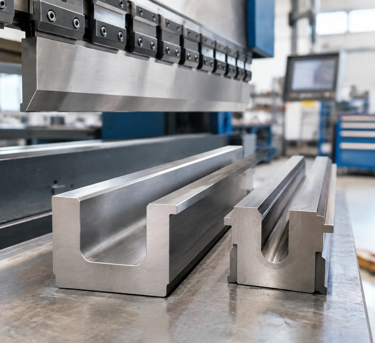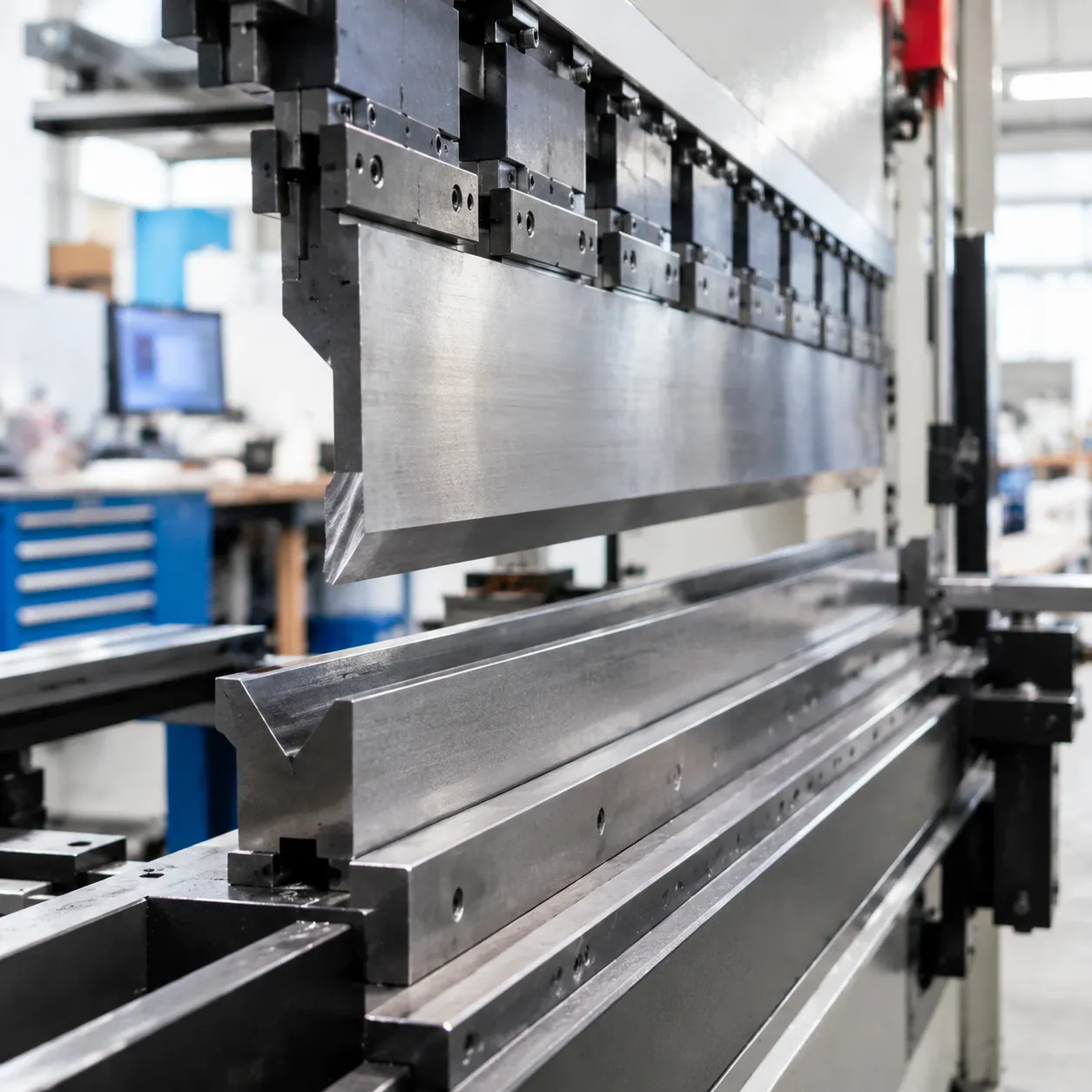
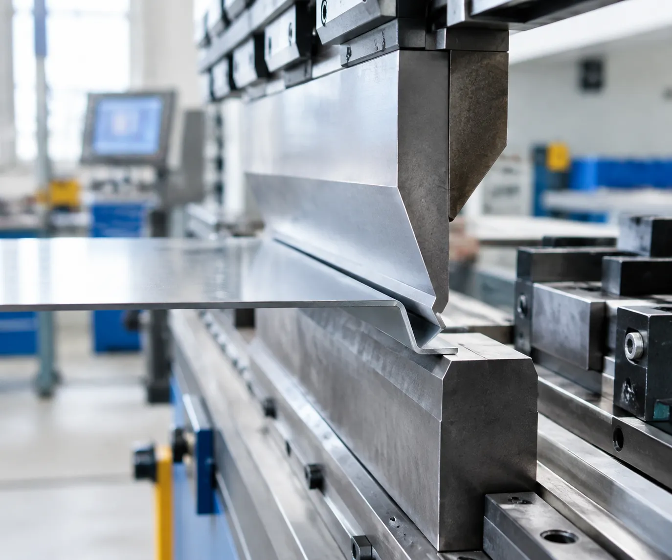
Formula details
Product Details
Overview
High-Performance Hemming Punches for Two-Stage Bending
Two-Stage Hemming Cycle Overview
Stage 1: Acute Pre-Bend (28°–30°)
Punch Tip
↓
Pre-form the flange to an acute angle
↓
V-Die
→
Stage 2: Final Hemming / Flattening
Punch Heel / Face
↓
Compress the pre-bent flange
↓
Closed / Dead Hem
↓
Spring / Hydraulic Flattening Die
How Two-Stage Hemming Punches Execute Acute Pre-Bending (28° to 30°)
The hemming process begins with an acute pre-bend. Our hemming punches are engineered with precision-ground tip angles ranging from 28° to 30°.
- Initial Penetration: The narrow tip drives the sheet into an acute lower die pocket, forming an overbent flange between 28° and 30°.
- Springback Overcoming: By pushing the bend past 30°, we compensate for inherent material springback in high-yield alloys.
- Flange Control: The sharp profile concentrates bending tonnage along a narrow radius line (R0.2 mm to R1.5 mm / R0.008 in to R0.060 in), setting a clean pivot point for the subsequent closing stage.
Flattening and Closing Mechanisms by Hem Type
Once the acute pre-bend is complete, the workpiece shifts either horizontally onto a flat die surface or vertically within a dynamic lower tool. Our punches accommodate three primary hem variations:
| Hem Type | Target Gap / Geometry | Primary Application | Tonnage Requirement (Mild Steel) |
|---|---|---|---|
| Dead Hem (Flat) | 0 mm (fully crushed, zero clearance) | Safety edges, double-thickness structural stiffeners | 500–900 kN/m (35–60 Tons/ft) |
| Open Hem (C-Type) | 0.5–2.0 mm (0.020–0.080 in) uniform gap | Powder coating drainage, secondary panel insertions | 200–350 kN/m (14–24 Tons/ft) |
| Teardrop Hem | Smooth curved loop radius | Aluminum, high-strength steels prone to cracking | 150–300 kN/m (10–20 Tons/ft) |
- Dead Hems: The flat front face or dedicated flattening heel of our punch drives down with high vertical tonnage to collapse the pre-bent flange flat against the parent sheet.
- Open Hems: Integrated stroke limiters or CNC axis depth stops prevent full closure, maintaining an exact gap.
- Teardrop Hems: The punch radius and lower die pocket geometry curl the outer edge without creasing the apex, preserving material grain integrity.
Key Production Advantages
- Eliminating Sheet Slippage: Engineered punch contact angles trap the sheet securely during the transition from acute forming to flattening, preventing lateral drift.
- Cycle Time Reduction: Combining pre-bending and flattening in one tool station cuts part cycle times by up to 40% compared to separate two-die operations.
- Preventing Back-Gauge Collision: Slim relief angles and optimized punch-body geometry provide clearance for back-gauge fingers during high-speed return strokes.
Seamless Integration with Lower Hemming Dies
Our hemming punches pair directly with standard press brake tables as well as advanced dynamic lower die systems:
- Spring-Loaded Dutch Dies: Utilize mechanical die springs to hold the V-opening open for Stage 1, then compress under higher tonnage for Stage 2 flat crushing.
- Pneumatic Hemming Benches: Air-actuated lower die blocks shift between an open V-groove and an elevated flat surface via foot switch or CNC automation.
- Hydraulic 2-Stage Lower Tools: High-tonnage hydraulic pistons support the lower flattening plate, enabling heavy-gauge hemming (up to 3.0 mm / 0.120 in mild steel) without manual tool adjustments.
Clamping Styles and Press Brake Machine Compatibility
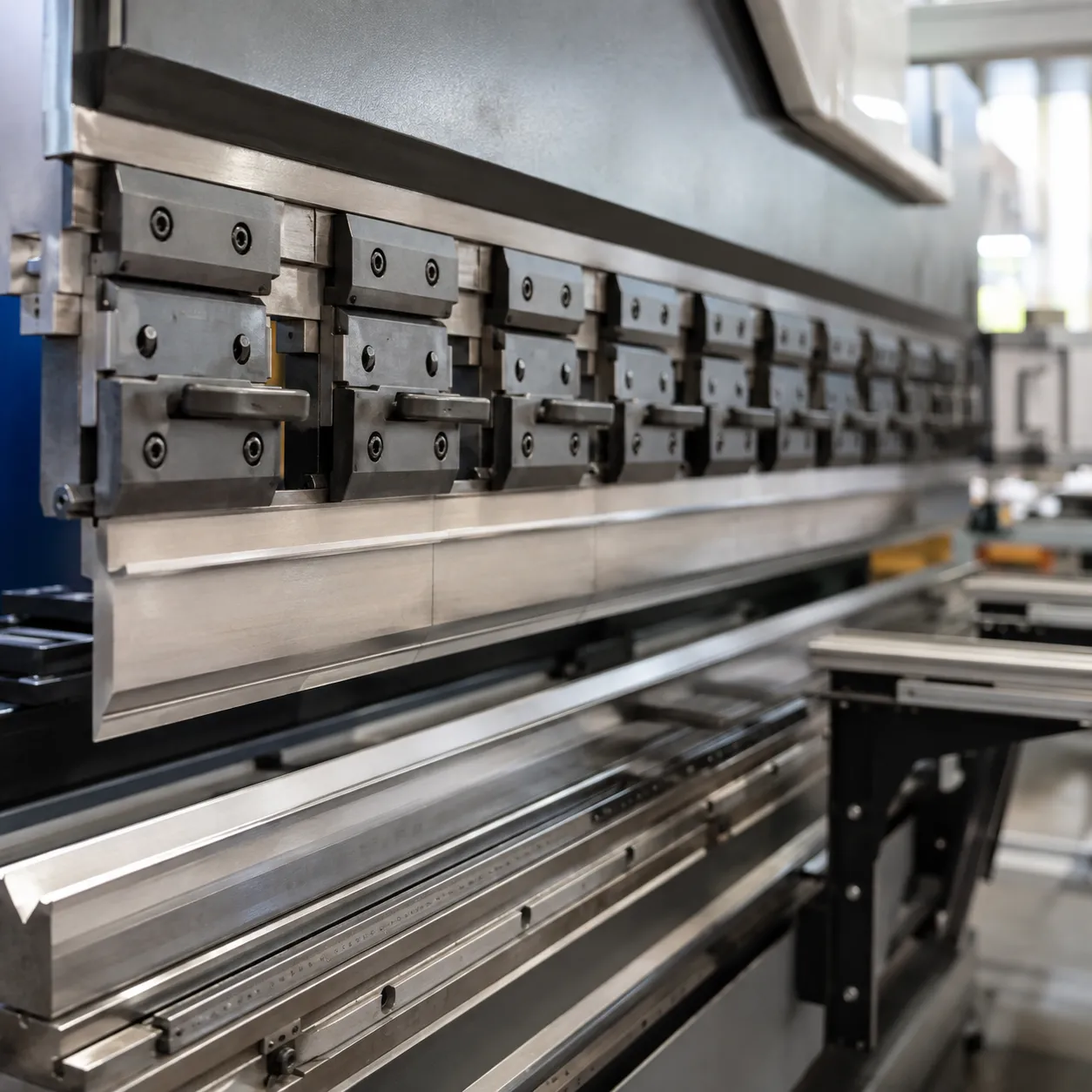
We manufacture our hemming punches to integrate directly with all primary machine clamping configurations, ensuring precise centerline alignment, fast changeovers, and zero tool drift under high-tonnage flattening loads.
Standard Clamping Systems We Support
- European Precision Style (Amada-Promecam): Configured with standard tang dimensions and safety click grooves or manual pins. These punches lock securely into European-style mechanical or hydraulic tool holders, maintaining rigid vertical repeatability during both the acute pre-bend and final hem closure.
- Wila & Trumpf New Standard: Precision-ground with integrated Safety-Click mechanism pins for instant vertical loading and self-seating alignment. This setup eliminates side-loading issues and significantly reduces setup times on automated CNC press brakes.
- American Traditional Hook Tangs: Machined with standard 0.500 in (12.7 mm) tangs, safety tang notches, and hook profiles. For shops running legacy or modern American mechanical clamps, explore our American style press brake tooling to match your exact beam profile.
- Bystronic & Custom Machine Adapters: Built with dedicated Bystronic-Beyeler upper tang configurations or intermediate clamp adapters, ensuring seamless integration on specialized multi-axis European press brakes without sacrificing open height.
| Clamping Style | Tang Dimension | Retention Method | Loading Method | Primary Compatibility |
|---|---|---|---|---|
| European Precision | 12.7 mm / 20 mm step | Safety groove / ball lock | Horizontal / Slide-in | Amada, Promecam, Durma, Accurpress |
| New Standard | 20 mm with Safety-Click | Push-button pin lock | Direct Vertical Drop / Click-in | Wila, Trumpf, Prima Power |
| American Standard | 0.500 in (12.7 mm) | Clamping bar / Hook tang | Horizontal slide | Cincinnati, Standard Industrial, Pacific |
| Bystronic-Beyeler | Dedicated tang profile | Hydraulic wedge / mechanical | Vertical / Horizontal | Bystronic, Beyeler, LVD |
To ensure exact fitment with your lower die set and machine daylight limits, check our complete press brake hemming tools guide before configuring custom punch heights or modified tang adapters.
Engineering Profiles and Hemming Punch Geometries
Acute 28° to 30° Narrow-Tip Punches for Tight Pre-Bends
Achieving a clean closed hem begins with an overbent acute angle. We design our 28° to 30° narrow-tip punches with slim profiles to overbend sheet metal sufficiently, compensating for natural material springback before the part moves to the flattening stage.
Overbend Capability: Overcomes yield strength resistance in high-tensile alloys.
Narrow Tip Relief: Provides side clearance to avoid premature contact with adjacent bends.
Dual-Action Combination Punches with Integrated Flattening Heels
To maximize press brake efficiency, our combination hemming punches feature an acute bending nose paired with a flat horizontal shoulder or rear heel.
Single-Setup Operation: The operator forms the 30° acute bend at the punch tip and completes the hem closure against the integrated flattening flat in the same stroke cycle.
Reduced Setup Time: Eliminates the need for secondary tool stations or separate machine transfers.
Relief Profiles for Complex Flanges
Standard straight punches often collide with return bends on deep boxes and specialized profiles. To maintain clearance on complex geometries, we manufacture relief-profile hemming tooling:
Gooseneck Relief: When closing hems on deep U-channels or inner flanges, our heavy-duty gooseneck punches provide the throat depth necessary to clear pre-formed standing legs.
Offset Geometry: For tight channel returns and narrow edge hems, engineered offset punches shift the load line while preventing tooling deflection.
Punch Tip Radius Variations and Crack Prevention
Matching the punch tip radius to your material type and gauge is essential for structural integrity along the bend seam:
| Tip Radius | Typical Sheet Thickness | Recommended Materials | Primary Function |
|---|---|---|---|
| R0.2 mm – R0.6 mm (0.008" – 0.024") | 0.5 mm – 1.0 mm (0.020" – 0.039") | Mild steel, thin cold-rolled sheets | Tight acute pre-bending without slippage |
| R0.8 mm – R1.0 mm (0.031" – 0.039") | 1.0 mm – 1.5 mm (0.039" – 0.059") | Stainless steel (304, 316) | Prevents grain separation and fracture |
| R1.2 mm – R1.5 mm (0.047" – 0.059") | 1.5 mm – 3.0 mm (0.059" – 0.118") | Aluminum alloys (5052, 6061) | Eliminates surface micro-cracking during teardrop hems |
Tooling Metallurgy and Technical Specifications
Premium Tool Steels & Heat Treatment
- Base Alloy Steels: We forge every 42CrMo press brake punch using high-grade 42CrMo (AISI 4140 / 1.7225) alloy tool steel, delivering exceptional fatigue strength and resistance to heavy shock loads.
- Surface Hardening: Critical contact points—including the acute tip and flattening face—undergo deep induction or laser hardening reaching 52–58 HRC, preventing friction wear and groove formation over extended runs.
- Core Toughness: The structural core is kept tempered at 28–32 HRC to absorb dynamic shock and prevent brittle cracking under sudden flattening loads.
- Precision CNC Grinding: All working profiles, tangs, and reference surfaces are CNC ground to a tolerance of ±0.01 mm (±0.0004 in), ensuring 100% interchangeability across segmented sets and complete compatibility with our precision press brake punches.
Engineering Specifications
| Specification Parameter | Standard Range / Value |
|---|---|
| Base Material | 42CrMo / 4140 / 1.7225 Forged Tool Steel |
| Wear Zone Hardness | 52–58 HRC (Laser / Induction Hardened) |
| Core Hardness | 28–32 HRC (Through-Hardened & Tempered) |
| Grinding Tolerance | ±0.01 mm / ±0.0004 in |
| Standard Working Heights | 66.6 mm, 120 mm, 150 mm, 175 mm, 200 mm+ (2.62" to 7.87"+) |
| Maximum Tonnage Rating | Up to 1000 kN/m (100 Tons/ft) based on tool geometry |
Standard Tool Lengths and Sectionalized Hemming Sets
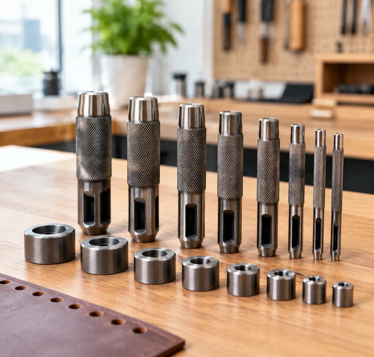
We manufacture our hemming punches in both continuous solid lengths and precision-cut sectionalized sets to match diverse press brake bed configurations and part geometries.
Solid Tooling Lengths
For long-run production, continuous panel processing, and full bed-length bending, solid tools deliver maximum rigidity and eliminate segment seam marks:
- 835 mm (32.87 in): Standard full-length punch for high-tonnage straight runs.
- 500 mm (19.68 in): Mid-length section optimized for standard machine bed setups and easy single-operator handling.
- 415 mm (16.34 in): Half-length segment for smaller press brakes or split-bed operations.
Standard 835 mm Segmented Sets
Our standard 835 mm segmented punch sets allow operators to configure any required bending length in 5 mm increments within seconds. Each set includes:
| Segment Length (mm) | Quantity per Set | Primary Function |
|---|---|---|
| 100 mm (Left Horn) | 1 | Clearance for pre-bent side flanges |
| 100 mm (Right Horn) | 1 | Clearance for pre-bent side flanges |
| 100 mm (Standard) | 1 | Straight run buildup |
| 50 mm | 1 | Incremental width adjustment |
| 40 mm / 20 mm / 15 mm / 10 mm | 1 each | Fine length tuning |
| 370 mm / 200 mm | 1–2 | Main body section filling |
The left and right horn ear pieces feature precision-milled relief cutouts that provide clearance for pre-formed vertical side flanges during the acute pre-bend and closing stages.
[100 Horn L] + [370] + [100] + [50] + [40] + [20] + [15] + [10] + [100 Horn R]
|<--------------------------- Total Length: 835 mm --------------------------->|
Custom Sectionalized Configurations for Enclosures
Fabricating deep four-sided enclosures, trays, and electrical boxes requires specialized tool clearance. When standard profiles interfere with upright flanges, we supply custom-segmented press brake hemming punch systems paired with high-performance hemming dies. These custom sectionalized configurations prevent sheet distortion and allow full four-sided hem closing without tool collision.
Sheet Metal Capacities and Hem Formation Guidelines
Forming clean, crack-free hems requires balancing punch geometries, sheet metallurgy, and tonnage distribution. We engineer our hemming punches to handle everything from light-gauge cosmetic skins to heavy structural seams across diverse sheet metal grades.
Material Capacities and Forming Parameters
- Mild Steel (0.5 mm to 2.5 mm / 0.020" to 0.098"): Standard cold-rolled carbon steel forms reliably with an acute pre-bend of 30°. Typical flattening force requires roughly 40 to 90 kN/m (4.5 to 10 Tons/ft) depending on thickness.
- Stainless Steel (0.5 mm to 1.5 mm / 0.020" to 0.059"): High tensile strength and work-hardening require sharp 28° acute pre-bends to compensate for elastic recovery. Review our press brake die angles guide for springback selection to match the pre-bend profile to your specific material yield. For high-demand stainless steel processing, flattening tonnages will run 50% to 100% higher than mild steel.
- Aluminum Alloys (0.8 mm to 3.0 mm / 0.032" to 0.118"): Softer alloys (like 3003-H14) hem easily, while tempered series (such as 5052-H32 and 6061-T4) crack under dead hemming. We recommend larger punch tip radii (R0.8 mm to R1.5 mm) paired with teardrop closing stops.
Hem Type Selection Matrix
| Hem Profile | Target Gap | Thickness Range | Relative Tonnage | Best Used For |
|---|---|---|---|---|
| Flat Crushed (Dead Hem) | 0 mm (Zero Clearance) | 0.5 – 1.5 mm (0.020" – 0.059") | High (60–120 kN/m) | Safe handling edges, maximum edge stiffness, enclosure lips |
| Open Hem (Air Hem) | 0.5 to 2.0 mm (0.020" to 0.080") | 0.8 – 2.5 mm (0.032" – 0.098") | Medium (25–50 kN/m) | Sliding joints, panel interlocks, wire-edge insertions |
| Teardrop Hem | Radius-formed loop | 0.8 – 3.0 mm (0.032" – 0.118") | Low (15–35 kN/m) | Crack-prone aluminum, heavy galvanized sheets, thick panels |
Practical Hemming Rules for the Shop Floor
- Pre-Bend Acute Depth: Ensure your acute pre-bend punch creates a consistent 28 °–30 ° angle along the full bend line. Under-bending in stage one causes the sheet to slide out during stage two.
- Minimum Return Flange Length: Maintain a minimum return flange of b_{min} ge 4 × sheet thickness + punch tip radius to keep the sheet seated squarely during closure.
- Grain Direction Orientation: When working near maximum thickness limits, always form the hem perpendicular to the sheet metal grain direction to eliminate seam splitting during final flattening.
Industrial Applications for Sheet Metal Hemming Punches
Electrical Enclosures, Server Racks, and Control Cabinets
- Wire Protection: Eliminates sharp burrs on interior frame cutouts, cable access paths, and door frames, preventing wiring insulation damage during installation.
- Perimeter Stiffness: Hemmed returns provide high rigidity against panel bowing in thin mild steel (0.8 mm to 1.5 mm / 0.031" to 0.059") without welding extra stiffener ribs.
- Gasket Sealing Surfaces: Creates flat, smooth contact planes necessary for consistent compression on IP-rated and NEMA-rated enclosure door gaskets.
HVAC Ductwork, Architectural Panels, and Commercial Doors
- Acoustic & Pressure Sealing: Forms tight dead hems and standing seams on galvanized duct sections to eliminate air leakage and vibration hum.
- Architectural Cassettes: Produces uniform, ripple-free borders on aluminum and steel cladding panels with crisp outer lines.
- Commercial Metal Doors: Rapidly closes lock-seams and perimeter edges on hollow metal doors, maintaining parallel alignment across full bed lengths.
Medical Equipment and Cleanroom Panels
- Safe-Edge Compliance: Medical carts, diagnostic enclosures, and laboratory consoles require 100% burr-free edges to protect medical personnel and prevent tearing cleanroom gloves.
- Sanitary Construction: Tightly crushed hems eliminate open crevices where moisture, cleaning chemicals, or contaminants can settle, simplifying wipe-down and sterilization routines.
Appliance Casings and Consumer Metal Products
- Exterior Aesthetic Hems: Washing machine housings, ranges, and commercial refrigeration units utilize our hemming punch and die systems for clean, scratch-free border hems on stainless and pre-painted sheet.
- Retail & Commercial Fixtures: Widely applied in high-volume shelving, storage lockers, and metal furniture applications where touchpoints require complete edge smoothing and long-term durability.
Frequently Asked Questions About Hemming Punches
What is the primary difference between standard acute punches and dedicated hemming punches?
A standard acute punch is designed strictly for air bending angles between 28° and 30°. Dedicated hemming punches feature reinforced tool shanks, modified tip profiles, and relief geometries tailored to survive the heavy downward compression of the flattening phase. When paired with two-stage lower dies, a dedicated press brake hemming punch guides the pre-bent sheet directly into the flattening position without side deflection, tool rubbing, or premature tip wear.
How do I calculate the required tonnage for the final flattening stage?
Flattening a pre-bent hem requires significantly more pressure than the initial acute air bend—frequently 3 to 5 times higher depending on whether you are forming a dead hem or an open hem.
| Sheet Material | Thickness Range | Approx. Pre-Bend Tonnage | Approx. Flattening Tonnage (Dead Hem) |
|---|---|---|---|
| Mild Steel | 1.0 mm (0.039 in) | 80–100 kN/m (2.7–3.4 T/ft) | 350–500 kN/m (12–17 T/ft) |
| Mild Steel | 1.5 mm (0.059 in) | 120–150 kN/m (4.1–5.1 T/ft) | 600–800 kN/m (20–27 T/ft) |
| Stainless Steel | 1.0 mm (0.039 in) | 130–160 kN/m (4.4–5.4 T/ft) | 550–750 kN/m (19–25 T/ft) |
| Aluminum (5052-H32) | 1.5 mm (0.059 in) | 70–90 kN/m (2.4–3.1 T/ft) | 250–350 kN/m (8.5–12 T/ft) |
Always calculate the maximum working load against your machine frame and tooling limits using our European press brake die rating guide for tonnage safety to prevent overloading the tool tip or receiver.
How do I prevent cracking when hemming high-tensile stainless steel or aluminum?
Cracking along the bend line during hem closure usually stems from excessive strain hardening, sharp punch tips, or bending parallel to the grain. We recommend the following parameters to eliminate edge fractures:
Switch from dead hems to teardrop or open hems: Trapping a small radius inside the fold relieves the extreme inner-surface tension.
Increase punch tip radius: Replace sharp R0.2 mm (0.008 in) tips with R0.6 mm to R1.0 mm (0.024 to 0.039 in) profiles to enlarge the initial inside bend radius.
Orient across the rolling grain: Always position the bend line perpendicular (90°) or at 45° to the sheet metal grain direction.
Review material-specific tool setups: Consult our press brake die selection for aluminum guide for complete bend deduction and radius recommendations across various alloy tempers.
Can combination hemming punches perform both bending stages in a single machine setup?
Yes. When paired with a two-stage spring-loaded or pneumatic lower hemming die, a combination hemming punch executes both actions seamlessly. The press brake ram cycles the acute punch into the die opening for the 28°–30° pre-bend, the operator advances the sheet to the flat die shoulder, and the second stroke compresses the hem flat without changing tooling or altering the mechanical setup.
Which punch tip radius is ideal for thin-gauge sheet metal hemming?
For ultra-thin sheet metal between 0.5 mm and 1.0 mm (0.020 in to 0.040 in), an R0.2 mm to R0.4 mm punch tip radius provides the tightest pre-bend angle necessary for a crisp dead hem. For material thicknesses between 1.2 mm and 2.0 mm (0.048 in to 0.078 in), step up to an R0.6 mm or R0.8 mm tip radius to distribute compressive loads evenly and prevent the punch from scoring the inner bend line.