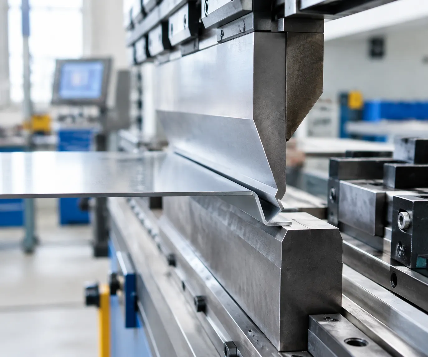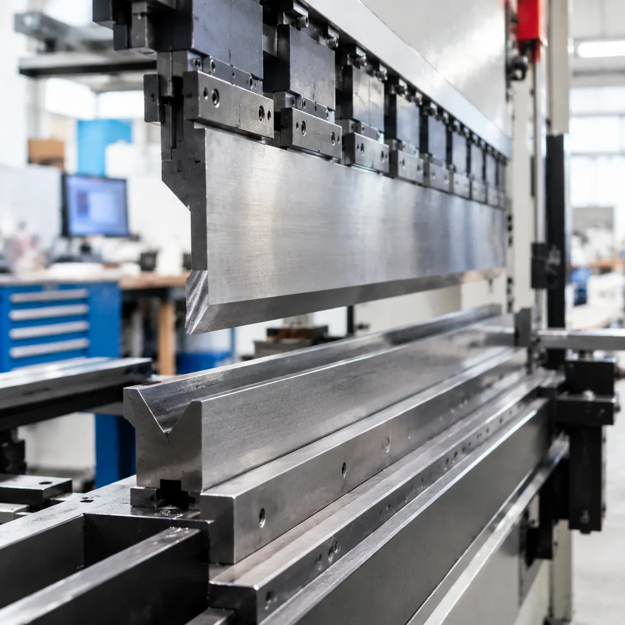
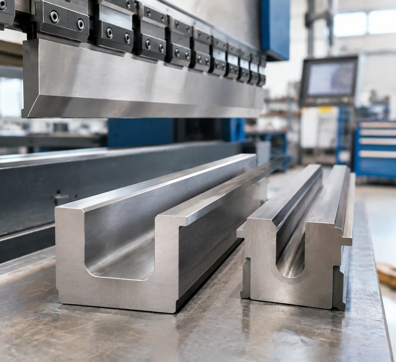
Formula details
Product Details
Overview
U-Dies for Press Brakes: Overview & Forming Mechanics
Forming narrow, parallel-flange channels with standard V-dies typically requires two separate strokes, part flipping, and precise backgauge realignment. U-dies for press brakes—also referred to as press brake channel dies or single-hit U-bend tooling—form both 90-degree bends simultaneously in a single machine cycle.
Single-Stroke Channel Forming vs. Multi-Step V-Die Bending
Using a dedicated U bending die fundamentally transforms your shop-floor throughput by streamlining sheet metal channel bending:
- Cycle Time Reduction: Cuts cycle times by 50% or more by completing the profile in one downstroke.
- Flange Parallelism: Fixed die sidewalls and precision-matched punch profiles ensure that both vertical legs remain strictly parallel without flange flare.
- Elimination of Tolerance Stacking: Forming both bends simultaneously eliminates backgauge positioning variance between the first and second hit.
| Feature / Metric | Single-Hit U-Die Tooling | Standard V-Die Bending |
|---|---|---|
| Machine Strokes Required | 1 stroke | 2 sequential strokes + part flip |
| Profile Consistency | Tool-locked geometry (±0.01 mm to ±0.02 mm) | Operator- & backgauge-dependent |
| Cycle Efficiency | Maximum output for high-volume channels | Slower, multi-stage handling |
| Part Scratch Risk | Controlled with polished shoulder radii | High due to multiple sliding contacts |
Scratch-Free Surface Options for Sensitive Materials
Forming pre-painted, galvanized, or mirror-finish stainless steel sheets requires strict surface protection to prevent galling, tool marking, and cosmetic defects.
- Precision-Ground Shoulder Radii: Highly polished, CNC-ground entry radii reduce frictional drag as the sheet draws into the die cavity.
- Protective Polyurethane Film Channels: Die shoulders designed to support protective anti-marking film prevent direct metal-to-metal friction during bottoming.
- Optimized Die Clearances: Engineered entry geometry reduces contact pressure peaks, keeping cosmetic surfaces pristine without post-finishing operations.
Technical Specifications & Tool Steel Engineering for U-Dies
Tool durability starts with proper metallurgy, uniform core toughness, and deep localized hardening on critical wear shoulders.
Tool Steel Substrate Selection
- 42CrMo Alloy Steel: Our primary choice for heavy-duty press brake channel dies. High tensile strength and fatigue resistance prevent tool fracture under concentrated loads.
- C45 Carbon Steel: A dependable, economical grade for light-gauge channel bending and medium-duty forming runs.
- Cr12MoV / D2 Tool Steel: High-carbon, high-chromium alloy offering maximum abrasive resistance for continuous production in demanding materials.
Thermal Processing & Hardness Distribution
Channel forming concentrates significant abrasive friction on die shoulders and bottom radii. We balance tool flexibility and wear life through multi-stage heat treatment:
Core Toughness: Tempered to HRC 45–48 to absorb deflection forces and prevent catastrophic breakage under high tonnage.
Working Surfaces: Shoulder radii and contact flats are induction or laser hardened to HRC 52–60, ensuring our press brake die sets for high-strength steel maintain dimensional integrity across thousands of cycles without galling.
| Technical Parameter | Standard Specification |
|---|---|
| Material Grades | 42CrMo (Standard), C45, Cr12MoV / D2 |
| Core Hardness | HRC 45–48 |
| Wear Zone Hardness | HRC 52–60 (Induction / Laser Hardened) |
| Height & Parallelism Tolerance | ±0.01 mm to ±0.02 mm precision-ground |
| Standard Lengths | 835 mm, 415 mm, continuous lengths to machine bed size |
| Segmented Configurations | Multi-piece sets (100, 50, 40, 20 mm, and ear horns) |
Precision Tolerances and Segmented Tool Sets
Every 42CrMo press brake die is CNC finish-ground across critical reference surfaces. Tight working height parallelism within ±0.01 mm to ±0.02 mm ensures seamless tool alignment when combining standard solid lengths (835 mm, 415 mm) or staging segmented sets for enclosed box and channel bending.
Press Brake U-Die Profile Configurations & Tooling Types
Standard One-Hit U-Dies for Symmetrical Channels
Our single-hit channel forming die profiles are built to deliver balanced, parallel 90° flanges in a single machine stroke:
Forming Action: Simultaneous dual-radius wipe and bottom form.
Flange Symmetry: Balanced side-wall pressure prevents channel skewing.
Production Advantage: Eliminates part repositioning required by standard multi-step V-bending setups.
Deep-Channel Relief U-Dies for Tall Vertical Flanges
Standard dies collide with deep upright legs. We engineer specialized deep channel press brake dies with relieved side profiles:
Clearance Relief Pockets: Machined side-wall recesses prevent interference with tall vertical flanges during the downstroke.
Complex Profiles: Handles return bends, pre-formed standing hems, and narrow C-channel geometry.
Rigidity Control: Reinforced outer tool bodies sustain high side-thrust forces during deep draws.
Modular & Adjustable-Width U-Channel Tooling
For job shops processing variable sheet thicknesses without swapping full tool bodies, our modular systems offer flexible setup:
Interchangeable Inserts: Swap center spacers and shoulder radii inserts within a heavy-duty master die holder.
Variable Web Widths: Adjust channel base dimensions quickly to process different material gauges on the same brake.
Explore our full range of metal forming press brake dies for sale to configure modular bases for custom production runs.
Spring-Loaded & Ejector-Assisted U-Dies
Bottoming a tight U-channel causes high friction between the part and the die walls:
Mechanical & Urethane Ejectors: Built-in bottom ejector pads actively push the finished channel out of the die cavity on the return stroke.
Sticking Prevention: Eliminates manual prying, preventing flange distortion and surface scratching on finished parts.
Automation Ready: Consistent part ejection supports robotic press brake cells and automated part transfer.
| Tooling Type | Best Application | Key Advantage | Typical Thickness Range |
|---|---|---|---|
| One-Hit Solid U-Die | High-volume standard channels | Maximum rigidity and tightest profile repeatability | 0.8 mm – 6.0 mm |
| Deep-Relief U-Die | Tall return flanges & C-sections | Prevents side-wall collisions on deep profiles | 1.0 mm – 4.0 mm |
| Adjustable Modular Die | Variable gauge job-shop bending | Multi-thickness flexibility with lower tooling costs | 1.0 mm – 8.0 mm |
| Ejector-Assisted U-Die | High-precision scratch-free channels | Fast, non-stick part release for automated lines | 0.5 mm – 3.0 mm |
These channel configurations integrate directly with our precision-ground press brake bottom dies lineup to handle demanding industrial forming requirements without tool deflection.
Press Brake Clamping Systems & U-Die Compatibility
We engineer our U-dies for press brakes to mount directly into your machine's bed without requiring secondary adapters or custom shimming. We precision-grind every base tang to ensure accurate centerline positioning, rigid seating, and immediate compatibility across major global machine interfaces:
- Amada-Promecam European Style: Machined with standard 12.7 mm base tangs, fully compatible with traditional mechanical clamp plates, quick-clamping levers, and European-style lower holders.
- Trumpf & Wila New Standard: Configured with hardened safety pins and auto-seating geometry for hydraulic and pneumatic tool holders on Wila compatible tooling systems.
- American Precision Standard: Precision-machined with standard 0.500-inch tang profiles to fit traditional North American lower tool holders and standard slotted bed rails.
- Bystronic, LVD, and Beyeler Tables: Custom-ground lower bases engineered for direct table mounting, specialized single-shoulder locations, or bolt-down slot configurations. Check our press brake die size chart and dimensions guide for exact profile and tang specifications.
Engineering Selection Guidelines & Bending Dynamics for U-Dies
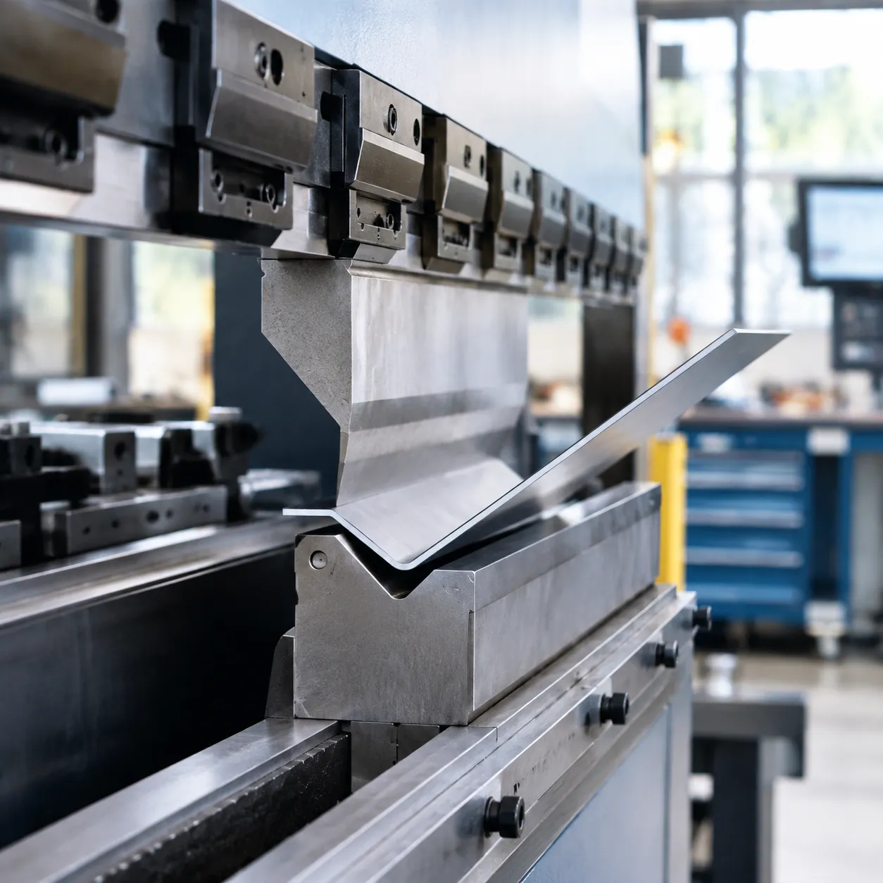
Forming channels in a single hit completely changes the bending dynamics compared to standard single-bend tooling. When using U-dies for press brakes, you are executing two simultaneous bends under high friction. Getting clean, parallel vertical legs without over-tonnage or side-wall galling requires exact calculations.
Tonnage Calculation & Bottoming Multipliers
A single-stroke channel forming die requires significantly more force than standard air bending. Because the punch forces the sheet down between two die shoulders while coining or bottoming the base, tonnage spikes rapidly:
- Tonnage Multiplier: Plan for 2.5× to 4× the tonnage of a standard single V-die bend of identical thickness and length.
- Punch-to-Die Contact: As the sheet enters the die cavity, sliding friction against both side walls increases resistance before reaching the bottom.
- Bottom Radius Sizing: Bottoming the part flat requires sufficient machine capacity to prevent hydraulic stall or tooling deformation.
Springback Compensation for 90° Parallel Flanges
Sheet metal naturally springs outward once released from the die cavity. To achieve true 90° parallel sidewalls on your finished U-profile, we engineer negative relief angles directly into the vertical die walls.
Review our press brake die angles guide for springback selection to determine the exact relief profile needed for your specific metal grade:
- 88° Relief Walls: Standard for mild steel (CR4, A36) to overcome 1° to 2° of elastic recovery per side.
- 86° Relief Walls: Optimized for structural grades, high-strength steels, and cold-rolled alloys.
- 84° Relief Walls: Required for 300-series stainless steels and spring-prone tempered materials.
Clearance Ratios & Punch Radius Matching
To prevent binding, part jamming, and severe side-wall burnishing, we maintain strict clearance rules when engineering custom U-bend tooling:
- Die Cavity Width ($W_d$): Calculated as Punch Width ($W_p$) + 2 × Material Thickness (T) + Clearance (C).
- Clearance Allowance ($C$): Typically set between 5% to 10% of material thickness per side to accommodate material thickness variations.
- Punch Nose Radius ($R_p$): Must match the desired inside radius ($R_i$) of the channel. Punch radii that are too sharp create heavy stress concentrations and increase tonnage requirements.
Material-Specific Forming Parameters
Different alloys behave uniquely inside press brake channel dies. Refer to our press brake die selection for aluminum guide when forming softer alloys to avoid galling and outer radius cracking.
| Material Type | Typical Springback | Die Side Angle | Clearance per Side (% of T) | Tonnage Factor (vs. Single V Air Bend) |
|---|---|---|---|---|
| Mild Steel (e.g., A36, 1018) | 1.5° – 2.0° | 88° | +5% to +8% | 2.5× – 3.0× |
| Stainless Steel (304 / 316) | 3.0° – 4.5° | 84° – 86° | +8% to +12% | 3.5× – 4.5× |
| Aluminum (5052-H32 / 6061-T6) | 2.0° – 3.5° | 86° – 87° | +6% to +10% | 2.0× – 2.5× |
Industrial Applications for Press Brake U-Dies
Electrical Enclosure Tracks, Chassis & DIN Rail Brackets
- Electronic Chassis Channels: Delivers tight, consistent web widths for server racks, power distribution enclosures, and industrial control cabinets.
- DIN Rail Mounting Brackets: Forms small-profile symmetrical tracks without side-wall distortion, ensuring clip-on industrial components fit properly.
- Scratch-Free Enclosure Shells: Compared to repositioning parts across a standard precision press brake V-die, single-hit U-channel forming eliminates repeated sliding marks and surface scratching on pre-painted, galvanized, and stainless steel panels.
Logistics Cable Trays, Strut Channels & Unistrut Profiles
- Cable Management Systems: Handles long-run bending of standard cable trays, wire management runs, and protective conduits across continuous or segmented tool lengths.
- Strut Channels & Frame Profiles: Produces rigid C-channels and slotted unistrut-style profiles used in commercial electrical grids and warehouse racking.
- True Flange Parallelism: Prevents side-flange flaring or web crowning over extended tool sections, ensuring modular hardware and connectors slide into the profile smoothly.
Heavy Equipment Structural C/U Channels & Crossmembers
- Vehicle Frame Crossmembers: Built to withstand the high bottoming tonnage required for forming heavy structural channels in truck trailers, agricultural equipment, and rail chassis.
- High-Strength Steel Bending: Deep-hardened tool shoulders handle high-yield steels up to 6 mm and thicker, compensating for material springback in high-stress structural profiles.
- Heavy-Duty Wear Resistance: Precision-machined from hardened 42CrMo alloy steel to eliminate shoulder galling and premature tool wear under heavy industrial forming loads.
Custom U-Die Engineering & Manufacturing Workflow
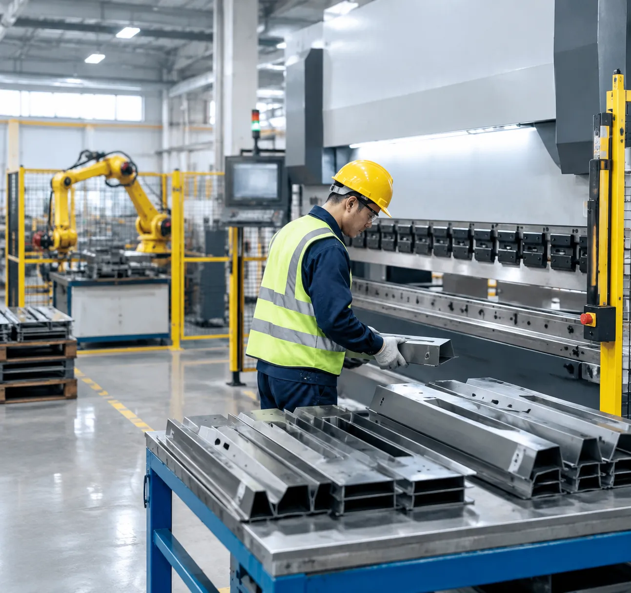
When standard tooling profiles cannot clear complex return flanges or meet tight channel tolerances, we engineer custom U-dies for press brakes tailored directly to your sheet metal specifications and machine tonnage limits. Our in-house design and production workflow ensures every custom U-bend tooling set delivers repeatable, production-ready accuracy straight out of the crate.
1. CAD Evaluation & DXF/STEP Analysis
We start by evaluating your 2D DXF profiles and 3D STEP models. Our engineers analyze the critical channel dimensions:
Material thickness ($T$) and internal bend radius ($R$)
Flange height to bottom web ratios
Part side-clearance requirements to prevent tool interference
2. 3D Stroke Simulation & Springback Compensation
Forming symmetrical U-channels in a single stroke creates significant side friction and material springback. We simulate the entire press brake stroke in 3D CAD to verify punch penetration depth and backgauge clearances. Using material-specific elongation and yield strength data, we design modified side-wall relief angles (such as 88° or 86°) to ensure final 90° parallel flanges after bottoming.
3. Multi-Axis Precision CNC Machining & Grinding
We machine all custom channel forming dies from certified high-strength alloy billets, primarily 42CrMo (42CrMo4).
Rough and finish milling executed on multi-axis CNC machining centers
Precision surface grinding to maintain critical working heights and centerline parallelism within ±0.01 mm to ±0.02 mm
Follow our in-depth breakdown of standard fabrication steps in our step-by-step die manufacturing guide
4. Deep Induction Hardening on High-Wear Zones
To withstand heavy bottoming and continuous sliding friction during sheet metal channel bending, our tooling undergoes specialized multi-stage thermal processing:
Core Toughness: Quenched and tempered to HRC 45–48 to prevent body cracking under high tonnage.
Surface Hardening: Deep induction and laser hardening applied to die shoulder radii and bottom contact surfaces, reaching HRC 52–60.
5. CMM Inspection & Physical Test-Bend Verification
Before dispatch, every solid segment (835 mm, 415 mm) and sectionalized die set undergoes strict quality control:
CMM Coordinate Inspection: Full dimensional verification of channel width, entry radii, and clamping tangs.
Alignment Checks: Multi-piece segment height matching for seamless end-to-end alignment along your press brake bed.
Physical Test Bending: Sample test-bends verify stroke depth, flange parallelism, and part release before tool sign-off.
Frequently Asked Questions About U-Dies for Press Brakes
How do U-dies prevent parts from sticking inside the die after bottoming?
High friction along parallel vertical sidewalls often causes deep channels to wedge inside standard tooling. We resolve this by integrating built-in mechanical ejector pins, gas-spring ejector pads, or bottom polyurethane pushers into our specialized press brake dies. These release mechanisms automatically push the formed profile upward as the ram ascends, preventing part distortion and keeping cycle times fast.
Can a single U-die accommodate multiple sheet metal thicknesses?
Dedicated one-hit U-bending dies require a fixed gap matched to a specific material thickness ($T$) plus bending clearance to achieve parallel 90 ° walls. However, we engineer modular and adjustable-width channel forming dies with replaceable side inserts and precision shim packs, allowing you to run different sheet gauges on a single base holder.
What machine tonnage margin is recommended for channel forming dies?
U-die forming requires significantly more force than standard air bending with traditional press brake V-dies because both side radii form simultaneously alongside bottoming pressure. We recommend maintaining a machine tonnage safety margin of at least 25% to 35% above the calculated bottoming load to avoid machine overload and maintain consistent stroke depth.
| Tooling Type | Bending Style | Typical Tonnage Factor | Springback Control |
|---|---|---|---|
| Standard V-Die | Air Bending | 1.0x (Baseline) | CNC depth adjustment |
| One-Hit U-Die | Dual Bottoming / Coining | 2.5x – 3.5x Baseline | Pre-cut negative side angles (84 °–88 °) |
| Deep-Channel Relief Die | Sized Bottoming | 2.0x – 3.0x Baseline | Relief clearance + targeted bottom coining |
How do U-dies compensate for material springback in high-strength steels?
Because U-dies cannot rely on simple CNC ram depth adjustments to alter angles, we incorporate negative relief angles (84 °, 86 °, or 88 °) directly into the die sidewalls and match them to an undercut punch. This forces the metal slightly past 90 ° at bottom dead center, allowing high-yield materials like stainless steel or structural alloys to spring back into true parallel alignment.
Are segmented U-dies compatible across different press brake clamping systems?
Yes. We manufacture all standard and custom U-dies in solid lengths (835 mm, 415 mm) and fully segmented sets. We precision-grind tang profiles to fit all global clamping standards, including:
European / Amada-Promecam: Standard 12.7 mm tangs.
Trumpf & Wila New Standard: Safety click pins and hydraulic clamping slots.
American Precision: Standard 0.500-inch tang designs.
Bystronic & LVD: Direct-mount lower table configurations.