
Formula details
Product Details
Overview
Overview & Operating Principle of CAMT Offset Press Brake Tooling
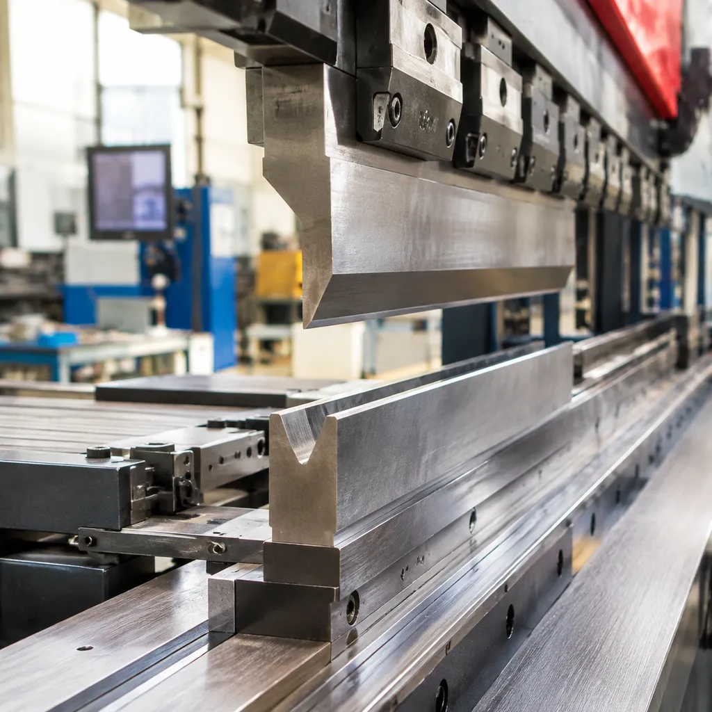
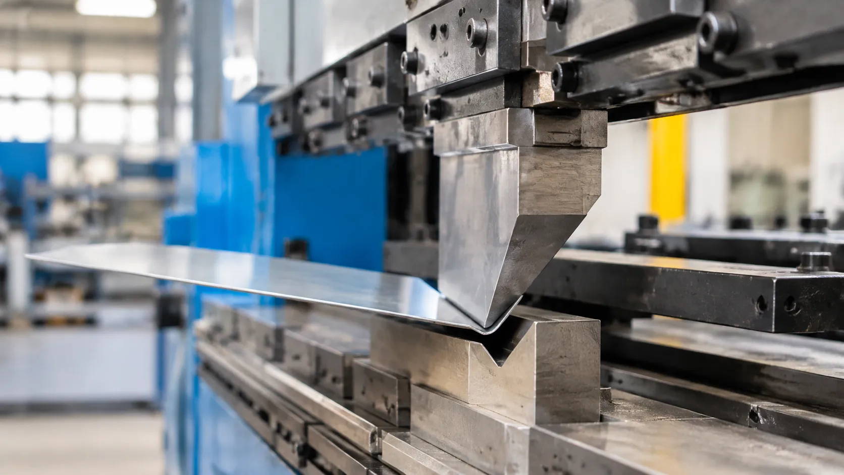
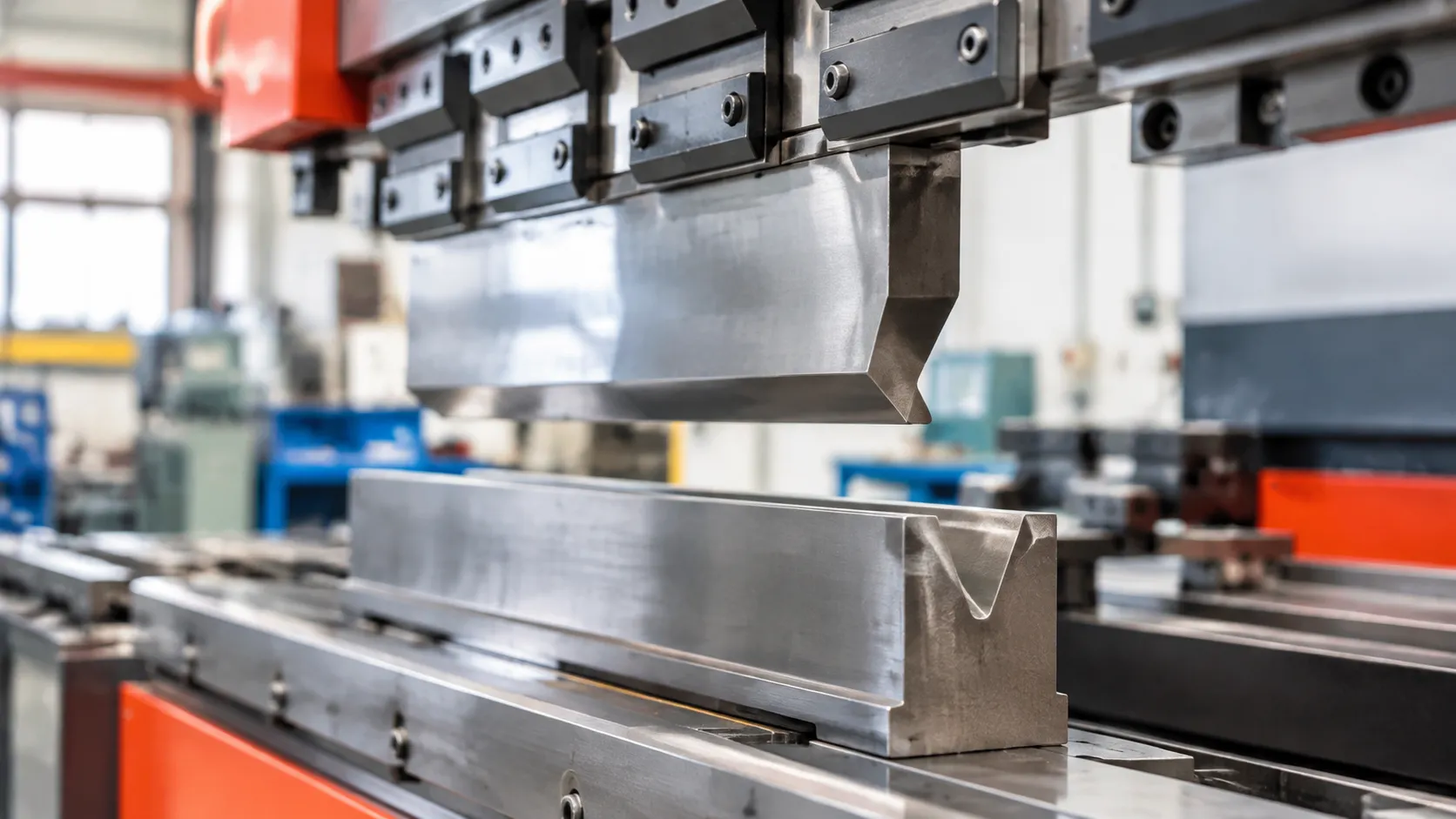
At CAMT, we specialize in high-precision offset press brake tooling engineered to streamline complex sheet metal forming. Our tools are designed to produce a "joggle" or Z-bend in a single press brake stroke, effectively transforming what would typically require two separate setups into one efficient operation.
Eliminating Two-Hit Bending Bottlenecks
Traditional sheet metal offset bending often forces fabricators to perform individual 90-degree bends, requiring multiple tool changes or complex indexing. Our offset press brake tools eliminate these bottlenecks by forming both opposing bends simultaneously. By integrating the punch and die geometry into a unified system, we help shops:
Reduce cycle times significantly.
Minimize material handling between stations.
Eliminate the risk of alignment errors between sequential bends.
Dimensional Consistency and Flange Accuracy
We understand that repeatability is the cornerstone of quality manufacturing. Our tooling is built to ensure strict tolerance control, providing consistent joggle depth and flange length across every part in a production run. Whether you are working on high-volume enclosures or precision brackets, CAMT offset solutions provide the stability required to maintain part-to-part uniformity and aesthetic consistency in your final assemblies.
System Compatibility & Shank Configurations
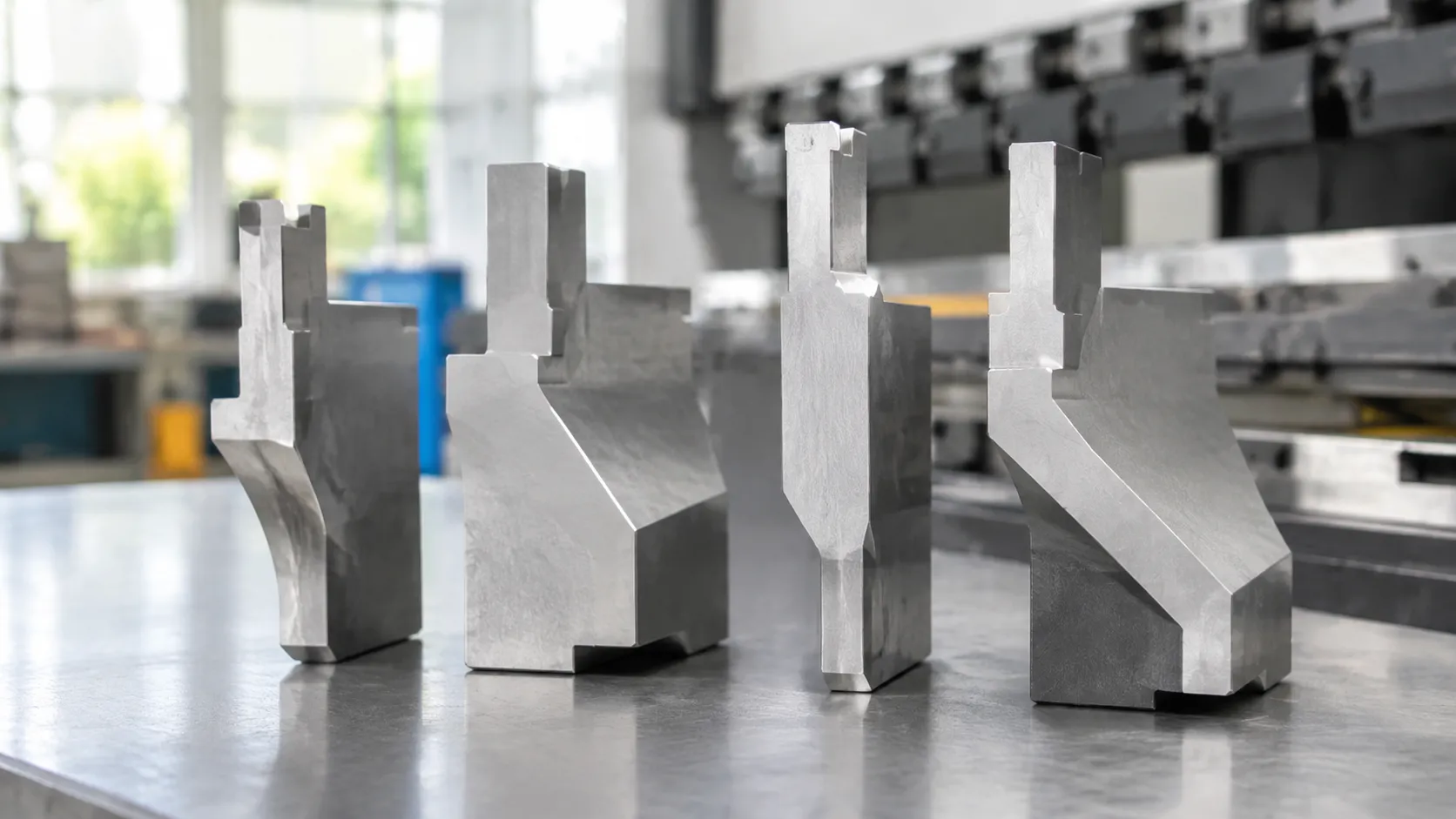
We engineer our offset press brake tooling to seat directly into your existing clamping systems without requiring custom bed modifications or secondary adapters.
Mounting Styles for Offset Press Brake Tools
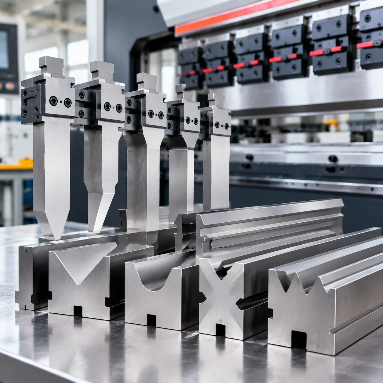
- European Style / Promecam Compatible: Ground with standard safety tangs and clamping profiles. Our European style press brake tooling configurations drop directly into standard mechanical or pneumatic tool holders, providing reliable vertical seating and rapid tool changeovers.
- American Traditional Style: Machined with standard 0.500-inch (12.7 mm) tangs to suit conventional American mechanical clamping bars. These robust shanks are ideal for high-tonnage joggle applications on domestic hydraulic machines.
- New Standard / Wila-Trumpf Compatible: Built for precision hydraulic and pneumatic clamping with automatic clamping pins or safety clicks. Our high-precision offset press brake tools align seamlessly with Wila-compatible tooling systems, ensuring self-seating alignment along the load line.
Sectionalized Tooling Lengths
To accommodate varying part widths and reduce operator fatigue, we supply standard solid lengths as well as fully segmented sets. Sectionalized profiles allow you to build custom bend lengths on demand or clear tight return flanges.
- Standard Solid Lengths: 515 mm and 835 mm solid sticks for continuous profile forming.
- Segmented Sets: Pre-cut sections (including left and right ear/horn segments) that let you configure specific forming widths in seconds without taking tools to a cut-off saw.
- Ergonomic Handling: Individual short segments keep piece weight manageable for a single operator during fast changeovers.
Technical Specifications & Sizing Matrix
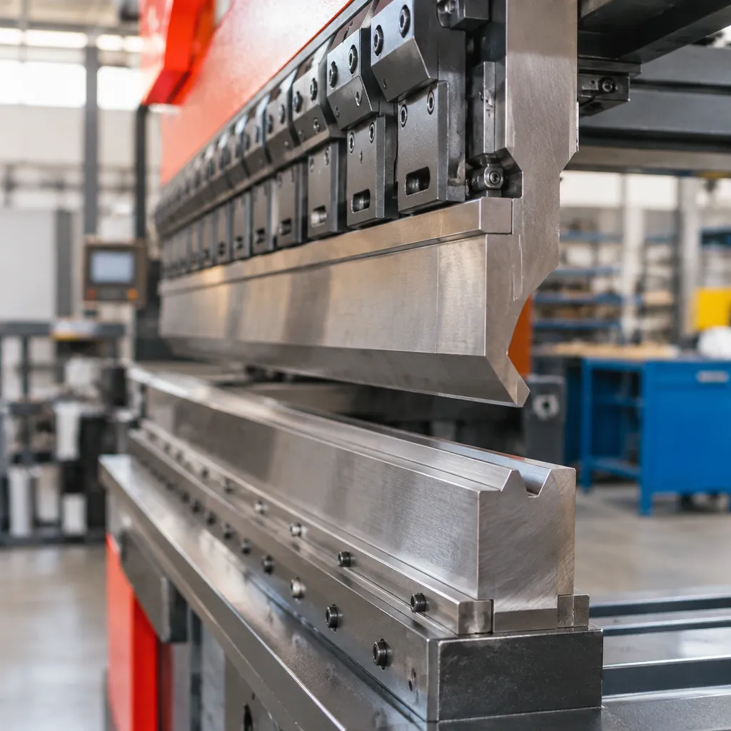
Selecting the right offset press brake tooling requires matching your target joggle depth directly to sheet thickness and machine capacity. We engineer standard offset press brake tools to maintain consistent step profiles across light-gauge electronics enclosures and heavy structural panels.
Standard Offset Range (1.0 mm to 15.0 mm)
The sizing matrix below outlines standard dimensional parameters for solid offset tooling setups:
| Offset Dimension (Z-Step) | Sheet Thickness Capacity (Mild Steel) | Minimum Flange Width | Typical Profile Type |
|---|---|---|---|
| 1.0 mm – 2.0 mm | 0.5 mm – 1.0 mm | 6.0 mm | Solid / Integral Punch & Die |
| 2.5 mm – 4.0 mm | 0.8 mm – 1.5 mm | 8.5 mm | Solid / Integral Punch & Die |
| 5.0 mm – 7.0 mm | 1.0 mm – 2.0 mm | 12.0 mm | Solid / Multi-V Compatible |
| 8.0 mm – 11.0 mm | 1.5 mm – 3.0 mm | 18.0 mm | Split Body / Heavy-Duty |
| 12.0 mm – 15.0 mm | 2.0 mm – 4.0 mm | 24.0 mm | Split Body / Heavy-Duty |
For specific profile matching, our dedicated offset punches provide precise force distribution along the bend line to prevent plate distortion during forming.
Replaceable Insert & Adjustable Offset Tooling
For job shops handling frequent small-batch runs with varying step heights, dedicated solid dies can drive up tooling storage and changeover costs. We solve this bottleneck by utilizing insert-based systems and adjustable press brake dies for precision metal bending.
- Modular Insert Holders: Mount hardened tool-steel inserts into a universal master holder to alter offset dimensions without buying an entirely new tool set.
- Shim-Adjustable Spacers: Fine-tune z-bend depths in fractional increments to compensate for varying material springback and batch thickness deviations.
- Rapid Changeovers: Swap worn working edges or adjust joggle steps directly on the machine bed, cutting setup times by up to 60%.
- Cost Efficiency: Replace only the high-wear contact edges rather than entire monolithic blocks when running abrasive or high-tensile sheet materials.
Material Metallurgy & Hardening Standards for Offset Press Brake Tools
Offset bending subjects tooling to severe lateral thrust and concentrated compressive loads across two bend lines simultaneously. To prevent tool deflection, premature shoulder wear, or catastrophic cracking, we hold our offset press brake tooling to rigorous metallurgical benchmarks.
Premium 42CrMo Tool Steel
Every set of our offset press brake tools is manufactured from vacuum-degassed, forged 42CrMo chromium-molybdenum alloy steel. Selected for its exceptional yield strength and deep-hardening properties, this substrate absorbs high tonnage shocks without warping:
- Tough core matrix: Resists bending stresses and fractures during heavy-gauge joggle operations.
- Structural stability: Maintains dimensional stability through millions of cycles, as outlined in our press brake die material guide.
- Superior fatigue resistance: Eliminates micro-fissuring at the critical step transition zones where stresses concentrate.
High-Frequency Induction Hardening
To ensure long-term durability against abrasive friction and galling, our contact surfaces undergo targeted high-frequency induction hardening:
- Targeted hardness depth: Critical working zones (shoulders, radii, and contact faces) achieve a surface hardness of 56–60 HRC to a depth of 2–3 mm.
- Ductile core preservation: The body retains a tough core (approx. 28–32 HRC), balancing extreme wear resistance with impact absorption.
- Extended edge life: Minimizes radius breakdown, preserving consistent offset step heights across large production runs.
CNC Precision Grinding
Consistency across sectionalized tooling requires strict machining tolerances. After heat treatment, our hardened offset dies pass through multi-axis CNC grinding centers:
- Profile tolerance: Ground to within ±0.01 mm across critical working profiles for exact interchangeability.
- Parallelism & alignment: Precision-matched punch and die profiles eliminate parallel runout, ensuring identical Z-bends whether bending short brackets or joining multiple sectional lengths.
- Surface finish: Ground to a fine mirror finish (Ra le 0.4 μm) to minimize friction drag and reduce part marking on sensitive sheet materials.
Tonnage Estimation & Forming Considerations for Offset Press Brake Tooling
Running offset press brake tooling requires substantially more machine capacity than standard single-bend setups. Because a single stroke creates two opposing bends simultaneously, the press brake must overcome double the material resistance in a restricted die pocket.
Understanding Tonnage Multipliers for Offset Forming
When switching to offset press brake tools, never use standard single-V tonnage calculations. Offset operations inherently require severe coining or high-load bottoming to establish the vertical step without distortion.
- Single-Bend Baseline: Calculate the standard tonnage required for an equivalent V-die opening using our press brake V-die chart and tonnage guide.
- The Offset Multiplier: Multiply that standard baseline tonnage by 2.5 to 3.5.
- Bottoming Loads: Achieving a sharp 90-degree step with tight inner radii forces full metal-to-metal contact, easily pushing tonnage toward the upper safety boundary. Always cross-check machine limits against the European press brake die rating guide for tonnage safety to avoid fractured shanks or deformed machine beds.
Material Thickness vs. Minimum Offset Rules
To form a clean Z-bend without shearing or slipping, the target offset depth (H) must match the sheet metal thickness (T). Violating minimum ratios leads to wall distortion and ruined profiles.
| Sheet Thickness (T) | Minimum Recommended Offset (H) | Typical Forming Method |
|---|---|---|
| 0.8 mm – 1.2 mm | 2.5 × T | Single-stroke coining / semi-bottoming |
| 1.5 mm – 2.0 mm | 3.0 × T | High-tonnage bottoming |
| 2.5 mm – 3.2 mm | 3.5 × T | Heavy-duty hydraulic offset forming |
| 4.0 mm+ | ≥ 4.0 × T | Extended-shoulder custom offset dies |
Rule of thumb: If the required offset height is less than three times the material thickness, standard offset forming dies will squeeze and crush the web rather than form crisp, parallel bends.
Grain Direction, Cracking Risks, and Springback Management
Forming two parallel bends simultaneously magnifies material flaws:
- Forming Across the Grain: Whenever possible, run your bends perpendicular to the sheet metal rolling grain. Bending parallel to the grain sharply increases the risk of tensile cracking along the outer radius of both step corners.
- Managing Dual Springback: Each bend in a Z-profile retains residual stress. In traditional setups, you can correct each angle independently. With Z bend press brake tooling, the angle and depth are set into the solid tool steel. We machine a built-in pre-compensation angle into our punch and die profiles to absorb standard springback, ensuring the resulting web stays flat and the flanges remain parallel.
- High-Yield Materials: For stainless steel or high-tensile alloys, springback increases drastically. Use wider offset clearances and higher tonnages to firmly set the step without introducing side-thrust deflection to the machine ram.
Common Industrial Applications for Offset Press Brake Tooling
Fabricators rely on our offset press brake tooling whenever high-run parts require flush seams, clearance steps, or overlapping lips without the labor cost of two consecutive hits. By delivering two parallel bends in a single stroke, our offset press brake tools drive efficiency across several core sheet metal manufacturing sectors:
- Electrical Enclosure Door Seams: We form clean overlap lips, drip channels, and gasket recesses on control cabinet doors. Single-stroke forming keeps the seal mating surface completely flat, preserving tight NEMA and IP enclosure ratings.
- Electronic Chassis Covers and Sliding Brackets: Server rack trays, modular computer chassis, and power supply covers use shallow joggles to clear surface-mounted components and create smooth slide-in channels.
- Automotive Mounting Brackets: Stamped and laser-cut chassis brackets, battery tie-downs, and sensor mounts require rigid Z-profiles. Using our hardened offset press brake tooling prevents part distortion and holds precise hole-to-hole centerlines across production batches.
- Architectural Cladding Joints: Metal facade panels, column wraps, and siding reveal joints demand long, uniform joggles. Forming these steps consistently prevents sheet warping along the bend axis.
When transitioning parts from standard V-bending to single-stroke joggles, consulting our press brake die opening guide and selection tips ensures you match material thickness to proper tool clearances and press tonnage limits.
Custom Offset Press Brake Tooling Engineered by CAMT
Standard step dies do not solve every sheet metal forming challenge. When part geometries demand non-standard Z-bends, tight flange tolerances, or work with high-tensile alloys, we design and manufacture custom offset press brake tooling tailored to your exact production requirements.
Tailored Depth, Radius, and Angle Configurations
We configure every critical dimension of our custom offset press brake tools to match your target material and part profile:
- Custom Offset Depths: We build continuous single-stroke dies for drop heights ranging from ultra-shallow sub-millimeter steps to deep drops exceeding 25 mm.
- Targeted Punch Radii: To prevent sheet fracturing on high-yield materials, we optimize the tip geometry based on proven press brake punch radius selection practices.
- Springback Compensation Angles: High-strength steel and structural aluminum often require acute relief. We modify die walls down to 85° or 88°, incorporating principles from our press brake die angles guide for springback to achieve exact 90° finished profiles.
- Asymmetrical Flanges: Punches and dies engineered with mismatched shoulders to yield uneven step bends without part collision.
| Customization Parameter | Standard Range | Custom CAMT Engineering Limits |
|---|---|---|
| Offset Depth (Step) | 1.0 mm – 15.0 mm | Up to 35.0 mm (application-specific) |
| Forming Angle | 90° Fixed | 30° to 175° Custom Form Profiles |
| Tip / Die Radius | 0.6 mm – 2.0 mm | Fully custom matched to bend radii |
| Tool Lengths | Standard segmented | Up to 4100 mm solid or custom cut |
Tooling Design Verification Process
Every custom offset forming die goes through a rigorous four-step validation sequence before entering CNC production:
- CAD Simulation & Clearance Analysis: We review your 3D component files to confirm that your return flanges and side panels clear the punch body and die shoulder during the full stroke cycle.
- Tonnage & Stress FEA: We run finite element analysis on the proposed die profile to verify that the bending loads remain within safe machine tonnage thresholds and do not exceed the yield point of the tool steel.
- Material Behavior Calibration: We adjust the die clearances based on your specific material grade, tensile strength, and sheet thickness variations.
- Precision CNC Profiling & Hardening: Following verification, we machine the profile from premium 42CrMo, deep-harden the wear faces to 50–55 HRC, and finish-grind critical contact surfaces to standard machining tolerances.
Ordering Guide & RFQ Submission for Offset Press Brake Tooling
Getting the right offset press brake tooling for your machine comes down to providing exact part and press brake parameters up front. When you order standard or custom offset press brake tools, sharing your bending requirements early prevents costly tooling rework, clearance issues, and unexpected tonnage overloads.
Review our comprehensive press brake die selection guide for precise bending if you need help matching punch geometries to your specific sheet metal profiles.
Technical Checklist for Inquiries
To ensure we quote and manufacture the exact single-stroke joggle tool or offset punch and die set for your production run, prepare the following specifications for your RFQ:
- Sheet Metal Profile: Exact material type (mild steel, stainless steel, aluminum) and tensile strength.
- Sheet Thickness (t): Exact gauge or millimeter thickness, including material tolerance ranges.
- Required Offset Height (Z): Inside or outside step dimension, measured from face to face.
- Flange Angles: Standard 90° opposing bends or custom obtuse/acute angles.
- Tooling Length & Sectioning: Total required length (e.g., 500 mm, 835 mm, full bed length) or specific segmented cuts.
- Machine Clamping Interface: Clamping style utilized on your hydraulic press brake (European/Promecam, American Standard, or New Standard/Wila-Trumpf).
- Machine Capacity: Available maximum press brake tonnage per meter/foot and machine open height.
- Part Drawings: 2D cross-section drawings (DXF/DWG/PDF) showing adjacent flanges to avoid interference.
Request Your Custom Offset Die Quote
We engineer and deliver precision-ground offset forming dies built to your exact job specifications. Send your dimensional prints, machine shank preferences, and target production volume to our tooling engineers. We analyze your material limits, calculate forming tonnages, and return a verified quote with lead times within 24 business hours.