
Formula details
Product Details
Overview
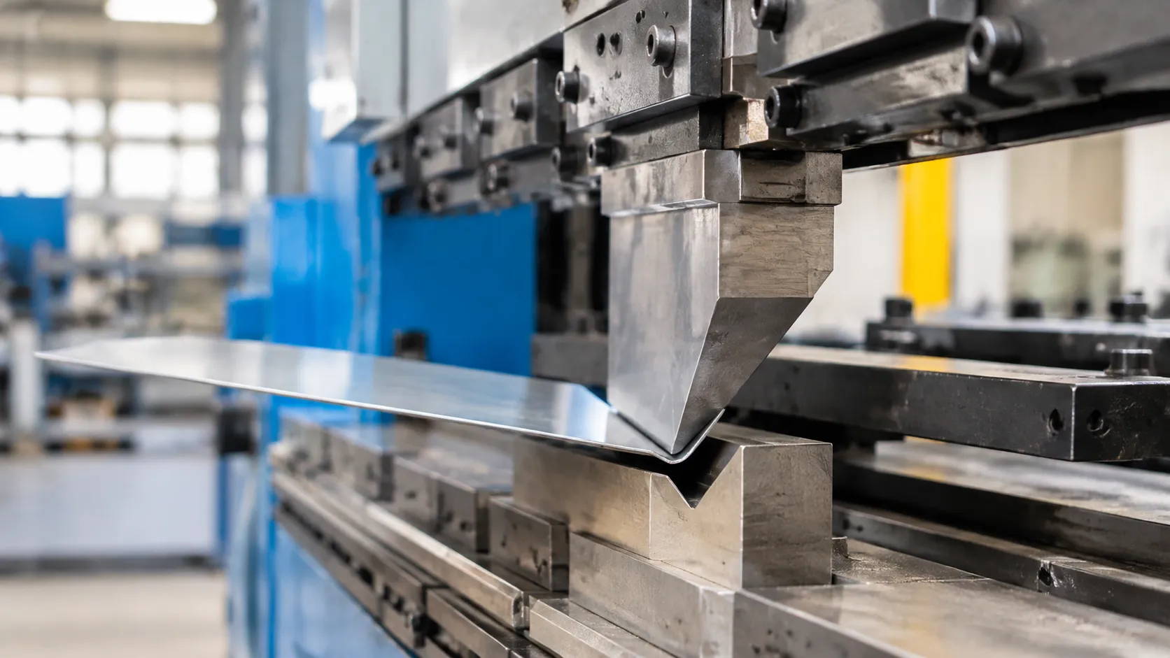
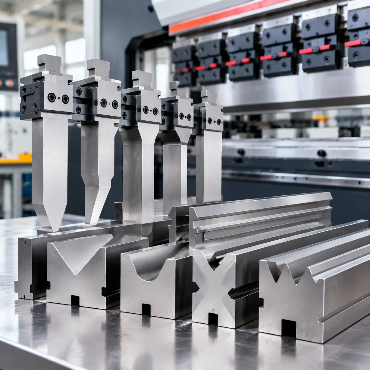
Upper Punches for Universal and Deep-Box Bending
Standard Straight Punches for 90-Degree Air Bending and Bottoming
Our standard straight punch profiles deliver balanced load distribution for everyday sheet metal fabrication:
- Versatile Forming: Designed for 90-degree air bending and bottoming operations across light to medium gauge steels.
- Precision Alignment: Ground working faces maintain centerline tolerance within +/-0.01 mm to eliminate profile taper.
- Direct Force Transmission: Symmetrical body geometry directs full machine tonnage straight through the tool centerline, preventing tip deflection.
Acute Angle Press Brake Punches to Eliminate High-Tensile Springback
High-strength materials require aggressive overbending to counter significant elastic recovery:
- Tip Angles: Available in 30°, 45°, and 60° profiles to overbend high-tensile sheet beyond nominal angles.
- Springback Control: Engineered specifically for air bending stainless steel and hard alloys that demand up to 15° of overbend compensation.
- Narrow Profile: Compact punch nose geometry ensures deep penetration into matching acute angle press brake dies.
Gooseneck Punches for Deep-Channel and Return-Flange Clearance
Deep U-channels and secondary return bends require substantial throat relief:
- Deep Recessed Relief: Large cutout clearance lets existing return flanges swing clear during secondary and tertiary hits.
- Box and Pan Capability: Deep-profile relief supports four-sided box forming without edge-crushing adjacent walls.
- Rigid Webbing: Reinforced back spine balances throat depth with load capacity, preventing tool flex under higher tonnages.
Sash and Narrow-Jaw Punches for Tight Enclosure Profiles
Forming narrow seams and miniature enclosures demands extreme tool clearance:
- Thin-Profile Body: Extended straight-drop nose reaches inside restricted channels, switchgear boxes, and narrow lighting troffers.
- Anti-Collision Design: Ultra-compact jaw profile clears tightly folded seams during rapid closure cycles.
- Targeted Applications: Optimized for precision electronics enclosures, architectural trim, and tight-radius cabinet manufacturing.
Heavy-Duty Radius Punches to Prevent Outer-Fiber Sheet Tearing
Bending thick plate and temper-grade aluminum requires broad contact radii to prevent surface rupture:
- Stress Relief: Large-radius punch noses (R3.0 mm up to R25.0 mm and above) evenly distribute tensile strain across the outer bend radius.
- Surface Preservation: Eliminates sharp grooving, centerline thinning, and sheet cracking in high-yield structural alloys.
- Heavy Tonnage Support: Solid-shank body geometry delivers maximum resistance against peak tonnages on thick structural plate.
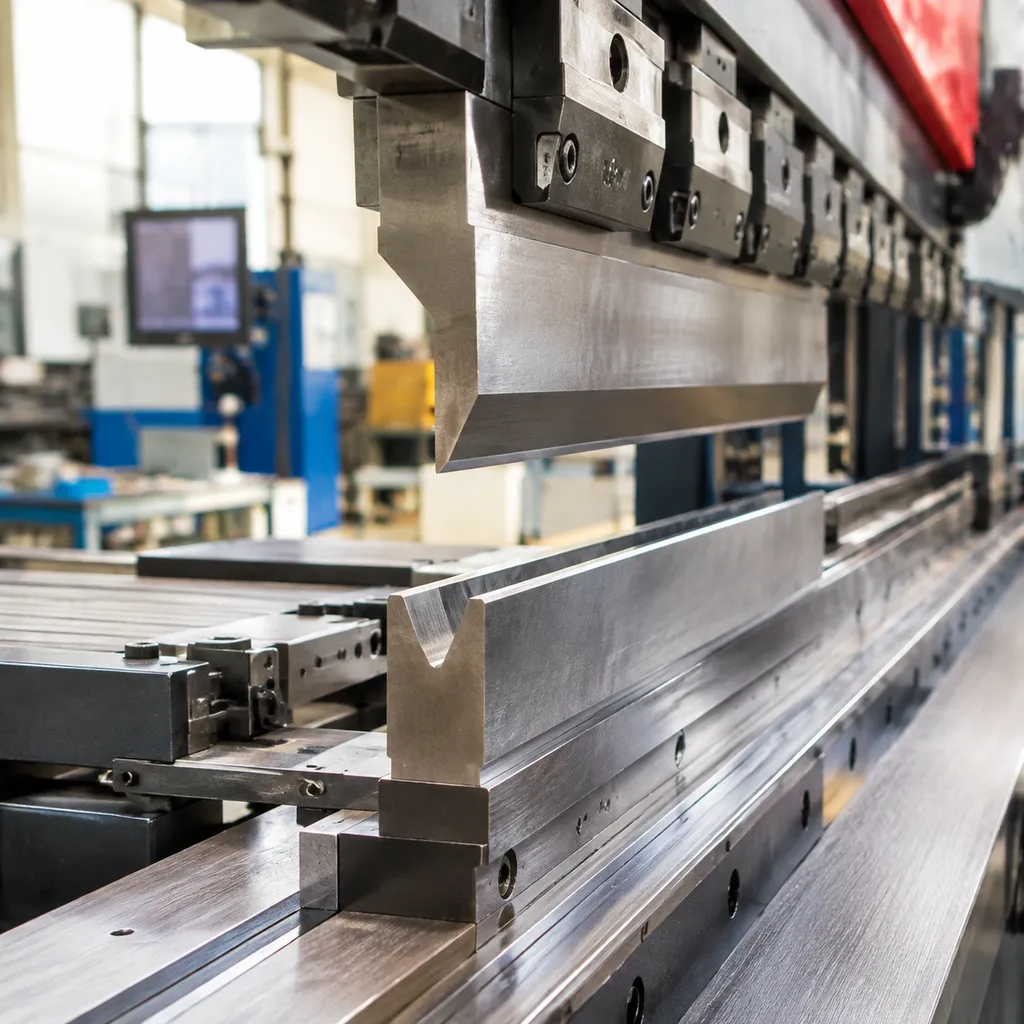
Our press brake tooling punch and die configurations integrate seamlessly with standard clamping systems, giving fabricators reliable tooling setups for universal job shop production and specialized high-volume runs.
Structural Lower Dies for High-Precision Air and Bottom Bending
Every bending process relies on structural stability at the bed. A properly matched press brake tooling punch and die setup prevents centerline deflection, reduces tonnage demand, and protects your parts from unnecessary cosmetic damage.
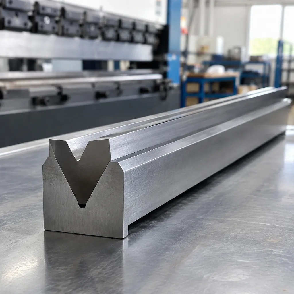
Single-V (1-V) Precision Dies with Alignment Safety Tangs
We grind our single-V dies with integrated safety tangs to eliminate side-slip and lock the tool directly into the bed centerline. Engineered for high-load air bending and bottoming, these solid-base blocks absorb heavy vertical stress while maintaining precise shoulder radii. When running demanding daily production, our press brake bottom dies give you the exact shoulder-to-tang consistency required for fast, accurate setups across the entire machine length.
Double-V (2-V) Reversible Die Blocks for Multi-Gauge Setups
For shops handling frequent job turnovers, our reversible 2-V die blocks save critical setup time. Flipping the block gives operators immediate access to two distinct V-openings without having to lift full sets off the machine.
- Dual Openings: Optimized for rapid switching between thin sheet and medium gauges.
- Symmetrical Centerlines: Graded shoulders maintain exact reference points on both sides.
- Balanced Hardening: Uniform surface treatment prevents warped edges during high-tonnage runs.
Multi-V and Self-Centering Die Blocks for Heavy Plate Fabrication
Thick plate fabrication demands extreme structural resistance. Our multi-V die blocks feature wide, reinforced openings designed to handle high-yield steels without wall spreading. Self-centering designs seat firmly against the machine bed, keeping your lower tool completely aligned with the upper punch during heavy hydraulic press cycles.
Hemming and Flattening Combination Dies for Teardrop and Flat Seams
Running two operations on separate machines slows down production. Our combination hemming sets handle both the acute pre-bend and the final flattening pass in a single station. Using a specialized 30-degree press brake die for air bending and hemming, operators can create clean teardrop seams and zero-gap flat hems without swapping out the press brake tooling punch die assembly between strokes.
Non-Marking Polyurethane Inserts and Roll-Die Systems
Forming pre-painted panels, mirror-finish stainless steel, or architectural aluminum requires zero tool friction. We supply replaceable polyurethane die pads and rotating roll-die systems that eliminate direct steel-on-sheet contact:
- Polyurethane Film & Inserts: Cushion the part inside the V-opening to wipe out tool mark lines.
- Hardened Roll-V Benches: Smooth, spinning shoulder rollers reduce drag, dropping the required forming tonnage and protecting delicate finishes.
Equipping your press brake with the right punch and die press brake tooling ensures rigid alignment, longer tool life, and consistent bend angles from the first part to the last.
Clamping Configurations and Press Brake Mounting Standards
Tooling alignment issues, uneven bend angles, and slow changeovers usually trace back to one factor: improper mounting interfaces. A precision-ground punch and die set only performs as well as the clamping system holding it securely against the beam under load. We manufacture press brake tooling punch and die setups across all major universal and proprietary mounting standards to match your specific press brake configuration without mechanical play.
European and Amada-Promecam Style Safety-Hook Tooling
The European standard (Amada-Promecam) remains the most widely deployed system on modern job-shop floors.
- Punch Tang: Features an 8.4 mm thick tang with a built-in safety groove or spring-loaded mechanical safety hook.
- Safety Mechanism: The safety hook prevents heavy punches from dropping during tool unclamping, protecting operators and lower die surfaces.
- Lower Die Alignment: Lower dies utilize a standard 12 mm x 20 mm safety tang that drops directly into lower bed holders, self-centering under initial clamping load.
Trumpf-Wila New Standard Self-Seating Tooling
For shops focused on automated tool changes and rapid setups, Trumpf-Wila New Standard systems deliver unmatched speed and repeat precision.
- Self-Seating Pins: Integrated pneumatic or hydraulic clamping pins engage the punch grooves directly, lifting and seating the punch tight against the beam shoulders with zero operator adjustment.
- Vertical Loading: Punches and dies click straight up and down into position, completely eliminating the need to slide long segments in from the side of the machine.
- High Working Load: Rated for heavy-duty tonnages up to 250–300 tons/meter along the centerline without shoulder deformation.
American Conventional 0.500-Inch Tang Systems
American conventional tooling remains a rugged, reliable choice for traditional mechanical and hydraulic press brakes across North America.
- Standard Dimension: Punches feature a solid 0.500-inch (12.7 mm) straight tang secured by mechanical clamp plates and set screws.
- Bed Mounting: Bottom dies feature matching 0.500-inch tangs, locking into standard slot beds or flat holders.
- Durability: While manual alignment takes a bit more setup time compared to quick-change systems, the thick tang handles aggressive off-center loading on structural plates.
Bystronic and LVD Direct-Mounts and Quick-Change Adapters
Specialized machines require specific clamping solutions to maintain precision centerline positioning.
- Direct Mounting: Engineered with proprietary push-button or side-clamp engagement pins specific to Bystronic and LVD hydraulic beams.
- Universal Conversion Adapters: If your shop operates mixed machine brands, our precision-ground adapter blocks convert American or European machines to run Trumpf-style punch die sets without losing shut height or machine stroke.
- Repeatable Centerlines: All adapter systems maintain strict +/-0.01 mm centerline alignment, allowing seamless integration across diverse punch and die press brake tooling configurations.
Industrial Metallurgy, Heat Treatment, and Grinding Tolerances
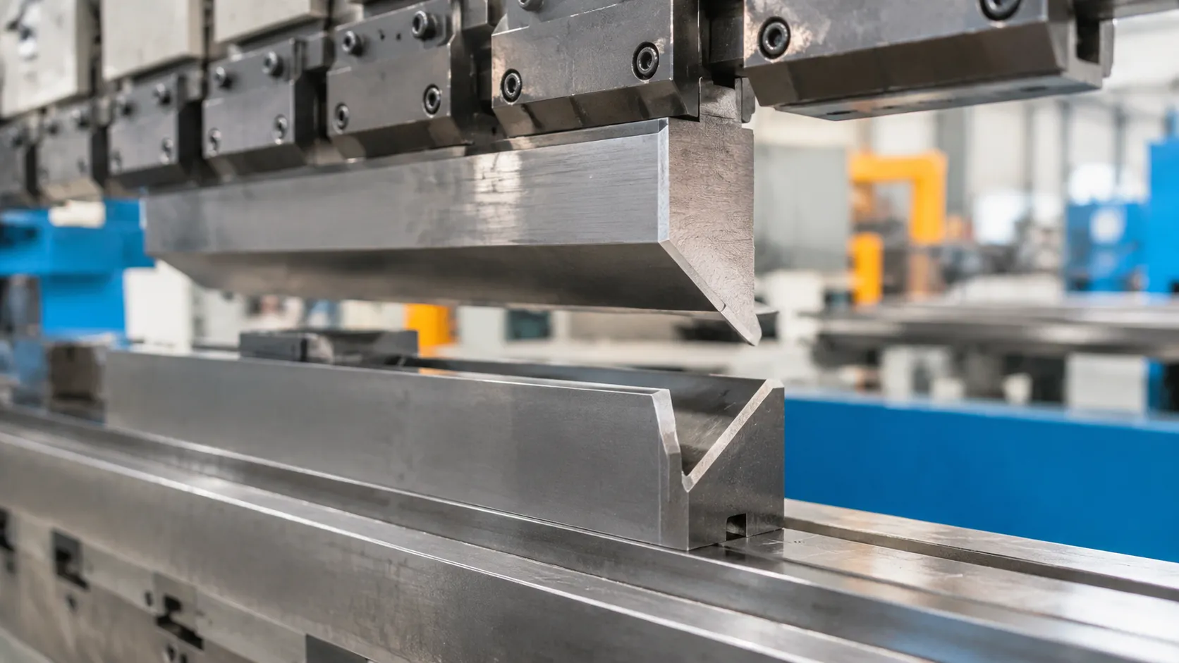
Tool longevity and bend angle repeatability depend entirely on core metallurgy, thermal processing, and finish grinding. When manufacturing industrial press brake tooling punch and die systems, we select materials and heat-treatment profiles that balance surface wear resistance with interior core toughness to eliminate tool breakage under high tonnages.
High-Wear Alloy Steels: 42CrMo, Cr12MoV, and SCM440
Selecting the right alloy dictates how your tooling withstands heavy mechanical loads, abrasive scales, and repetitive shock:
- 42CrMo (AISI 4140 equivalent): The industry benchmark for structural press brake tooling punch die components. It combines exceptional core tensile strength (over 1000 MPa) with high impact fatigue resistance, making it ideal for universal bending, high-tonnage forming, and general fabrication.
- Cr12MoV (AISI D2 equivalent): A high-carbon, high-chromium cold-work die steel tailored for extreme wear conditions. We deploy Cr12MoV for specialized bottoming dies, acute coin-bending tools, and high-abrasion applications where edge retention is vital.
- SCM440: An alternative chrome-molybdenum structural steel delivering balanced hardness and high torsional yield strength, preventing shank distortion during continuous production runs.
Evaluating alloy performance against your standard sheet metal thickness and tonnage demands is critical; consult our press brake V die chart and tonnage guide to verify mechanical load limits before tool selection.
| Steel Grade | Typical Hardness (Working Edge) | Core Hardness | Tensile Strength | Primary Use Case |
|---|---|---|---|---|
| 42CrMo | 52–58 HRC | 28–32 HRC | ≥ 1080 MPa | Universal punches, standard V-dies, segmented sets |
| Cr12MoV | 58–62 HRC | 55–58 HRC | ≥ 1470 MPa | Abrasive runs, hemming inserts, high-wear dies |
| SCM440 | 50–55 HRC | 26–30 HRC | ≥ 980 MPa | Heavy-duty structural tools, long solid punch blocks |
Deep-Induction Hardening vs. Through-Hardening
Heat treatment determines whether a tool deforms, chips, or shatters under side-load deflection:
- Deep-Induction Hardening: We apply high-frequency induction hardening specifically to the working shoulders of the dies and the critical punch tip radius. This achieves a case hardness of 52–58 HRC up to a depth of 3 mm to 5 mm, while keeping the tool core ductile (28–32 HRC). The ductile core acts as a shock absorber under severe pressure, preventing catastrophic shank fracturing.
- Through-Hardening: While through-hardened tooling provides uniform hardness throughout the entire cross-section, it increases brittleness. A minor machine overload or off-center bend can cause catastrophic tool snapping rather than localized edge wear. For standard and heavy-gauge bending, our induction-hardened 42CrMo press brake tooling delivers substantially greater operator safety and dynamic fatigue life.
CNC Precision Mirror-Grinding to ±0.01mm Centerline Alignment
Even premium metallurgical treatments fail if critical dimensions lack machine-ground precision. Our precision ground punch dies undergo multi-axis CNC surface and profile grinding under strict climate-controlled conditions.
- Centerline Tolerance: Precision-ground to within ±0.01 mm between the clamping tang, tool body, and punch tip centerline.
- Working Height Uniformity: Overall height variation kept strictly within ±0.01 mm along the entire working length, enabling seamless interchangeability between sectionalized segments without shimming.
- Mirror-Ground Radii: Punch tips and die entry shoulders feature a micro-finish surface (Ra < 0.4 µm), minimizing friction, preventing galling on protective film sheets, and maximizing the service life of both your punch and die press brake tooling setup.
Tooling Lengths, Ear-Cuts, and Segmented Configurations
Running full-length sheet runs requires rigid, solid sections, while four-sided box forming demands precise clearances. We manufacture our press brake tooling punch and die inventory in modular dimensions to let operators build any bend length in seconds without wasting time on custom shimming.
Standard Solid Tooling Lengths (835 mm and 415 mm)
For continuous production, long flange passes, and standard bending runs, we provide solid-length sections ground to strict tolerances:
- 835 mm Full-Length Sections: The industrial standard for wide sheet forming, providing maximum beam stability and uniform load distribution.
- 415 mm Half-Length Sections: Ideal for shorter parts, prototype prototyping, or pairing alongside longer segments to match specific machine bed lengths.
- Matched Working Heights: Every solid stick is CNC precision-ground so our punches and American-style press brake tooling can be aligned side-by-side with zero height discrepancy across the bed.
Full Segmented Punch Sets with Left and Right Horn Ear-Cuts
Deep returns and return flanges will collide with standard punch bodies. To clear upright flanges during box and pan folding, our segmented press brake tooling punch die sets include engineered horn cuts:
- Standard Multi-Piece Sets: Typically sectioned into practical widths (10, 15, 20, 40, 50, 100, 200, 300, and 400 mm combinations) to assemble any target bend length.
- Relieved Left and Right Ear-Cuts (Horns): Both ends feature 100 mm horned sections that extend past the upper clamp, preventing tool interference when finishing the final return bends of a 4-sided enclosure.
- Interchangeable Profiles: Horn cuts are standard on our straight profiles as well as deep-relief gooseneck punches to ensure full clearance on narrow channels.
Custom Width Sectionalizing for Complex Pan and Box Bending
When standard segment step-ups do not clear specific interior box depths or narrow offset profiles, we build custom segmented punch and die press brake tooling:
- Bespoke Cut Widths: Precision wire-EDM sectioning tailored to your exact part drawings down to narrow single-millimeter increments.
- Numbered Precision Sets: Segments are ground together in a single clamping pass, individually numbered, and mapped for exact installation sequence to preserve centerline accuracy.
- Quick-Swap Segmentation: Individual sections feature safety clicks or quick-release tang cuts, allowing fast repositioning directly across your machine's beam without dropping tooling into the lower bed.
Technical Selection Guide: Die Opening and Tonnage Calculations
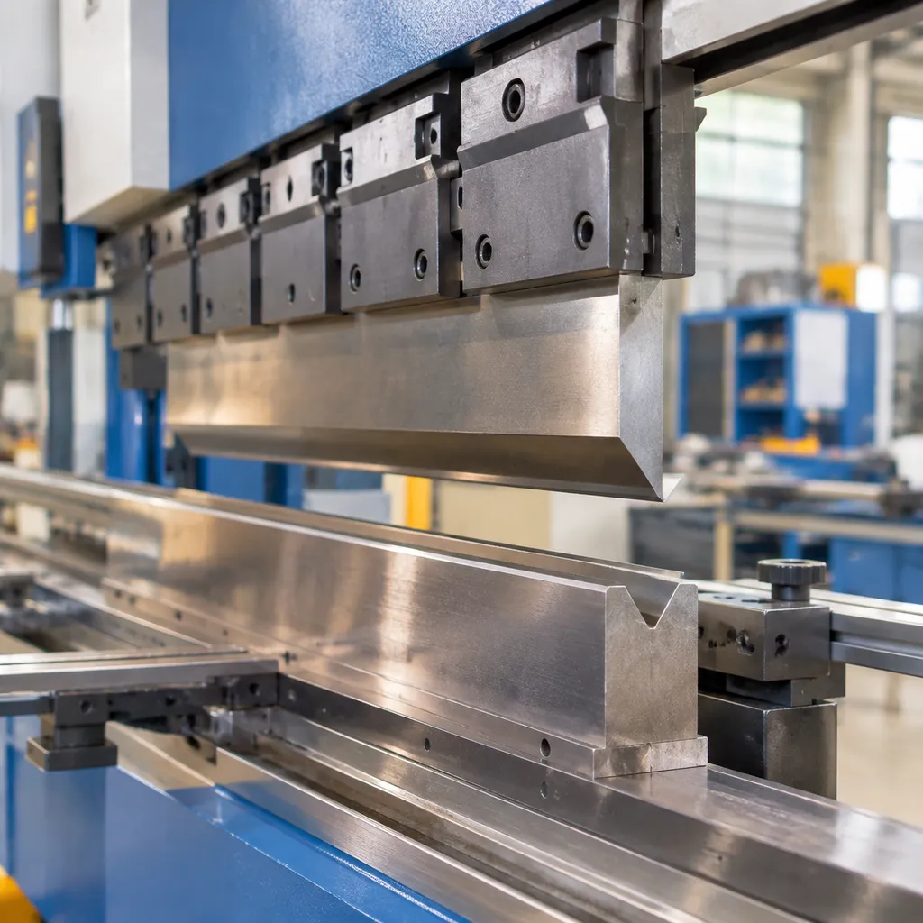
V-Opening Selection Formulas Based on Sheet Metal Thickness
Choosing the correct V-width directly impacts the bend radius, tonnage demand, and minimum flange length. When sizing hydraulic press brake dies for standard air bending:
- Sheet thickness (t) up to 2.5 mm: V = 6 to 8 × t (V = 8 × t is the industry baseline)
- Sheet thickness (t) from 3 mm to 8 mm: V = 8 to 10 × t
- Sheet thickness (t) 9 mm to 12 mm: V = 10 to 12 × t
- Heavy plate (t > 12 mm): V = 12 × t to minimize load limits
Using a die opening that is too narrow spikes required forming tonnage, increasing wear on both the press brake bottom dies and the ram. For detailed layout rules on specific gauges, check our press brake die selection guide for precise bending to align your tooling with your sheet tolerances.
Air Bending Tonnage Calculation Table
The standard formula to estimate air bending tonnage per meter is:
- P = (650 × t² × L) / (V × 1000) (where P is metric tons, t is sheet thickness in mm, L is bend length in mm, and V is the die opening in mm, based on 450 MPa mild steel).
Stainless steel (304 / 316) requires roughly 1.5× the tonnage of mild steel, while aluminum requires about 0.5×.
| Sheet Thickness (t) | Recommended V-Die Opening | Mild Steel (450 MPa) Tonnage/Meter | Stainless Steel (304) Tonnage/Meter | Min. Inside Radius (Ri) | Min. Flange Length (b) |
|---|---|---|---|---|---|
| 1.0 mm | 8 mm | 8.1 t | 12.2 t | 1.3 mm | 5.5 mm |
| 1.5 mm | 12 mm | 12.2 t | 18.3 t | 2.0 mm | 8.5 mm |
| 2.0 mm | 16 mm | 16.3 t | 24.5 t | 2.6 mm | 11.5 mm |
| 3.0 mm | 24 mm | 24.4 t | 36.6 t | 4.0 mm | 17.0 mm |
| 4.0 mm | 32 mm | 32.5 t | 48.8 t | 5.3 mm | 22.5 mm |
| 6.0 mm | 50 mm | 46.8 t | 70.2 t | 8.0 mm | 35.0 mm |
Operating within these parameters ensures that your press brake tooling punch die setup runs well below maximum structural load limits, preserving ground working shoulders. For extreme plate workloads, refer to our specific recommendations on air bending bottom die opening for thick materials.
Punch Tip Radius Matching to Avoid Material Cracking
Matching the punch tip radius to your material grade prevents centerline coining, fracture along the bend line, and premature tool fatigue:
- Avoid sharp punch tips on high-yield sheets: If the punch tip radius is smaller than the natural inside bend radius (Ri = V / 6 to V / 8), the top punch acts like a wedge. This causes deep coining grooves, tensile tearing along outer sheet fibers, and concentrated stresses on the punch tip.
- Punch radius for mild steel: Match the punch tip radius as close to 1:1 with the material thickness as your inside radius specifications allow. Standard R0.8 mm, R1.0 mm, and R1.5 mm tips cover thin gauges without fracturing the bend line.
- Punch radius for stainless and high-tensile alloys: Use a punch tip radius at least equal to the material thickness (1.5× to 2× thickness on structural plates) to prevent outer-fiber micro-cracks and relieve stress on your precision ground punch dies.
- Centerline fatigue control: Undersized radii create high localized resistance, leading to hairline fractures along the punch tip centerline over continuous production cycles. Running a larger radius evenly distributes the press brake tooling punch and die load across the entire tool profile.
Custom Punch and Die Prototyping and Engineering Services
Standard tooling profiles cannot solve every fabrication challenge, especially when dealing with tight clearance envelopes, high-tensile alloys, or intricate forming geometries. When standard catalogs fall short, we design and manufacture custom press brake tooling punch and die profiles matched to your machine specs, backgauge clearances, and target tonnage limits. Through our dedicated custom tooling development department, we take non-standard concepts from digital part geometry to hardened, precision-ground tooling on your shop floor.
48-Hour Engineering File Review
We start every custom build directly from your production CAD data. You send us your profile drawings, and our tooling engineers evaluate the feasibility within two business days.
Accepted Formats: 2D profiles in .DXF and .DWG; 3D assemblies and solid models in .STEP or .IGES.
Application Review: We cross-check material yield strength, sheet thickness, bend angles, and required flange lengths against your press brake capacity.
Rapid Turnaround: You receive a preliminary tooling cross-section, working dimensions, and a firm manufacturing estimate within 48 hours.
Bending Simulation, Collision Analysis, and Springback Compensation
Tool deflection and machine collisions waste material and damage tooling. Before cutting tool steel, our team runs full virtual bending simulations on your proposed press brake tooling punch die sets.
Interference Checks: We map punch neck geometry against machine side frames, upper beams, and backgauge fingers to prevent tool-to-part contact on deep return flanges.
Springback Modeling: High-strength materials such as Domex or stainless steel exhibit significant angular recovery. We build calculated angular overbends directly into the punch tip and die shoulder geometries.
Tonnage Limits: We calculate load distributions across the tool centerline to protect your press brake cylinders and ensure maximum safe working cycles.
Custom Tooling for Offset, Corrugation, and Complex Radii
Single-stroke forming eliminates secondary handling operations, lowers cycle times, and maintains tight dimensional accuracy across production runs. We engineer custom punch and die press brake tooling for complex multi-bend operations:
Offset Joggle Profiles: Form two opposite bends simultaneously with precision-machined offset punches and matching bottom dies to hold exact Z-step dimensions in a single ram stroke.
Corrugation and Rib Forming: Deep-draw corrugated tooling designed to prevent sheet stretching and wrinkling across broad structural panels.
Special Large-Radius Sets: Custom modular punches paired with variable-relief bottom dies to achieve large radius sweeps in plate work without step-bending witness lines.
Segmented Custom Lengths: Precision wire-EDM sectioning tailored to clear existing side return flanges on specific enclosure boxes.
Frequently Asked Questions: Press Brake Tooling Punch and Die
How do I determine the right V-die opening for my material thickness?
For air bending, we match the lower V-die opening ($V$) directly to sheet thickness ($T$) and material tensile strength. Using the correct opening controls inner radius formation, minimizes tonnage requirements, and prevents tool deformation.
| Material Thickness ($T$) | Recommended V-Opening ($V$) | Typical Application |
|---|---|---|
| 0.5 mm – 2.5 mm | 6 × T to 8 × T | Precision sheet metal, tight radii |
| 3.0 mm – 6.0 mm | 8 × T to 10 × T | General structural fabrication |
| 6.0 mm – 12.0 mm+ | 10 × T to 12 × T | Heavy plate, high-tensile bending |
If the V-opening is too narrow, bending tonnage spikes drastically and risks cracking the sheet. If it is too wide, the bend angle loses consistency across the bed length.
What is the difference between European and Trumpf-Wila style clamping?
The distinction lies in shoulder engagement, load transfer, and clamping mechanism:
- European / Amada-Promecam Style: Features a standard safety tang (typically 0.500 in or standard European tang) clamped horizontally with manual set screws or pneumatic bars. Tooling seats against the bottom plate of the punch holder. Check our press brake die replacement for American and European styles when retrofitting legacy machines.
- Trumpf-Wila (New Standard) Style: Uses mechanical or hydraulic clamping pins engaging precision grooves on the punch shank. Tooling seats directly on the upper shoulders for self-aligning, pull-up seating that supports fast vertical tool changes and tighter tolerances.
Why is induction-hardened 42CrMo preferred over through-hardened tool steel?
We build heavy-duty press brake tooling punch die sets using 42CrMo (SCM440) alloy with deep-induction hardening on working areas.
Through-hardened tool steels (such as Cr12MoV or D2) reach 58–62 HRC entirely through the body, leaving them brittle under shock loads, off-center hits, or localized tonnage spikes. Deep-induction hardening delivers:
56–60 HRC working contact zones: Extreme wear resistance on punch tips and die shoulders.
28–32 HRC ductile core: High tensile strength that absorbs side thrust and deflection without fracturing the shank.
How can I prevent sheet scratching on polished stainless steel or aluminum?
Abrasive drag over hardened steel die shoulders causes direct surface galling on cosmetic materials. To eliminate sheet marking during air bending:
Protective Urethane Films: Apply adhesive non-marking protective film across the lower die shoulders to create a barrier between the tool and sheet.
Polyurethane Inserts: Fit steel die holders with high-density urethane die pads that compress and wrap around the sheet.
Roller Bearings / Rotabend Dies: Use lower dies equipped with rotating hardened inserts that turn with the workpiece as it forms, replacing sliding friction with rolling contact.
What causes punch tip damage and how do I calculate safe tonnage limits?
Punch tip deformation, pitting, or catastrophic fracturing happens when working tonnage exceeds the mechanical limit of the punch tip radius. The primary causes include:
Over-tonnage on small punch radii (e.g., forcing a 0.6 mm radius tip into heavy gauge plate).
Accidental bottoming or coining using tools engineered strictly for air bending.
Off-center tool loading that introduces heavy side thrust.
Before setting forming pressures on your punch and die press brake tooling, review our European press brake die rating guide for tonnage safety to verify load limits per meter. Never apply high machine tonnages against narrow, acute punch tips without matching the load capacity of the tool geometry.