A single worn or damaged die can ruin your bend accuracy and bring your entire metal fabrication shop to a grinding halt.
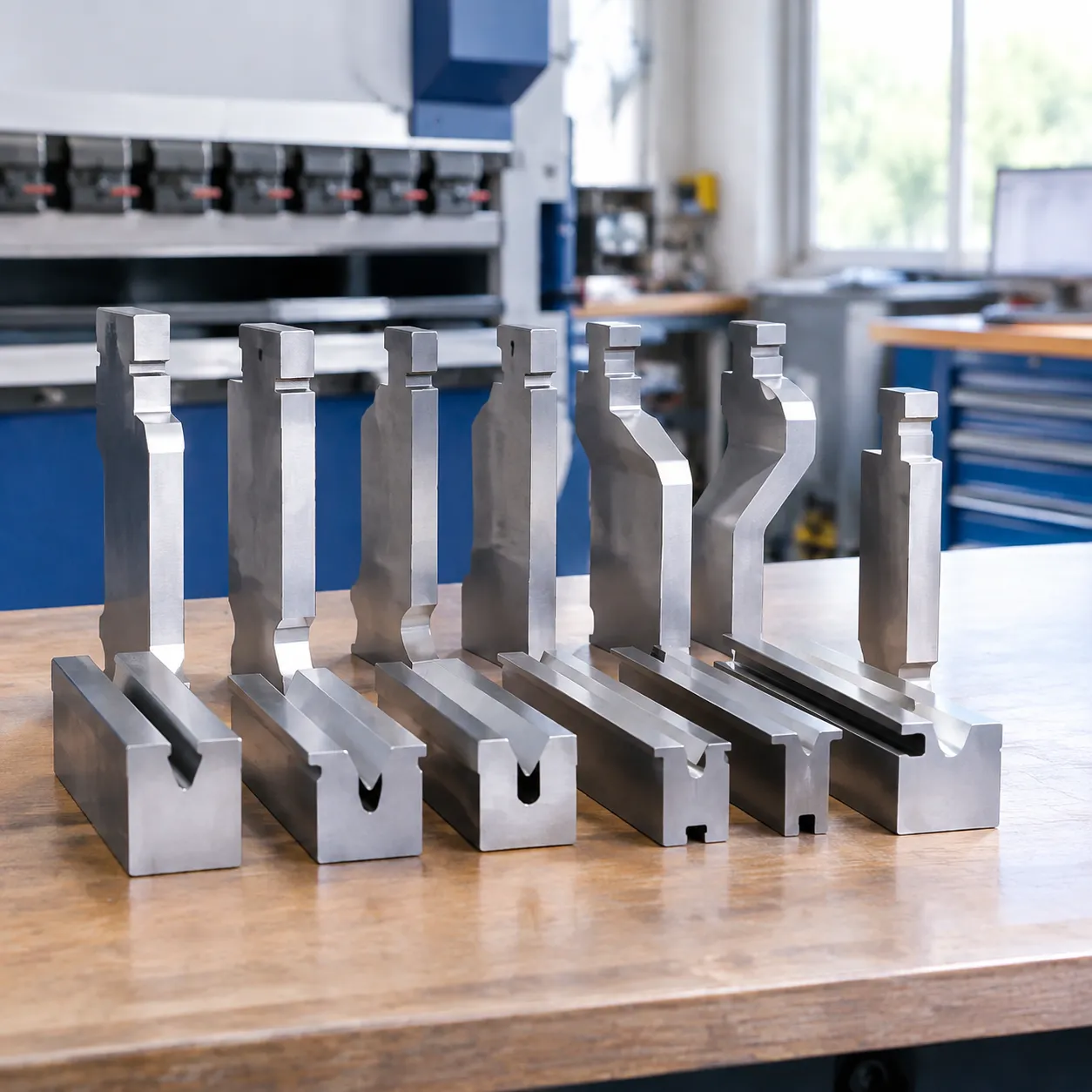
Finding the ideal press brake die replacement isn't just about buying parts—it's about matching your exact tooling style, whether you run American Precision, European/Amada, Trumpf, or Wila systems. From verifying strict tonnage limits to choosing mar-free polyurethane dies that protect polished stainless steel, picking the right replacement punch and V-die is critical for maintaining peak efficiency.
In this guide, you'll learn how to evaluate supplier compatibility, select durable tooling for legacy machines, and source the precise press brake tooling your shop needs to eliminate costly downtime.
Let's dive right in.
5 Signs Your Press Brake Die Needs Immediate Replacement
Angular Variation Across Long Bends
- Symptom: Angle drift between the center and outer ends of a long sheet metal workpiece.
- Root Cause: Shoulder radius wear exceeding a 0.1 mm tolerance loss.
- Impact: Uneven shoulder erosion alters the punch penetration depth required for uniform angles, introducing inconsistent springback across the full bend length.
Surface Marking and Galling
- Symptom: Deep pitting, drag marks, and micro-cracks along the V-groove shoulders.
- Root Cause: Breakdown of gall resistance leading to material pick-up.
- Impact: Microscopic metal transfer damages the die surface and scores sensitive sheet metal—especially polished stainless steel and aluminum.
Inconsistent Flange Dimensions
- Symptom: Flange lengths fluctuating even when backgauge positioning remains precise.
- Root Cause: Altered V-opening geometry caused by shoulder erosion.
- Impact: In air bending, the inside bend radius floats relative to the V-die opening width. As the opening widens from wear, the neutral axis shifts and alters your bend deduction calculations.
Cracking or Stress Lines on Part Radii
- Symptom: Sharp stress lines or material fractures forming along the outer part radius.
- Root Cause: Rough or uneven bottom radius profiles.
- Impact: Worn entry radiuses create concentrated friction points that score and fracture high-tensile sheet metal during forming.
Frequent Tonnage Overload Alarms
- Symptom: CNC controller triggering unexpected tonnage limit alarms on standard bends.
- Root Cause: Worn entry shoulders increasing material drag.
- Impact: Degraded shoulder profiles force hydraulic press brake systems to work harder, increasing required forming tonnage by up to 20% and exposing the ram and bed rail to potential deflection issues.
Technical Criteria for Selecting Replacement Dies
Material Grade & Thermal Treatment
We manufacture our bottom die replacement tooling using certified 42CrMo tool steel dies. Basic surface nitriding wears away quickly under repeat friction, whereas our deep induction hardened tooling achieves HRC 55–60 core hardness to maximize shoulder durability and gall resistance.
Dimensional Accuracy & Micro-Finish
Our precision ground press brake dies eliminate angular variation across full-length bends through strict manufacturing limits:
Dimensional Tolerance: Precision CNC ground to ±0.01 mm for complete section interchangeability.
Surface Roughness: Ra < 0.8 µm micro-finish on V-groove shoulders to minimize friction and part marking.
V-Die Selection Rules
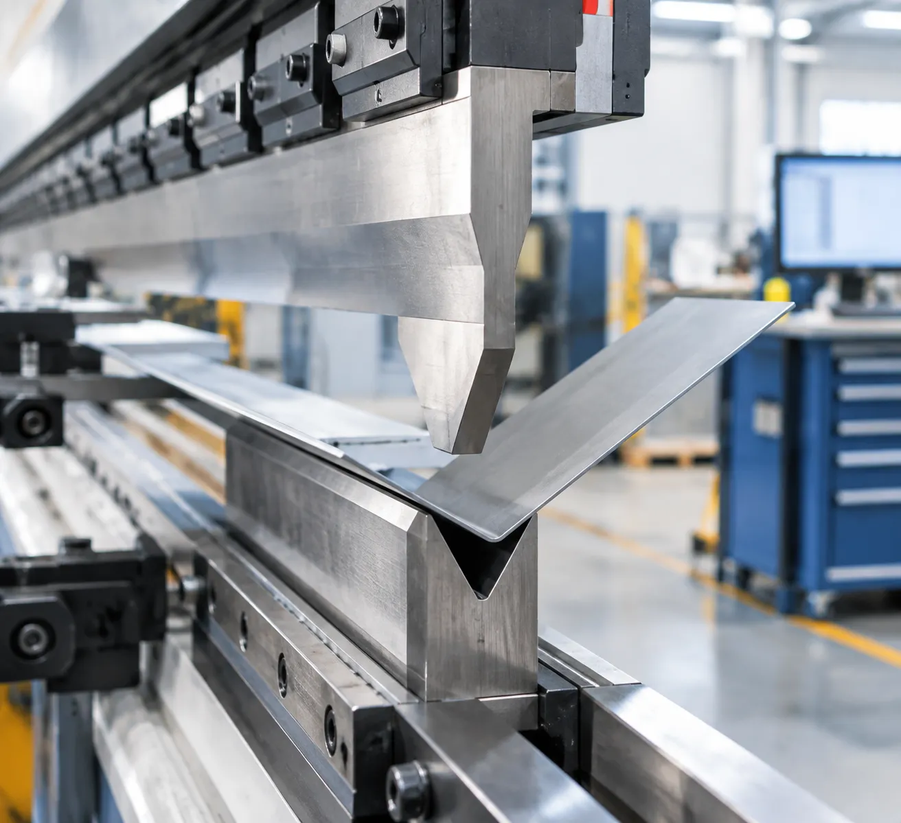
Applying the correct V-die selection rule maintains proper inside radius formation and keeps press tonnage within safe operating limits. Use our press brake die size chart and dimensions guide to match V-openings to your sheet metal specs.
| Material Spec & Application | Material Tensile Strength | Standard V-Die Opening Rule |
|---|---|---|
| Mild Steel (< 6 mm) | Standard (~450 MPa) | 8x Material Thickness (8t) |
| Thin Sheet / Soft Aluminum | Low Tensile | 6x Material Thickness (6t) |
| Stainless & High-Tensile Steel | High Tensile (> 600 MPa) | 10–12x Material Thickness (10–12t) |
| Heavy Plate (≥ 6 mm) | Structural Grade | 10–12x Material Thickness (10–12t) |
Tooling System Compatibility & Interface Verification
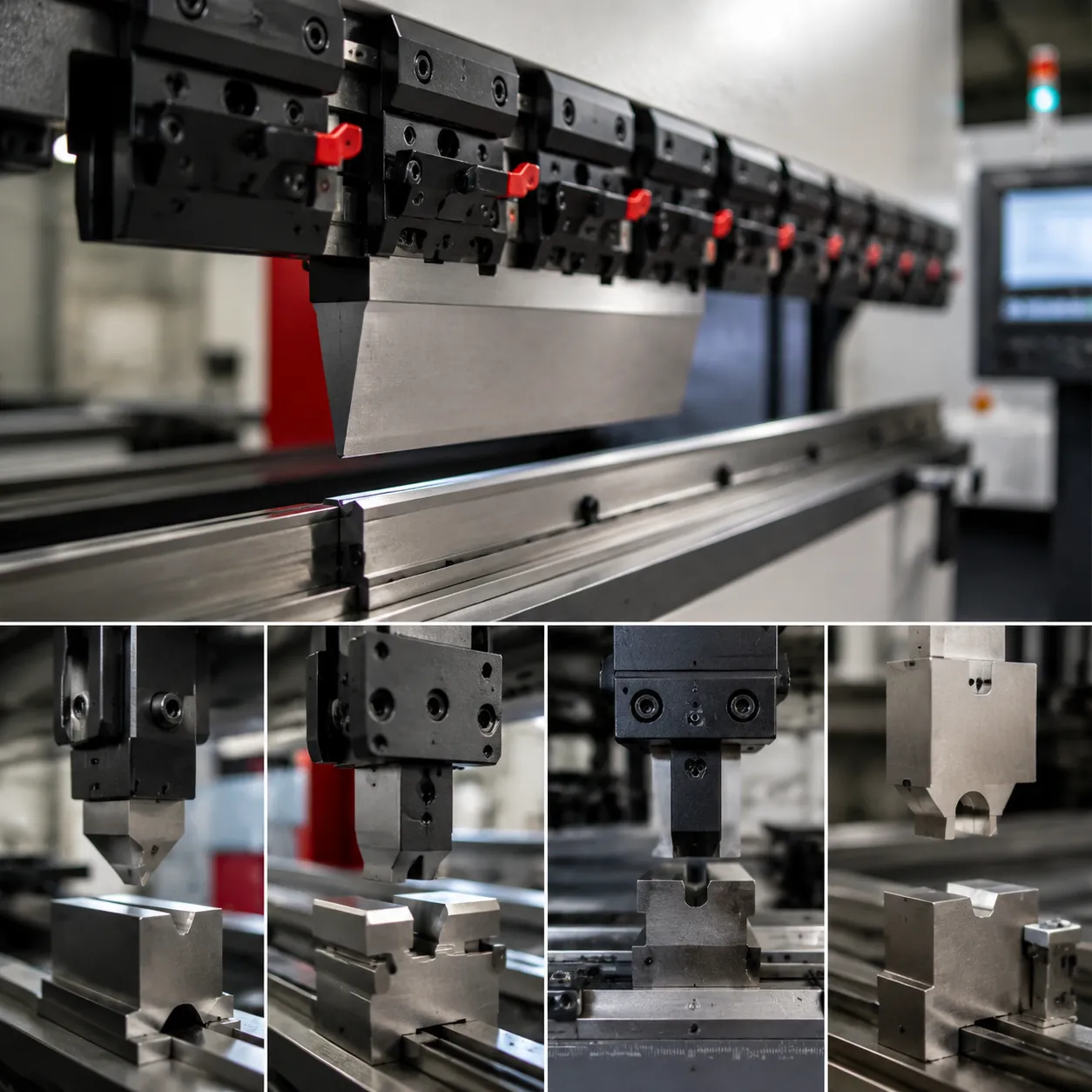
Before executing a press brake die replacement, we verify the exact mounting style and length configuration required for your clamping system. Mismatched tangs or improper seating cause severe ram deflection and inaccurate bend angles.
Mounting Style Identification
We evaluate three primary clamping interfaces to guarantee seamless integration:
- American Precision Style: Features a standard 0.5-inch tang with a safety groove. Ideal for traditional clamping arrangements requiring straightforward manual alignment.
- European / Promecam Style: Utilizes a push-button or manual lever quick-clamping system with a top-tang safety hook. Explore our range of compatible American and European style tooling for exact machine matching.
- New Standard / Wila / Trumpf Style: Uses self-seating hydraulic or pneumatic pin-clamping systems. Delivers automated punch and die alignment for high-precision, rapid tool changes.
Segmented vs. Full-Length Dies
Choosing between solid length bars and segmented press brake tooling depends directly on your part profile and production batch size:
| Feature | Full-Length Solid Dies | Segmented Precision Ground Dies |
|---|---|---|
| Best Application | Long, continuous straight bends | Box forming, four-sided pans, multi-stage setups |
| Handling & Setup | Requires overhead lifts for heavy bars | Fast, single-operator manual loading |
| Flexibility | Fixed bed length | Reconfigurable segments build any target length |
| Accuracy | Standard planing tolerances | Precision ground press brake dies (±0.01 mm accuracy) |
For deep box forming and multi-stage bending, sectionalized bottom dies provide essential clearance for return flanges while preserving uniform height across the entire bed rail.
Standard Operating Procedure: Safe & Precise Die Replacement
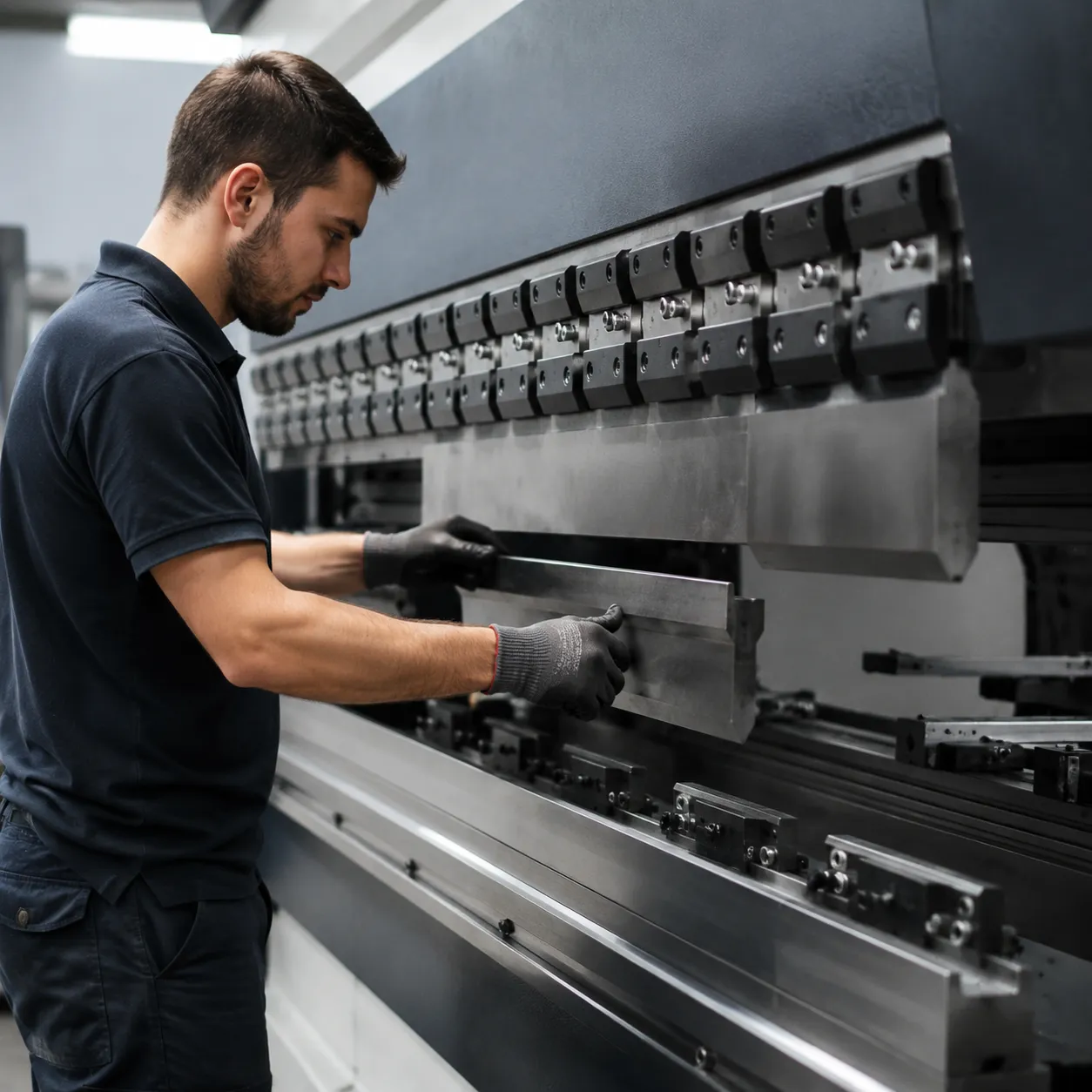
Executing a proper press brake tooling changeover requires a systematic approach to protect shop personnel and maintain tight forming tolerances. Follow our 5-step protocol for every bottom die replacement and setup on your hydraulic press brake tooling system.
Step 1: Pre-Replacement Safety Protocol
- Lockout/Tagout (LOTO): Isolate main electrical power and lock out the main disconnect before reaching into the bend zone.
- Ram Block Placement: Insert mechanical safety support blocks between the upper ram and bed rail to prevent accidental gravity falls.
- Hydraulic Pressure Dump: Vent stored accumulator pressure down to zero PSI and verify that all system pressure gauges read empty. Always review our press brake die rating guide to ensure your setup stays within safe operational limits.
Step 2: Bed Rail Inspection & Cleaning
- Debris Removal: Wipe down the entire lower bed rail with lint-free rags and solvent to remove metal dust, scale, and old oil.
- Oxide & Rust Cleaning: Scour oxidized film using a non-abrasive pad without altering precision ground mating surfaces.
- Burr Checking: Run a hone stone lightly along bed rail shoulders and centerline to eliminate burrs that cause height variations during seating.
Step 3: Installation & Seating
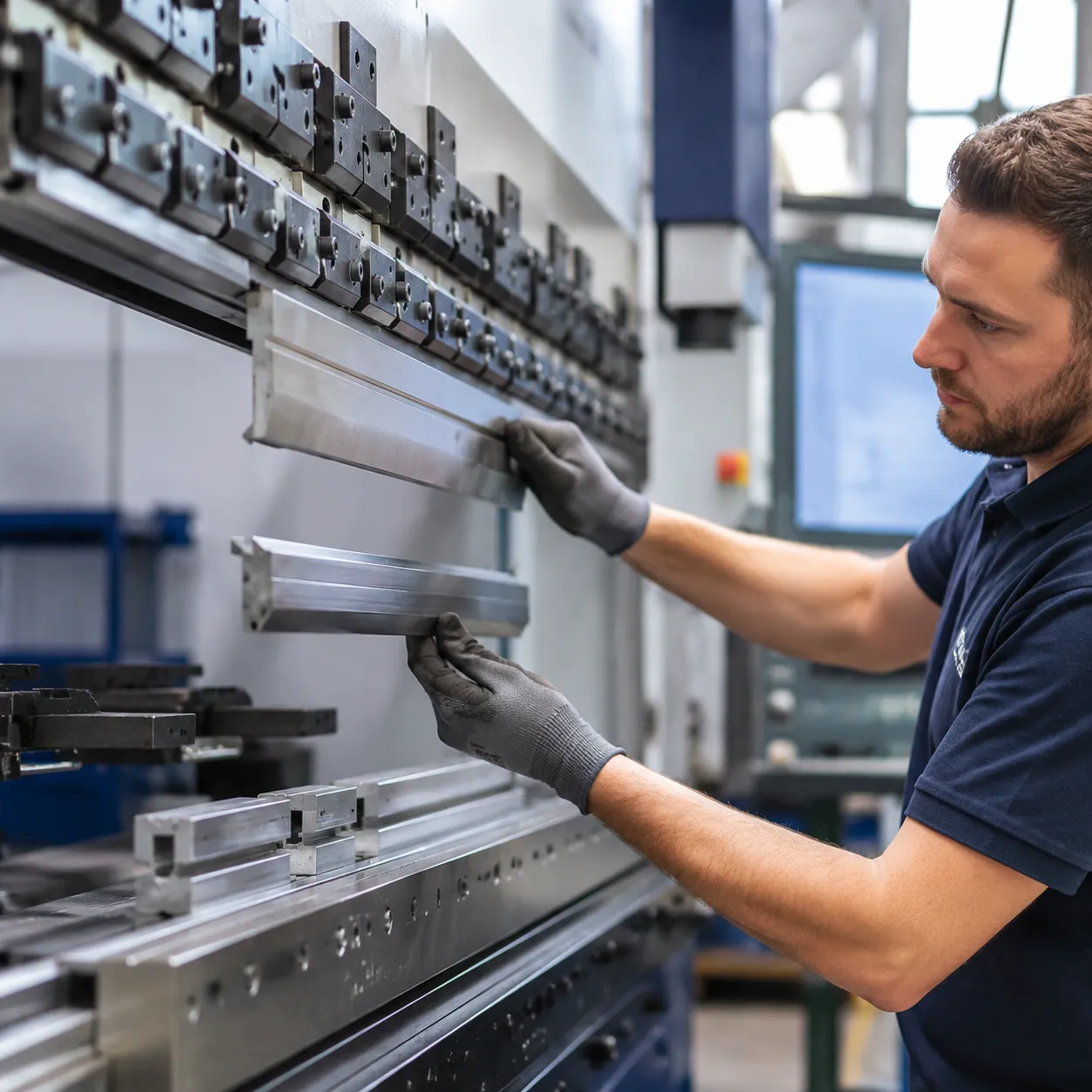
- Load Die Segments: Position segmented press brake tooling onto the lower bed rail from the center outward to balance weight across the ram. Slide a precision-ground female press brake V-die directly into place for smooth seating.
- Pre-Clamping: Engage manual or hydraulic clamps with light pressure to secure segments against the rear locating face while allowing minor adjustments.
- Soft-Seating: Lower the ram under minimal hydraulic pressure to seat the punch tip gently into the V-groove bottom before tightening clamps to final torque specs.
Step 4: Centerline Alignment & Verification
- Visual Verification: Check basic tip-to-groove alignment visually across the full length before applying forming force.
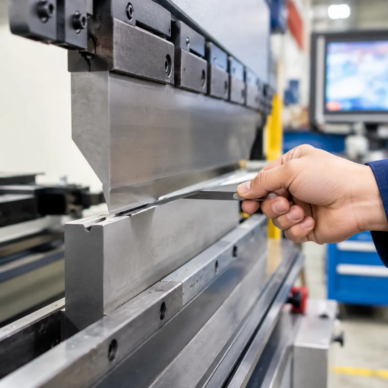
- Punch and Die Alignment: Use a dial indicator or laser alignment tool to measure concentricity between the top punch tip and the bottom V-die shoulder centerline. Maintain alignment within ±0.01 mm along the entire bed length.
Step 5: Test Bending & CMM Validation
- Execute Sample Bends: Run test bends using scrap sheet metal that matches your production material's tensile strength and thickness.
- Optical Angle Validation: Check inside bend angles using an optical protractor or laser angle measurement unit.
- CNC Depth Fine-Tuning: Fine-tune Y1/Y2 axis depth parameters in the CNC control to correct for springback before launching full production runs.
Extending the Working Life of Replacement Tooling
Tonnage Limit Monitoring
Never guess bend loads. Exceeding local tonnage limits causes shoulder radius erosion and permanent deformation.
- Calculate Load Limits: Determine maximum press brake tonnage calculations per foot (or meter) using material tensile strength, sheet thickness, and V-opening width before pressing cycle start.
- Factor Tensile Variations: High-tensile alloys require up to 50% more forming pressure than mild steel. Always calibrate your CNC load parameters accordingly.
- Distribute Bending Forces: Avoid concentrated short-part bending repeatedly in the center of the bed to prevent center-point shoulder wear and ram deflection.
Mar-Free Bending Strategies
Protect polished stainless steel, anodized aluminum, and delicate sheet metal while preserving V-groove entry shoulders.
- Protective Die Film & Inserts: Lay heavy-duty polyurethane film over V-die shoulders to cushion sheet contact and prevent friction galling.
- Mark-Free Tooling Systems: Integrate specialized mark-free bending tooling solutions with rotating shoulder elements to eliminate dragging contact during air bending.
Daily Preventive Maintenance Routine
Daily care prevents premature press brake die wear and maintains tooling centerline alignment shift after shift. Follow established press brake die maintenance practices at every press teardown:
- Clean-Down: Wipe down V-grooves, tangs, and bed rails with solvent and a lint-free shop towel to remove metal scale and grit.
- Anti-Rust Application: Spray a light layer of industrial anti-rust oil over precision-ground working surfaces before storing tools in designated racks.
- Protective Handling: Wear clean, oil-resistant gloves during setup changeovers to prevent skin acids from pitting polished tool steel surfaces.
Precision Replacement Tooling Direct Solutions
When standard off-the-shelf dies fail to deliver, a targeted press brake die replacement strategy backed by direct factory engineering eliminates setup guesswork and keeps production moving. We manufacture high-performance press brake dies designed to integrate seamlessly into your existing workflow without requiring secondary bed adjustments.
Direct Factory Solutions
- Drop-in Compatibility: Custom-engineered replacement dies tailored for major OEM systems and universal clamping setups.
- Plug-and-Play Setup: Precision ground tooling ready for immediate operation, reducing overall changeover time.
- Tailored Geometries: Application-specific precision V-dies built to withstand high-tensile sheet metal and minimize shoulder radius erosion.
Engineering & Simulation Support
- 2D/3D CAD Evaluation: Part drawing analysis to optimize die profile selection and guarantee required bend tolerances.
- 3D Bending Collision Simulation: Virtual trial runs that pinpoint tool, ram, and workpiece interference before metal is formed.
- Springback Analysis: Predictive material calculations that ensure accurate bend angles on the first hit, cutting down scrap rates.
Press Brake Die Replacement FAQs
Identifying Bottom Die Wear Beyond Tolerance
We monitor three key physical indicators on the shop floor to determine when press brake die wear exceeds acceptable limits:
- Angle Drift: Shoulder radius erosion over 0.1 mm causes noticeable angular variation between the center and ends of long sheet metal parts.
- Surface Defect Transfer: Deep pitting, material pick-up, or micro-cracking on V-groove shoulders ruin part cosmetics and alter the floated inside radius.
- Elevated Tonnage Demands: Worn entry shoulders friction-lock the material, forcing hydraulic systems to exert up to 20% more force to reach target bend angles.
When these symptoms crop up, replacing worn components with precision-ground metal forming press brake dies restores tight tolerances and protects your press brake ram from premature wear.
Rule of Thumb for Proper V-Die Selection
Applying the correct V-die selection rule ensures accurate air bending while managing tonnage load:
- 8x Material Thickness (Standard): The baseline setting for mild steel between 0.8 mm and 6 mm thick (V = 8 × t).
- 6x Material Thickness (Tight Radii): Ideal for thinner sheets requiring smaller inside bend radii, though forming force increases.
- 10x to 12x Material Thickness (High-Tensile Steel): Spreads forming tonnage across a wider opening to prevent surface cracking on high-strength metals and heavy plate.
Mixing Segmented Dies with Full-Length Tooling
We strongly advise against placing new segmented press brake tooling alongside worn, full-length tooling bars. Height discrepancies exceeding ±0.01 mm create localized stress points, cause erratic bend angles across your workpiece, and risk damaging the press brake bed rail under load. Always install uniform, precision-ground tooling across the full active bending zone.