
Formula details
Product Details
Overview
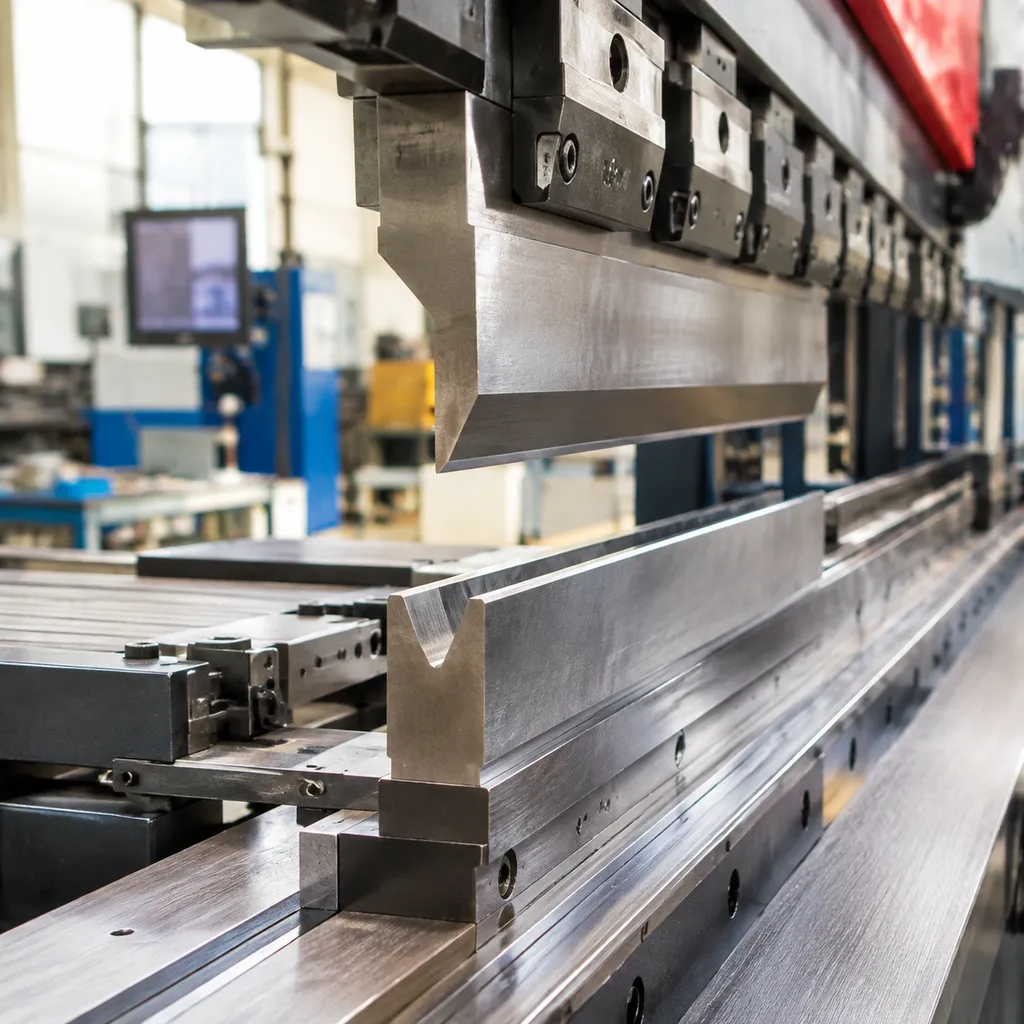
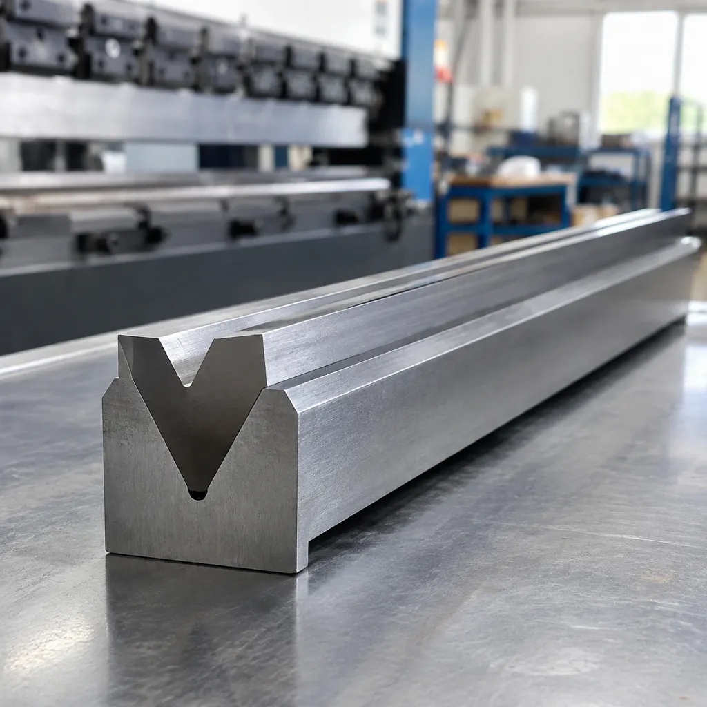
Product Specifications for Press Brake Bottom Die 3.5
Choosing the right press brake bottom die 3.5 requires immediate clarification between two distinct tooling classes: a 3.5 mm micro-V opening for ultra-thin precision sheet metal, and a 3.5-inch (88.9 mm) heavy-duty V opening designed for thick structural plate. We manufacture both configurations to strict dimensional standards, ensuring clean bend lines and predictable springback compensation across all standard press brake open heights.
Technical Data Overview
| Specification | 3.5 mm Micro-V Die | 3.5 Inch Heavy-Duty Plate Die |
|---|---|---|
| V-Opening Width | 3.5 mm (0.138") | 3.500" (88.9 mm) |
| Typical Sheet Range | 0.4 mm – 0.6 mm (0.015" – 0.024") | 11 mm – 14 mm (0.437" – 0.550") |
| Available Angles | 30°, 60°, 85°, 88°, 90° | 60°, 80°, 85°, 88°, 90° |
| Shoulder Radius (R) | R 0.5 mm – R 0.8 mm | R 8.0 mm – R 10.0 mm |
| Standard Base Width | 14 mm – 26 mm | 90 mm – 130 mm |
| Working Heights | 55 mm, 80 mm, 100 mm | 80 mm, 120 mm, 160 mm |
V-Opening Selection: 3.5 mm vs. 3.5 Inch
- 3.5 mm Micro-V Profile: Built for thin-gauge electronic enclosures, precision instruments, and tight-tolerance medical components. Paired with fine-radius punches to eliminate blow-out and minimize minimum flange leg lengths.
- 3.5-Inch (88.9 mm) Plate Profile: Built for high-tonnage structural plate bending, transport manufacturing, and heavy weld preparation. Features expanded trough clearance to prevent material pinch during deep air-bending cycles.
Die Angle Geometry and Springback Control
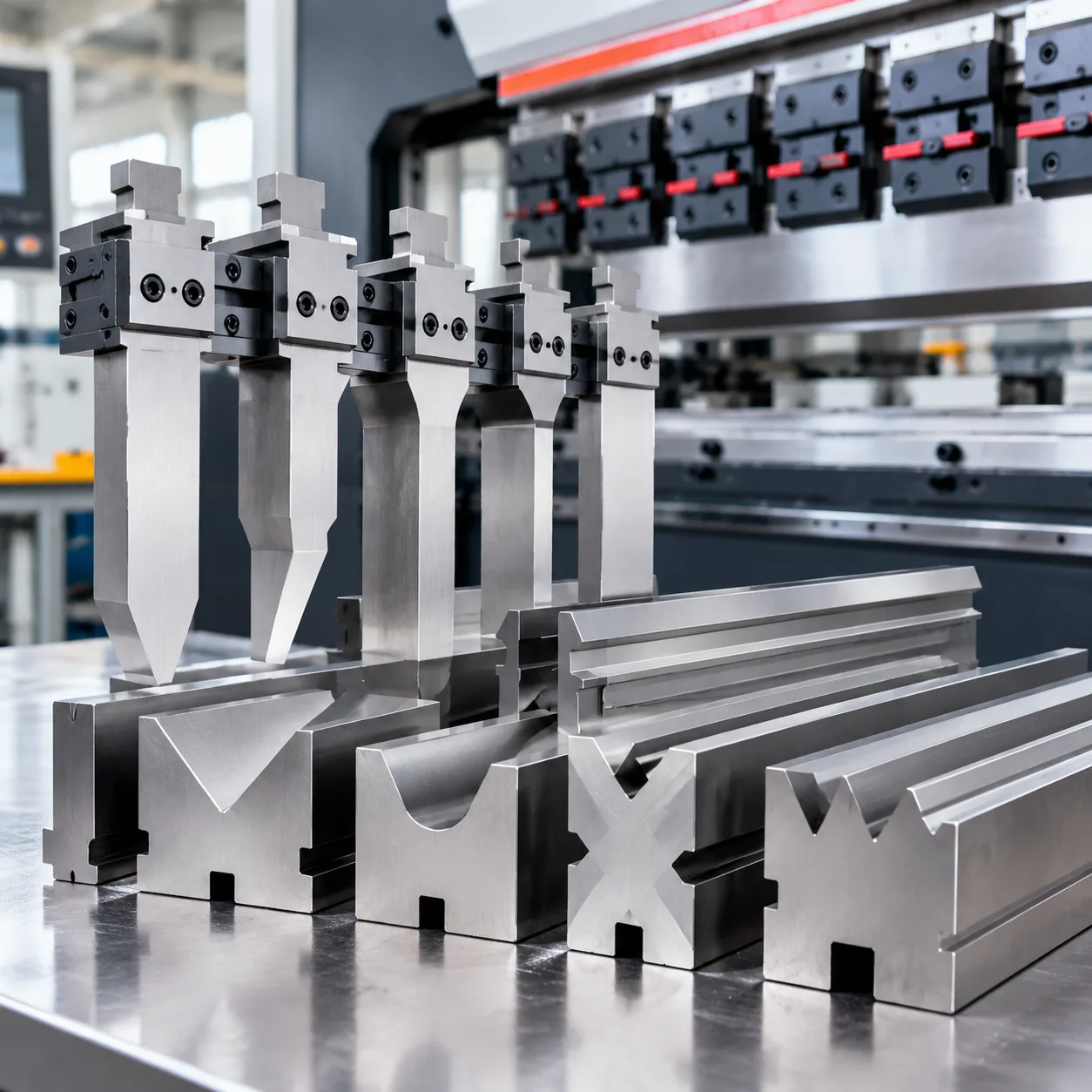
We grind our press brake bottom die 3.5 tooling in five standard included angles to cover all air bending, bottoming, and coining strategies:
30° & 60° Acute Profiles: Optimized for severe springback compensation in high-yield materials, stainless steels, and pre-hemming sequences.
85° & 88° Relief Profiles: Designed for standard air bending in mild steel and aluminum, directly compensating for 2° to 5° of material springback to produce a clean 90° finished part.
90° Square Profiles: Dedicated to bottoming and precision coining operations on light-gauge materials.
Ground Shoulder Radii and Dimensional Envelope
Every bottom die features CNC-ground shoulder entry radii polished to a mirror finish. This precision profile reduces frictional drag, limits tool marks, and prevents material pick-up or gouging on sensitive sheets. Working heights and base footprints align with standard global press brake daylight systems, making drop-in installation seamless across mechanical, hydraulic, and electric machines without requiring specialized riser blocks.
Material Engineering and Hardening Standards for Press Brake Bottom Die 3.5
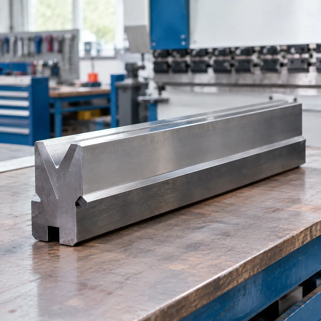
Metallurgical Specs and Grinding Tolerances
- Forged 42CrMo Alloy Core: We machine all dies from solid, hot-forged 42CrMo alloy billets. This material offers superior structural density and fatigue resistance, preventing the die from snapping under sudden pressure spikes. Using proven press brake die steel ensures consistent grain flow across the entire length of the tool.
- Through-Hardened Body (28–32 HRC): The structural base undergoes precision thermal treatment to achieve a uniform core hardness of 28 to 32 HRC. This level of ductility absorbs heavy tonnage without permanent deflection or bed-bowing distortion.
- Induction-Hardened V-Shoulders (52–56 HRC): The radius entry shoulders face continuous friction during air bending. We apply localized high-frequency induction hardening to bring these working surfaces to 52–56 HRC at a depth of 2 to 3 mm. This prevents shoulder galling and grooving when running heavy-scale hot-rolled plate.
- Precision CNC Surface Grinding (±0.01 mm / ±0.0004"): All critical working faces, mounting tangs, and V-grooves are finish-ground to a strict tolerance within ±0.01 mm (±0.0004"). This exact centerline alignment allows seamless modular sectionalizing without angle deviations between adjacent die segments.
Machine Mount and Tang Compatibility
We build each press brake bottom die 3.5 to drop directly into your existing lower beam or die rail without custom fitting or shimming. Whether running tight micro-bends or high-load plate forming, tooling stability depends on the correct mount style. If you are verifying your bed spacing or beam profile, check our press brake die size chart and dimensions guide before securing your lower tool order.
Mount Configurations and Tang Profiles
- European and Promecam Style: Designed with standard 12.7 mm or 13 mm tangs featuring precision safety grooves. These secure cleanly into self-centering lower mechanical holders and prevent tool lift during acute bending.
- American Traditional Configuration: Machined with a 0.500" (12.7 mm) wide single-shoulder tang for direct fitment into conventional manual set-screw rails and heavy-duty die tables.
- New Standard (Wila / Trumpf Style): Features CNC-ground base shoulders with integrated safety pins or pneumatic clamping pins for quick drop-in setup, automated self-seating, and rapid front-loading.
Machine Cross-Compatibility
Our press brake bottom die 3.5 profiles match standard lower beam arrangements across major press brake platforms:
| Press Brake Manufacturer | Supported Mount Types | Clamping System Style |
|---|---|---|
| Amada | European / Promecam Style | Mechanical set screw & auto-centering rails |
| Accurpress | American Traditional | Standard 0.500" slotted die holders |
| Bystronic | New Standard / Bystronic Style | Hydraulic & mechanical high-precision clamps |
| Cincinnati | American Traditional | Bolted lower beds and single-tongue rails |
| LVD | Wila-Trumpf / Promecam Style | Hydraulic wedge and mechanical safety-groove rails |
Bending Tonnage and Sheet Thickness Guidelines
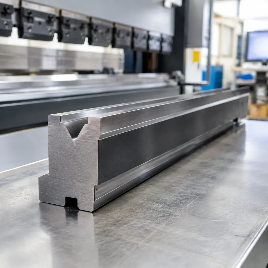
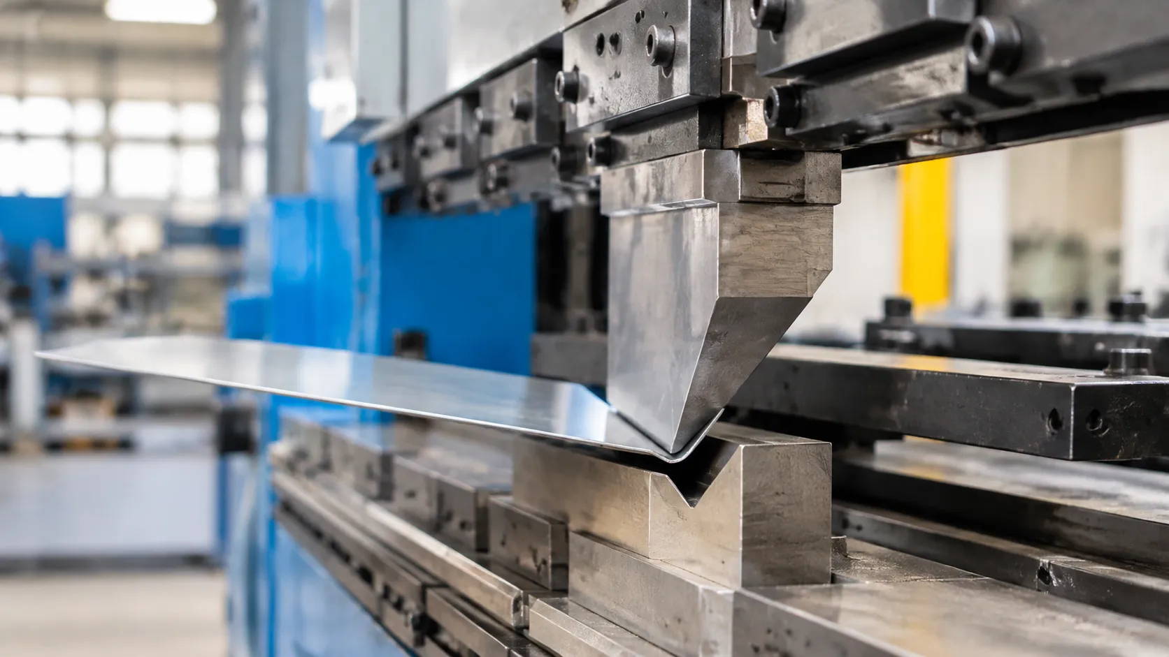
Selecting the correct material gauge for your press brake bottom die 3.5 depends entirely on whether your setup runs a 3.5 mm micro-opening or a 3.5-inch heavy-plate V-die. We follow the standard 6x to 8x material thickness rule (V = 6 to 8 × T) to ensure predictable bend angles, minimal springback, and long tool life.
- 3.5 mm V-Opening: Engineered for precision electronics and light-gauge components. Ideal for material thicknesses between 0.4 mm and 0.6 mm (24 ga to 28 ga).
- 3.5-Inch (88.9 mm) V-Opening: Engineered for structural plate fabrication. Ideal for material thicknesses between 11 mm and 14 mm (7/16" to 1/2" plate).
Minimum Return Flange Calculation
To prevent the sheet from slipping into the die pocket before plastic deformation begins, maintain a safe minimum flange length (b_min). We calculate the minimum flange width using the standard formula:
b_min ≈ 0.7 × V
- 3.5 mm Die: Requires a minimum flange of 2.5 mm (0.098").
- 3.5-inch Die: Requires a minimum flange of 2.45 inches (62.2 mm).
Attempting to bend flanges shorter than these thresholds causes edge drop, uneven leg lengths, and dangerous sheet draw down into the V-groove.
Tonnage-per-Meter Reference
Exceeding the rated load will split the die core or permanently deform the machine beam. When sizing jobs for standard setups or pairing tools with our 50-ton press brake die kit for steel bending, use the tonnage-per-meter values below as a standard operating baseline:
| Material Type | Tensile Strength (σᵦ) | 3.5 mm V-Die (0.5 mm Sheet) | 3.5″ V-Die (12 mm Plate) |
|---|---|---|---|
| Aluminum (5052-H32) | ~210 MPa | 3–4 Tons/m | 38–45 Tons/m |
| Mild Steel (A36 / Q235) | ~450 MPa | 6–8 Tons/m | 75–85 Tons/m |
| Stainless Steel (304 / 316) | ~700 MPa | 9–12 Tons/m | 115–130 Tons/m |
Note: For hard bottoming or coining operations, multiply the air-bending tonnage values by 3x to 5x. Always verify that your machine’s crowning system and the lower tool's maximum rated capacity (printed directly on our die shoulders) exceed your required load.
Maximum Rated Load and Deflection Protection
Every hydraulic press brake lower die has a fixed shear threshold along the shoulder radii. For high-tensile forming on a press brake bottom die 3.5, concentrated point loads must not exceed:
- 3.5 mm V-die max load rating: 40 Tons/m (solid ground bed contact).
- 3.5-inch V-die max load rating: 160 Tons/m across induction-hardened shoulders.
Operating within these parameters prevents shoulder micro-fractures, side-wall flaring, and localized beam deflections that ruin bend consistency.
Length Configurations and Modular Sectionalizing
We supply the press brake bottom die 3.5 in both continuous solid lengths and precision-matched segmented sets to match your exact bed dimensions and bending profiles. Whether you are running high-speed production runs or complex staged setups alongside acute press brake dies, our modular tooling ensures seamless alignment without step marks between adjacent segments.
Standard Continuous Solid Tooling
For straight, uninterrupted bending across sheet metal panels, we stock standard solid lengths engineered for rapid machine bed loading:
835 mm (32.87 in) – Full-length industry standard for primary bending stations.
500 mm (19.68 in) – Medium-format block for localized high-tonnage runs.
415 mm (16.34 in) – Half-length solid sections for compact beds and split-die setups.
Segmented Die Kits for Box and Pan Forming
When bending closed boxes, deep enclosures, or parts with pre-bent return flanges, segmented tooling kits eliminate flange collisions. Each segmented press brake lower die is ground as a matched set to keep shoulder heights uniform within ±0.01 mm across the entire length.
- Left and Right Horns (Ears): 100 mm relieved ends provide side clearance for returned vertical edges.
- Intermediate Segments: Precision-cut sections in 10, 15, 20, 40, 50, 100, 200, and 300 mm widths.
- Full Center Blocks: Standard straight segments to build out any required bend length up to the full press brake capacity.
Custom Continuous Runs for Tandem Press Brakes
For heavy-duty applications requiring a 3.5-inch press brake V die on large hydraulic machines, we manufacture custom-matched continuous runs. Built to order for tandem, trio, or extra-long bed installations, these tools are precision-end-machined so you can interlock multiple sections over lengths exceeding 6 meters without mismatch or deflection steps.
Tool Setup, Surface Protection, and Maintenance
Eliminating Tool Marks with Protective Film
Bending cosmetic materials like mirror-finish stainless steel, pre-painted sheets, or architectural aluminum causes friction marks across the die shoulders.
- Urethane Protective Tape: Apply high-density polyurethane protective film directly over the shoulders of your press brake lower die.
- Compensation for Thickness: The film acts as a buffer between the sheet and the hardened steel. Account for film thickness (typically 0.4 mm to 0.8 mm) in your CNC depth settings to maintain precise bend angles.
- Tensioned Holders: For production runs, secure the urethane film with magnetic tensioning brackets to keep the material smooth and wrinkle-free across the entire bed length.
Seating and Centering on the Lower Beam
Proper alignment prevents uneven side loads that can split the die or damage the ram guide system:
- Clean the Bed and Tang: Wipe the press brake bed, die holder rail, and the tang of the press brake bottom die 3.5 clean of slag, chips, and dried oil before drop-in.
- Light Clamping: Drop the die into the holder and hand-tighten or lightly engage the clamping bars.
- Center Under Low Tonnage: Lower the punch tip into the center of the V-groove under minimal hydraulic pressure (inching mode) to seat and self-center the tool along the entire centerline.
- Full Lock-Down: Tighten the mechanical set-screws or engage hydraulic clamping from the center outward to ensure uniform seating across the machine bed.
Inspection: Galling, Edge Rolling, and Fatigue
Routine checks catch tooling wear before it causes out-of-spec parts:
- Shoulder Galling: Check for material transfer along the die radiuses, especially when running galvanized steel or heavy aluminum. Stone the edges lightly to remove pick-up without altering the shoulder radius. When shoulder wear becomes excessive, professional press brake die resurfacing services restore the original profile and critical tolerances.
- Edge Rolling: Inspect the V-shoulders for rounding or localized depression caused by exceeding the maximum tonnage rating.
- Micro-Cracking: Perform magnetic particle inspection or liquid penetrant testing along the root radius of high-tonnage 3.5-inch dies to detect fatigue stress cracks early.
Storage and Corrosion Protection
Alloy tool steels like 42CrMo require dry, stable storage to prevent rust and edge degradation:
- Wipe Down and Oil: Clean off shop dust, coolants, and scale after every job. Apply a thin coat of rust-inhibiting oil or light machine lubricant across all ground working faces.
- Dedicated Racks: Store sectionalized tools and solid lengths vertically or in padded horizontal tooling cabinets with composite dividers. Never stack bare bottom dies directly on top of each other.
- Marking Retention: Keep etched tonnage limits, V-opening dimensions, and segment widths visible to avoid tooling mismatches during future setups.
Frequently Asked Questions About Press Brake Bottom Die 3.5
How do I know if I need a 3.5 mm or 3.5-inch V-opening for my project?
Material thickness determines your V-opening choice. A 3.5 mm V-opening is engineered for micro-bending thin electronic enclosures and precision components (typically 0.4 mm to 0.6 mm material). A 3.5-inch (88.9 mm) V-opening handles heavy-duty structural plate between 3/8" (9.5 mm) and 1/2" (12.7 mm). If your blueprint calls for micro-flanges on ultra-thin sheet, select 3.5 mm; if you are processing structural steel or heavy plate, select the 3.5-inch configuration.
What maximum sheet metal thickness can I run safely over a 3.5 bottom die?
We recommend adhering to the standard 8x material thickness rule for reliable air bending:
3.5 mm V-Die: Maximum safe thickness is 0.5 mm to 0.6 mm (24–26 gauge) mild steel. Running thicker material risks die cracking and shoulder galling due to extreme tonnage concentration.
3.5-Inch V-Die: Maximum safe plate thickness is 7/16" (11 mm) mild steel or 3/8" (9.5 mm) high-tensile material. Running 1/2" plate requires monitoring maximum tonnage ratings to prevent die deflection or splitting.
Will this 3.5 bottom die fit an Amada-style or Promecam-style die rail?
Yes. Our tooling options include standard 12.7 mm and 13 mm tangs with safety retainers designed to seat directly into standard European, Amada, and Promecam lower tool holders. If your brake features an American-style slotted bed, we supply offset or centered tangs built specifically for those rails. Review our guide on press brake die replacement for American and European styles to match your machine’s clamping system and center-line offset.
Can I perform both air bending and bottoming operations with this die profile?
Our press brake bottom die 3.5 profiles are optimized for air bending. Air bending allows you to form multiple angles (from 30° to 90°) simply by adjusting stroke depth, keeping tonnage low and prolonging tool life. While you can bottom bend thin materials in 88° or 90° dies, bottoming increases required tonnage by 4x to 6x. Bottoming thick plate on a 3.5-inch opening risks exceeding press capacity and permanently deforming the die shoulders. For consistent angular accuracy at lower press loads, paired air bending tooling like our swag air bending bottom die compatible press brake line delivers optimal results without excessive machine wear.
How can I prevent marking polished aluminum or stainless steel using this die?
To prevent tool marks and die shoulder pick-up on cosmetic materials:
Apply protective film: Lay high-density polyurethane die cover film across the V-opening shoulders before bending.
Maintain clean shoulders: Wipe the hardened contact radii regularly to remove mill scale flakes, metal dust, and burrs.
Check shoulder radius condition: Ensure the lead-in radius is smooth and polished; stone out any burrs or galling immediately to maintain scratch-free finishes.