
Identifying Tool Wear: When Does a Die Need Resurfacing?
Visual Wear Signs: Shoulder Galling, Scoring, and Punch Nose Deformation
Physical inspection under good lighting reveals the earliest signs of tool degradation:
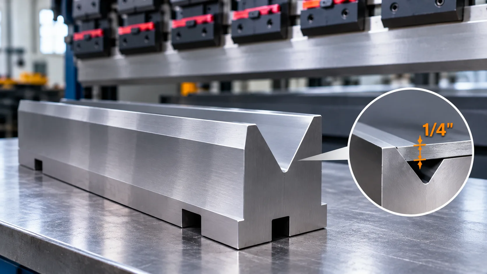
- V-Die Shoulder Galling & Pitting: Material pickup—especially when forming galvanized, stainless, or aluminum sheet—creates rough spots along the V-die entry radii.
- Longitudinal Scoring: Deep grooves cut into the shoulder radii alter friction dynamics, accelerating localized wear.
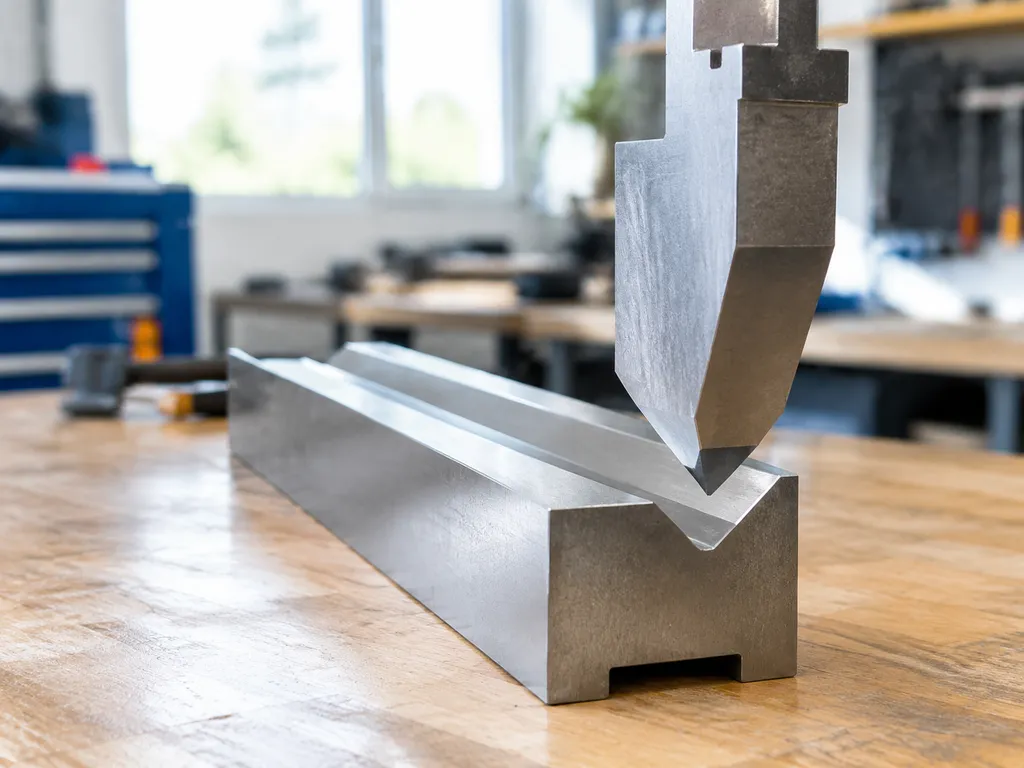
- Punch Nose Flattening or Chipping: High-tonnage bottoming or air-bending thick plate crushes the punch tip radius, creating asymmetrical contact profiles.
Dimensional Errors: Flange Angle Variation and Inconsistent Springback
When tool geometry shifts, bend angle consistency collapses across the bed:
- Crown & Center Deflection: Heavy center wear leads to "canoe-shaped" bends, where parts are over-bent at the ends and under-bent in the center.
- Wear Tolerance Thresholds: If shoulder radius wear exceeds 0.1 mm (0.004”) or punch tip asymmetry exceeds 0.08 mm (0.003”), standard CNC crowning can no longer compensate.
- Unpredictable Springback: Uneven shoulder friction causes erratic sheet draw into the V-opening, making repeatable springback compensation impossible.
Operational Red Flags: Sudden Tonnage Spikes and Sheet Marking
| Symptom | Direct Mechanical Cause | Action Limit |
|---|---|---|
| Increased Bending Tonnage | Degraded shoulder radii create higher friction resistance as the sheet enters the die. | 10%–15% increase over baseline tonnage calculation |
| Severe Part Surface Marking | Galled shoulders and scored punch tips gouge the exterior face of cosmetic materials. | Visible transfer marks on pre-painted or stainless sheet |
| Segment Alignment Failure | Uneven wear across segmented tooling sets causes stepped lines along long bend lengths. | Height differential over 0.02 mm (0.0008”) between adjacent tools |
Hardness Depth Wear Rule: Checking Remaining Case Depth
Before scheduling press brake tooling reconditioning, verify that the remaining hardened layer is sufficient to support bending forces:
- Through-Hardened Tooling (50–55 HRC throughout): Can be reground multiple times across its lifespan, limited only by structural integrity, minimum working height, and tonnage derating.
- Induction or Laser-Hardened Tooling (56–60 HRC surface): Hardness is concentrated in a case depth typically ranging from 1.5 mm to 3.0 mm (0.060” to 0.120”).
- The Regrind Limit Rule: Total material removed over the lifespan of induction-hardened tooling must not exceed 50% of the original case depth. Grinding beyond this boundary exposes the soft 28–32 HRC core steel, causing rapid, permanent plastic deformation under normal operating loads. Ultrasonic hardness testing or micro-indentation checks confirm adequate case depth prior to resurfacing.
The Technical Process of Press Brake Die Resurfacing
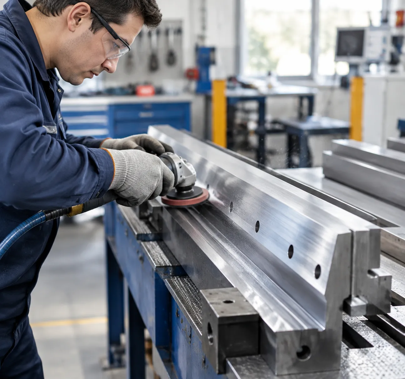
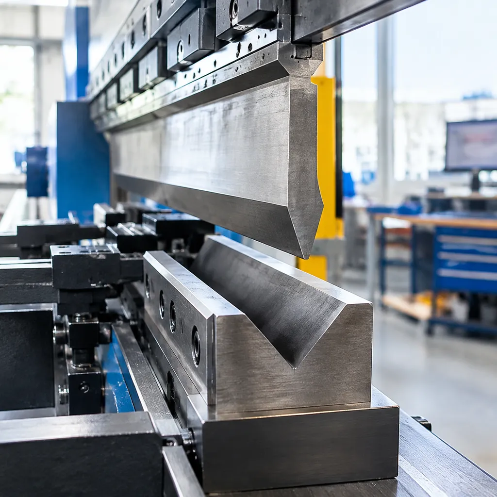
Restoring worn tooling requires micrometer-level precision. When we execute press brake die resurfacing, we follow a strict six-step remanufacturing workflow that brings worn punches and V-dies back to factory tolerances while preserving structural integrity.
Step 1: Metrological Inspection, CMM Profile Scanning, and Hardness Testing
Every reconditioning project starts with non-destructive diagnostics:
3D CMM Profile Scanning: Maps tool wear patterns, localized deformation, and twist along the entire length of the tool.
Hardness Depth Verification: Ultrasonic and eddy-current testing confirms that sufficient effective case depth remains (typically requiring at least 1.0 mm to 1.5 mm of hardened layer post-grind) before material removal begins.
Magnetic Particle Inspection (MPI): Detects hidden micro-cracks at the punch nose and V-die bottom radius.
Step 2: Precision CNC Profile Grinding
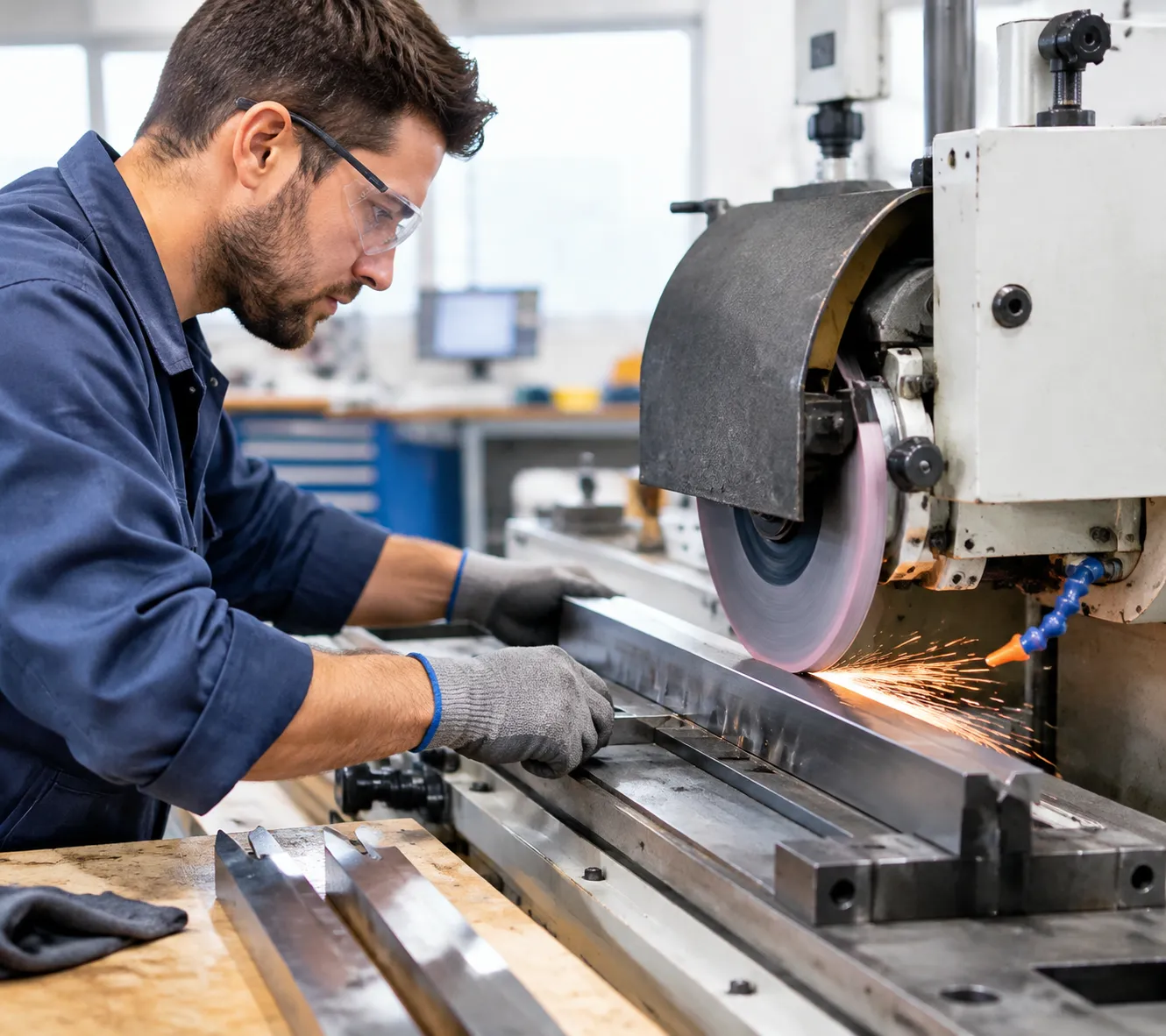
We use high-rigidity CNC surface and profile grinders equipped with cubic boron nitride (CBN) wheels to restore punch tips, V-groove flanks, and relief angles:
Coolant Management: High-pressure, temperature-controlled flood coolant prevents thermal stresses, burning, and annealing of the hardened tool steel.
Uniform Stock Removal: Grinding passes are limited to light, controlled depths (0.005 mm to 0.015 mm per pass) to avoid inducing residual tensile stresses.
Step 3: Maintaining Tooling Centerline Alignment and Shoulder Radius Geometry
Maintaining strict tooling centerline alignment relative to the mounting tang is non-negotiable. If the centerline shifts during regrinding, it causes off-center loading, uneven backgauge offsets, and asymmetric bend angles:
V-Die Shoulder Radius Restoration: We CNC-grind matching radii on both die shoulders to eliminate galling edges and ensure uniform sheet intake.
Symmetry Control: Flank angles and shoulder heights are ground strictly symmetrical to the primary tool centerline within ±0.005 mm.
Step 4: Sectional Tool Matching
Segmented punches and dies must operate interchangeably in staged setups. We grind entire segmented tool sets in matched fixtures during a single continuous setup:
Height Matching: Working height variation across individual segments is held within ±0.01 mm (±0.0004”).
Interchangeability: Guarantees that operators can swap, reorder, or combine sections along the bed without shimming.
Step 5: Micro-Finishing and Polishing
Tool surface condition directly affects sheet friction and part cosmetic quality:
Surface Roughness Reduction: We polish contact surfaces from standard ground finishes down to Ra 0.2–0.4 µm (8–16 µin).
Material Pickup Prevention: Micro-finishing removes directional grinding marks that trap galvanized flaking, mill scale, or aluminum pickup.
Step 6: Post-Grind QA, Dimensional Validation, and Load Testing
Before returning tools to production, we verify all critical geometry against standard press brake die size chart and dimensions specifications:
Optical Profile Comparator: Validates punch tip radius, V-groove angle, and relief clearances.
Laser Bed Verification: Confirms straightness and parallelism over the entire length.
Sample Test Bending: Sample test bends confirm angle consistency across both ends and the center under working tonnage.
Press Brake Tooling Resurfacing Process Standards
| Process Step | Primary Target Parameter | Standard Tolerance / Specification |
|---|---|---|
| Inspection | Case depth & crack detection | Minimum remaining case depth: 1.0 mm |
| Profile Grinding | V-angle & tip geometry | Angle accuracy: ±15 arcminutes (±0.25°) |
| Centerline Alignment | Tang-to-V-groove center | Symmetrical alignment: ±0.005 mm (±0.0002”) |
| Sectional Matching | Working height across segments | Uniformity: ±0.01 mm (±0.0004”) |
| Micro-Finishing | Shoulder & flank surface finish | Surface roughness: Ra 0.2 to 0.4 µm |
| Final QA | Bend angle consistency | Angular variation: < 0.5° across full length |
Critical Engineering Constraints in Press Brake Die Resurfacing
Hardness Depth Limits: Through-Hardened vs. Surface-Treated Tools
Every tool steel composition and heat-treatment method dictates how much material we can safely remove during press brake die resurfacing:
- Through-Hardened Tooling (e.g., 42CrMo, 1.2312): Features uniform hardness (typically 48–52 HRC) throughout the entire body. These tools allow multiple regrinds across their lifespan without losing wear resistance. Check our press brake tooling material guide to evaluate specific base alloy capabilities.
- Induction & Laser-Hardened Tooling: Delivers extreme hardness (56–60 HRC) concentrated only at the working zones (the punch tip and V-die shoulder radii). The hardened case depth typically ranges from 1.5 mm to 3.0 mm (0.060"–0.120").
| Tooling Hardness Type | Typical Surface Hardness | Effective Case Depth | Maximum Safe Grind Stock |
|---|---|---|---|
| Through-Hardened | 48 – 52 HRC | 100% Core Depth | Up to 1.50 mm (0.060") per side |
| Laser-Hardened | 56 – 60 HRC | 1.50 – 2.00 mm | 0.30 – 0.50 mm (0.012"–0.020") total |
| Induction-Hardened | 58 – 62 HRC | 2.50 – 3.50 mm | 0.50 – 0.80 mm (0.020"–0.031") total |
The Risk of Grinding Past Effective Case Depth
Grinding through the hardened layer exposes the softer structural base steel (28–32 HRC). When a tool runs past its case depth limit:
- Immediate Plastic Deformation: Softened V-die shoulders crush under baseline air-bending forces.
- Severe Galling and Pickup: Unhardened steel rapidly galls when bending stainless steel or high-strength sheet.
- Irreversible Pitch Deviations: Bending angles drift uncontrollably along the bend line within hours of installation.
[ Hardened Zone: 58-62 HRC (1.5 - 3.0 mm) ] <-- Resurfacing MUST stay within this layer
[ Soft Base Steel Core: 28-32 HRC ] <-- Exposing this causes immediate tool failure
Working Height Reduction and CNC Crowning Adjustments
Material removal permanently alters the tool’s critical dimensions. When executing a press brake tooling reconditioning plan, we track these shifts directly on the press brake controller:
- Working Height Offsets: Removing 0.25 mm (0.010") from a punch tip or die base requires recalibrating the machine’s Y1/Y2 axis zero-points to avoid under-bending.
- Crowning Profile Shifts: Uneven wear across the bed length often requires grinding the center more than the ends. The CNC crowning system must be recalibrated with a fresh baseline curve to prevent canoeing (over-bending the center relative to the edges).
- Segmented Tool Matching: If regrinding a partial section of a modular tool set, the entire segmented line must be ground in a single setup to maintain a strict working height tolerance within ±0.01 mm (±0.0004").
Bending Tonnage Derating After Material Removal
Sharpening punches and remachining V-openings removes load-bearing metal from the tool geometry. After resurfacing:
- Punch Tips: Reducing the punch nose radius or thinning the neck increases localized stress concentration, lowering the rated tons-per-meter threshold.
- V-Die Shoulders: Grinding worn die shoulders increases the effective V-width slightly unless the relief angles and base seats are recut.
- Derating Factor: A general engineering rule is to derate maximum allowable tonnage by 5% to 10% for every 0.5 mm (0.020") of cross-sectional tool mass removed. Never run resurfaced tooling at the original OEM maximum tonnage rating without recalculating your yield parameters.
Economic Analysis: Press Brake Die Resurfacing vs. Tool Replacement
Deciding whether to recondition or buy new comes down to remaining case depth, lead times, and total cost of ownership (TCO). In our shop floor evaluations, precision press brake die resurfacing consistently delivers identical bending accuracy at a fraction of the cost of purchasing new OEM tooling.
Direct Cost and Lead Time Comparison
- Cost Savings: Precision regrinding typically costs 20% to 40% of a new tool’s purchase price. For high-end segmented or precision-ground European and American style tooling, this translates directly to thousands of dollars saved per tool set.
- Turnaround Speed: Turnaround for a professional die grinding and polishing service is typically 2 to 5 shop days, avoiding the extended 4 to 12 week OEM backorders that disrupt production schedules.
- Total Cost of Ownership (TCO): Running a tool through two or three resurfacing cycles slashes your cost-per-bend over the tooling lifecycle by more than 50%, maximizing the return on your initial steel investment.
| Decision Metric | Press Brake Die Resurfacing | New Tooling Purchase |
|---|---|---|
| Direct Expense | 20% – 40% of original list price | 100% full retail expenditure |
| Average Lead Time | 2 – 5 days turnaround | 2 – 10+ weeks for OEM delivery |
| Hardness Retention | Maintained within active case depth | Full factory case depth |
| Working Height | Adjusted by 0.2 mm – 0.8 mm | Factory standard baseline |
| Lifecycle ROI | Maximizes initial tool steel asset value | Resets tooling capital cycle |
Clear Retirement Thresholds: When to Scrap the Die
Resurfacing is an effective maintenance strategy, but running a tool past its engineering limits leads to part rejection and potential machine damage. We scrap and replace tooling when it meets any of the following criteria:
- Case Hardening Depletion: The usable induction-hardened or laser-hardened depth (typically 58–60 HRC) has been ground away, exposing the softer core steel (<45 HRC) that deforms rapidly under load.
- Excessive Height Reduction: Total material removal exceeds 1.5 mm (0.060”), surpassing the machine's CNC crowning limits and stroke compensation ranges.
- Structural Fractures: Non-destructive testing (NDT) reveals micro-cracks or deep fractures along the punch tip or V-groove shoulder radius.
- Geometric Limits Exceeded: Grinding to clean up damage would blow out the shoulder radius or V-opening beyond allowable part tolerance limits.
When a die reaches these critical wear thresholds, moving forward with a full press brake die replacement is the only reliable way to protect machine operators and maintain precise bend angle consistency. For standard setups, upgrading directly to hardened precision press brake dies eliminates repeated setup adjustments and keeps production lines running at peak tonnage capacity.
Operational Best Practices to Maximize Resurfaced Tool Life
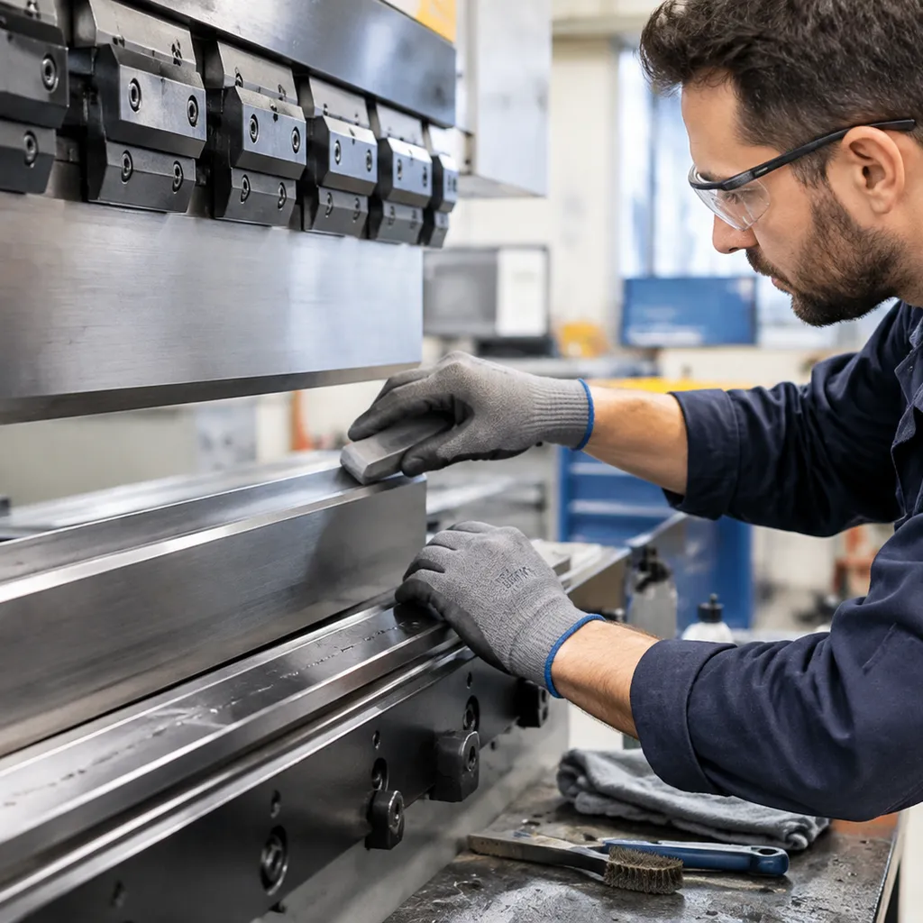
Proper Die Seating, Clamping Alignment, and Zero-Point Calibration
Never drop a resurfaced tool into the holder and immediately apply full working tonnage. Because the overall working height changes slightly during the grinding process, recalibrating your machine's reference points is critical:
- Clean the Bed and Tangs: Wipe down the machine bed, die holders, and tool tangs to eliminate any metal chips or dust larger than 0.005 mm.
- Low-Tonnage Seating: Seat the tooling using a low-pressure clamp cycle (around 5–10% of standard load) to let the self-aligning shoulders find true center before torquing hydraulic or mechanical clamps.
- Recalibrate Zero-Point: Update your CNC controller with the new measured tool heights. Failing to reset zero-point limits can drive punches too deep into resurfaced precision V-dies, causing instant shoulder scoring or tip fracture.
Sheet Surface Prep and Lubrication Strategies
Mill scale, rust, and laser oxide are the primary culprits behind abrasive shoulder wear. Managing material contact directly extends the life of reconditioned surfaces:
- Scale and Oxide Removal: Laser oxide flakes act like sandpaper on polished shoulder radii. Deburr cut edges and wipe down hot-rolled pickled and oiled (HRPO) or stainless blanks before forming.
- Targeted Lubrication: Use high-pressure dry-film lubricants or heavy-duty forming oils on severe galling candidates like galvanized sheet or thick structural steel.
- Protective Urethane Films: Apply non-marking urethane protective film over the die shoulders when bending polished or aluminum parts to eliminate friction-based material pickup.
| Maintenance Factor | Standard Operation | Post-Resurfacing Requirement | Impact on Tool Life |
|---|---|---|---|
| Bed & Tang Cleanliness | Daily sweep | Wipe down prior to every setup (Zero grit tolerance) | Eliminates uneven point-loading |
| Die Seating Pressure | Immediate clamp | Low-pressure seating under 10% load | Prevents centerline misalignment |
| Oxide Management | Unchecked raw plate | Edge deburring and dry-lube application | Reduces shoulder abrasion by up to 50% |
| Tonnage Monitoring | Visual estimate | Explicit derating recalculation per job | Prevents core deformation |
Adhering to Tonnage-Per-Meter Limits to Prevent Core Deformation
Since material was removed during reconditioning, your dies have a thinner effective case depth and slightly modified structural profiles. Exceeding rated limits can permanently crush the core base steel.
- Always consult a dedicated die tonnage safety guide before programming thick-gauge runs.
- Derate your maximum allowable tonnage per meter by 10% to 15% for tools that have undergone multiple resurfacing cycles.
- Distribute small-width, high-tonnage bends across the bed rather than hitting the exact center of segmented tooling every time.
Climate-Controlled Tooling Storage and Handling Procedures
Freshly ground surfaces lack factory protective oxide layers until fully broken in, making them vulnerable to environmental damage:
- Dedicated Tool Cabinets: Store punches and dies in partitioned drawers with protective polyurethane dividers to stop hardened surfaces from knocking against each other.
- Corrosion Protection: Coat ground working surfaces with a light layer of rust-inhibiting fluid before storage, maintaining ambient shop humidity below 50% RH.
- Handling Segments: Never drag segmented tooling across the press brake bed. Always lift and seat sections vertically to preserve the ground end faces and maintain matched sectional tolerances.
Frequently Asked Questions About Press Brake Die Resurfacing
How many times can a press brake die safely undergo resurfacing?
The allowable number of regrinds depends strictly on how the steel was originally hardened:
- Through-hardened tooling (54–60 HRC): Can typically undergo 3 to 6 resurfacing cycles. Because the core maintains uniform hardness, material removal is limited only by minimum structural load limits and maximum allowable working height loss.
- Induction- or laser-hardened tooling (case depth 1.5–3.0 mm): Usually limited to 1 to 2 light regrinds. Grinding past the hardened case into the soft base steel (typically 28–32 HRC) destroys wear resistance and causes immediate shoulder collapse under load.
How do altered die heights impact modern CNC backgauge and angle calculations?
Every pass during precision die grinding reduces the overall working height of the tool. When height changes:
- Y-Axis Depth Calibration: A loss of even 0.2 mm (0.008”) directly changes the pinch point and air-bending penetration depth, causing severe under-bending if uncorrected.
- CNC Tool Library Updates: The new physical height must be re-measured and entered into the CNC controller's tool parameters to recalibrate the zero-point and auto-crowning curves.
- Backgauge (R-Axis) Offsets: Flange height calculations rely on exact die shoulder planes. Re-zeroing the backgauge prevent sheet slippage and collision risks across different press brake die types running on the same bed.
Can damaged, cracked, or severely chipped punch tips be repaired?
Minor surface pitting or shallow chips (under 0.5 mm) can be re-profiled across the entire punch length to restore original radius geometry.
However, dies with deep transverse cracks, stress fractures along the neck, or extensive tip spalling cannot be safely repaired. We do not recommend welding or brazing fractured high-alloy tool steels; welding introduces localized heat-affected zone (HAZ) stresses that drastically increase catastrophic failure risks under high tonnage, especially on slim profiles like acute press brake dies.
What is the ideal surface roughness (Ra) for resurfaced V-die shoulders?
Target surface finishes for precision V-die shoulder radius restoration include:
- Standard Ground Finish: Ra 0.4 to 0.8 µm (16 to 32 µin)—acceptable for standard mild steel bending where minor die lines are permissible.
- Micro-Polished Finish: Ra 0.1 to 0.2 µm (4 to 8 µin)—required for galling-prone materials such as aluminum, prepainted stock, and mirror-finish stainless steel.
Achieving a low Ra finish significantly reduces drag friction, prevents zinc/aluminum pick-up, and maintains predictable springback compensation across extended production runs.