
Core Bending Physics & Engineering Design
Building high-performance tooling requires a thorough understanding of force distribution, sheet metal behavior, and strict geometric calculations. Before machining steel, we calculate exact load limits and material springback to guarantee precision performance without structural failure.
Mechanics of Bending & Tool Loading
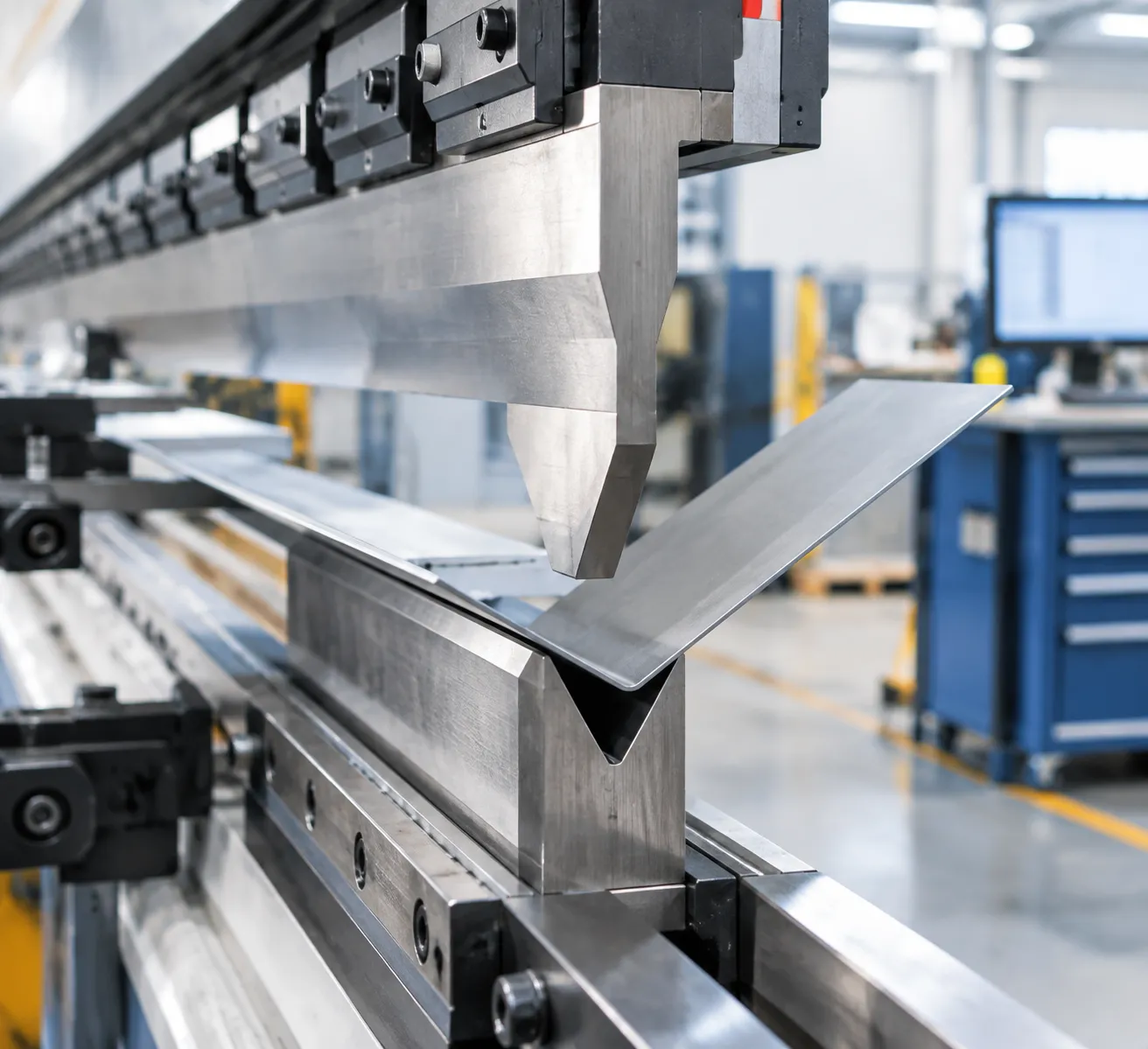
Selecting the right bending process directly dictates force parameters and tool longevity. We analyze three core methods to establish safe loading limits:
| Bending Method | Penetration Mechanics | Tonnage Requirement | Angle Control | Tooling Wear Level |
|---|---|---|---|---|
| Air Bending | Punch contacts material at 3 points without touching the V-bottom | Low (Baseline 1x) | Controlled by stroke depth | Minimal wear |
| Bottoming | Material presses against V-die surfaces with light bottom pressure | Medium (3x to 5x of Air) | Controlled by die V-angle | Moderate wear |
| Coining | High pressure stamps punch tip fully into the sheet metal core | Extreme (8x to 10x of Air) | Fixed by punch and die shape | High wear & damage risk |
To prevent permanent die deformation or catastrophic cracking under high load:
- Tonnage Calculation: Tonnage (Tons/Meter) = (650 × t²) / V for standard mild steel (where t = sheet thickness in mm, V = V-die opening width in mm).
- Air Bending Tonnage Limit: We design dies to operate within 80% of the steel's yield strength, preventing micro-fractures during heavy production cycles.
Engineering Formulas for V-Die Geometry
Accurate V-die opening calculations are critical to achieving precise bend radii and preventing material drag.
| Application Type | Sheet Thickness (t) | Standard V-Die Opening (V) | Expected Inside Radius |
|---|---|---|---|
| Thin Sheet / Tight Radius | t < 1.5 mm | V = 6 × t | ~1.0 × t |
| Standard Mild Steel | 1.5 mm ≤ t ≤ 6 mm | V = 8 × t | ~1.27 × t |
| Heavy Plate Forming | t > 6 mm | V = 10 × t to 12 × t | ~1.5 × t to 2.0 × t |
- Tooling Shoulder Radius Optimization: We set the entry shoulder radius to roughly 1.5 × t. Smooth, polished shoulder radii prevent sheet metal dragging, decrease required tonnage, and eliminate surface scoring on sensitive workpieces.
CAD Modeling & 3D Bending Simulation
When evaluating how to make a press brake die, advanced 3D CAD modeling prevents expensive machining re-runs and tool collisions.
- Sheet Metal K-Factor & Springback: We program exact K-factors (typically 0.33 for air bending, 0.45 for bottoming) into standard 2D and 3D CAD models (DXF, DWG, STEP) to compensate for material springback before cutting stock.
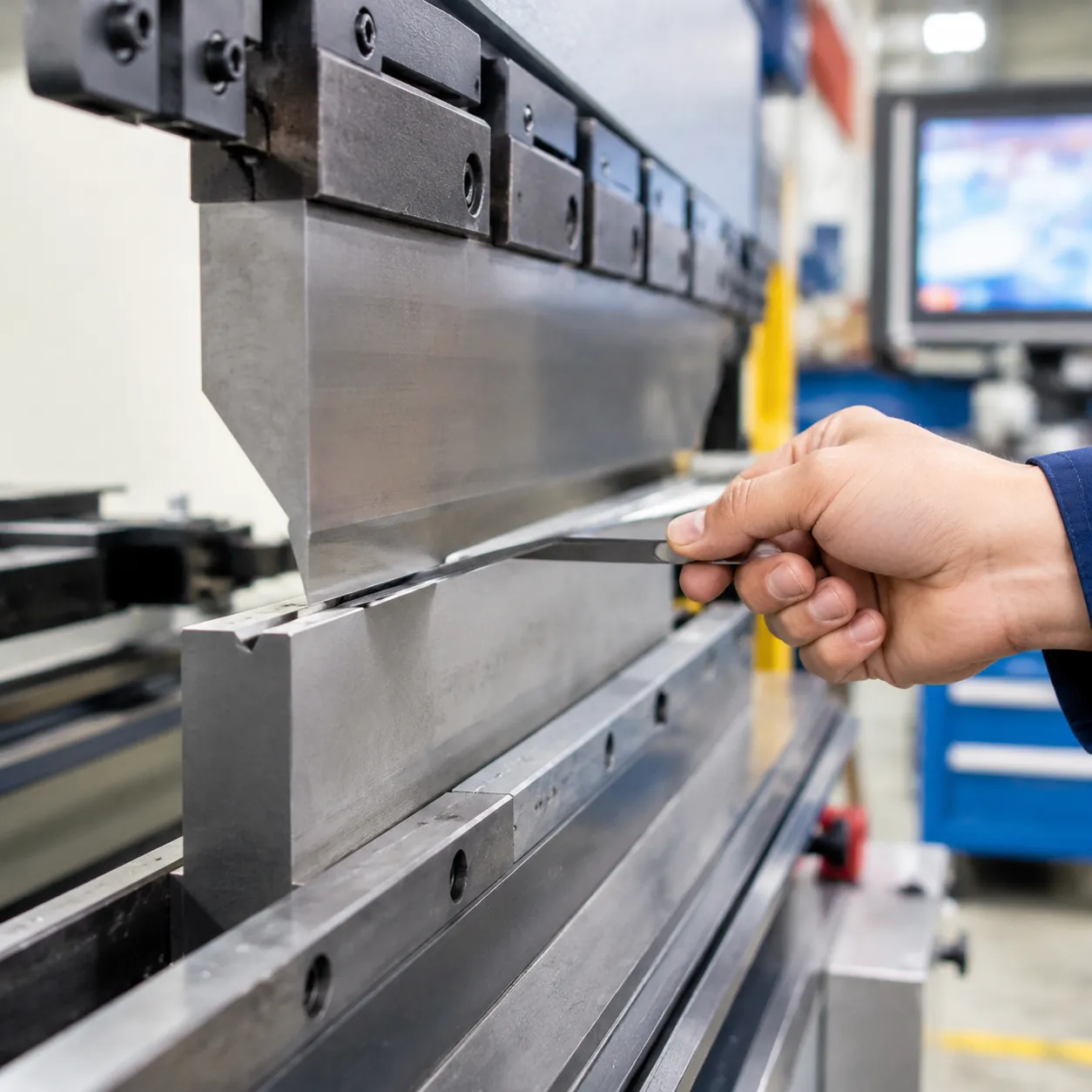
- Punch Tip Clearance: Calculating exact punch tip clearance prevents material binding and excessive friction during the stroke.
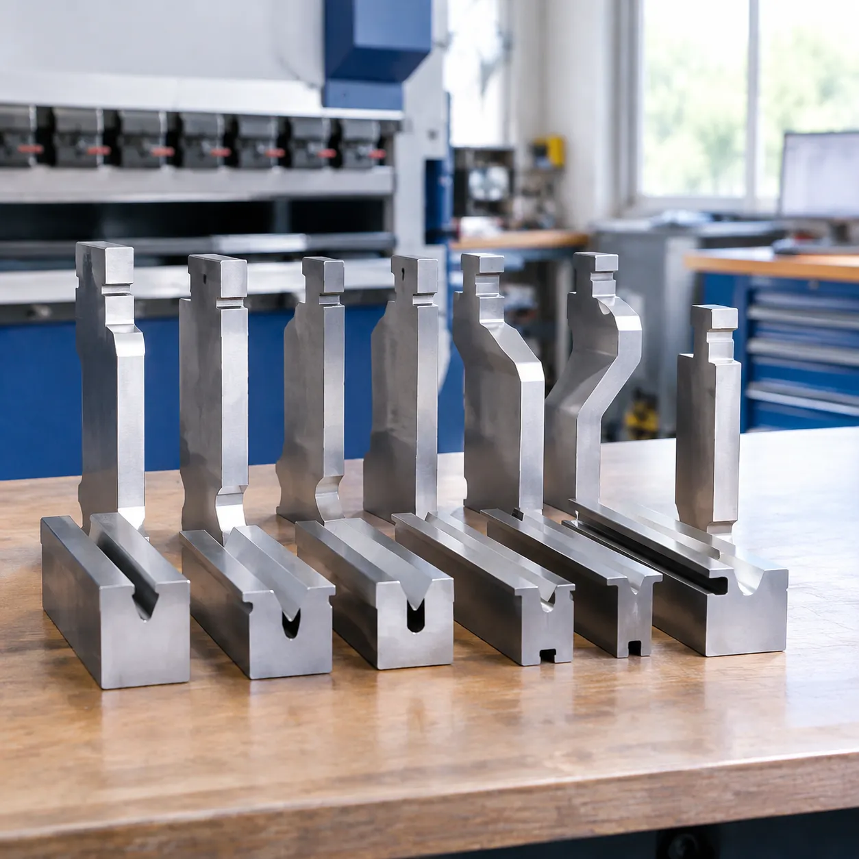
- 3D Collision Simulation: We run complete motion simulations for specialized setups—including gooseneck punch and die profiles, hemming tools, and multi-V die block configurations—verifying tool clearance against machine rams and complex workpiece flanges.
Tool Steel Selection & Raw Material Verification
Choosing the Right Alloy Steel
We evaluate three primary metal grades when manufacturing precision tooling:
- 42CrMo (4140 Chromoly): The industry standard alloy for high-performance press brake dies. It offers exceptional core toughness, uniform wear, and high fatigue resistance.
- D2 Tool Steel: Best suited for high-volume production where extreme abrasion resistance is mandatory. D2 resists surface degradation, though its higher brittleness requires careful tonnage management.
- Mild Steel (A36 / 1018): Common in temporary shop-built tooling, but strictly limited to low-tonnage applications. Unhardened mild steel deforms rapidly under repeated loading.
| Steel Grade | Core Hardness | Abrasion Resistance | Tonnage Capacity | Ideal Application |
|---|---|---|---|---|
| 42CrMo (4140) | High | Excellent | Heavy-Duty | Standard & custom OEM tooling |
| D2 Tool Steel | Very High | Maximum | High-Volume | High-wear, long-run production |
| Mild Steel (A36) | Low | Low | Light-Duty | Prototypes & short-run bending |
For a comprehensive breakdown of yield strength and alloy specs, consult our press brake tooling material guide.
Material Traceability & Quality Control
Raw material integrity must be verified before machining begins to guarantee structural safety:
- Spectrometric Chemical Analysis: We test raw billet samples using optical spectrometry to confirm exact carbon, chromium, and molybdenum percentages before hitting the mill.
- Ultrasonic Flaw Detection: Internal voids, micro-cracks, or inclusions can cause catastrophic shear under hydraulic pressure. Ultrasonic scanning ensures complete core density across the full block length.
- Core Toughness Verification: Baseline hardness testing ensures uniform grain structure, guaranteeing the raw bar reacts predictably during machining and subsequent hardening cycles.
Machining & Production Lifecycle for Press Brake Dies
3.1 Blanking & Rough Machining
When we execute the initial steps on how to make a press brake die, precision stock preparation prevents catastrophic warping later. We start by sawing stock alloy bars oversized by 3 mm to 5 mm to leave adequate stock for finish grinding. Before cutting into heavy alloys, selecting the right block grade is critical, as detailed in our press brake die material guide.
Once blanked, multi-axis CNC milling machines rough out the foundational geometry:
- V-Grooves & Profiles: Heavy milling hogging removes bulk material to rough-form single V-grooves, goosenecks, or a Multi-V die block.
- Tangs & Mounting Channels: Precision milling cuts standard American or European-style tangs, securing precise alignment in press brake clamping systems.
- Shoulder & Tip Allowances: Machining profile features while retaining 0.5 mm to 0.8 mm of grinding stock across working surfaces.
3.2 Stress Relieving & Pre-Finishing
Aggressive material removal during rough milling creates intense internal structural stresses. Hardening metal in this state causes severe twisting or cracking, making stress mitigation mandatory when learning how to make press brake die tooling that lasts.
- Thermal Stress-Relief Annealing: Rough-machined blanks are heated to 600°C–650°C (1112°F–1202°F) in a controlled furnace, held for hours, and slowly cooled to neutralize mechanical tension.
- Semi-Finish Machining: After stress relief, we run high-speed semi-finishing passes across tangs and V-grooves. This dials in critical dimensions within ±0.1 mm, ensuring uniform stock allowance across all working surfaces before deep heat treatment.
Controlled Heat Treatment & Surface Hardening
Deep Vacuum Heat Treatment
We subject the rough-machined die body to deep vacuum heat treatment to establish uniform tensile strength throughout the entire core.
- Core Stability: Hardens the alloy steel uniformly without atmospheric contamination or surface oxidation.
- Deformation Prevention: Minimizes thermal distortion, keeping long die sections straight and dimensionally stable.
- Structural Integrity: Creates a ductile, tough core capable of absorbing heavy press loads without catastrophic shear.
Localized Induction Hardening (HRC 55–60)
While the tool core requires high toughness, working contact zones demand maximum surface hardness. We apply targeted high-frequency induction hardening along the tooling shoulder radius and V-groove edges to achieve HRC 55–60.
- Extended Tool Life: Boosts operational lifespan by up to 3x compared to untreated shop tooling.
- Galling & Friction Defense: Prevents surface scoring, wear grooves, and material dragging during tight-radius sheet metal bending.
For demanding production environments, integrating localized induction hardening on custom precision press brake dies ensures consistent bend accuracy across high-volume runs.
Multi-Stage Tempering Protocols
Hardening without tempering leaves high-carbon and alloy steels prone to fracturing under load. We execute secondary tempering cycles to relieve micro-stresses while locking in the ideal working surface hardness (HRC 47–60 depending on the die geometry).
| Treatment Phase | Target Area | Hardness / Result |
|---|---|---|
| Vacuum Hardening | Entire Tool Core | Uniform tensile strength & high core toughness |
| Induction Hardening | V-Edges & Shoulder Radii | HRC 55–60 localized wear resistance |
| Secondary Tempering | Complete Die Assembly | Retains HRC 47–60 working surface; eliminates brittleness |
This controlled thermal balance ensures the finished press brake tooling resists cracking, chipping, and wear under intense forming pressures.
Precision Finish Grinding & Surface Quality
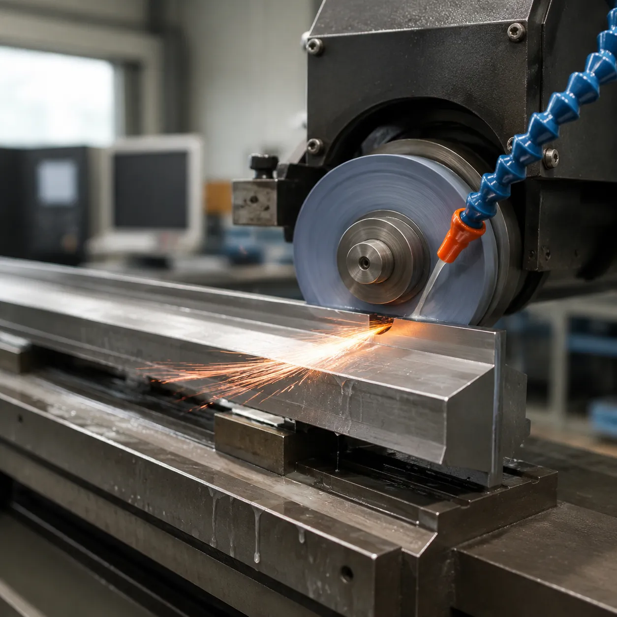
Heat treatment invariably causes minor thermal distortion. When perfecting how to make a press brake die, precision finish grinding is the non-negotiable step that restores true geometric accuracy and removes micro-imperfections.
High-Precision Profile Grinding
We rely on multi-axis CNC profile grinding to bring working profiles back into strict dimensional tolerance after heat treatment.
- Precision grinding tolerance ±0.01 mm: Keeps height profiles, tang dimensions, and V-groove center lines aligned across every section.
- Modular Repeatability: Guarantees section-to-section matching so multiple die segments sit flush on long press brake beds without step offsets.
- Center Line Alignment: Keeps the top punch and bottom die centered precisely, preventing uneven side-thrust and premature tool wear.
Surface Roughness Optimization
A rough die face increases drag and leaves unwanted tool marks on sensitive workpieces. We grind and polish all contact zones down to a surface roughness Ra < 0.8 µm.
When finishing a high-performance female press brake V-die for precise sheet metal bending, achieving low surface roughness delivers immediate operational benefits:
- Minimal Friction: Allows sheet metal to slide smoothly into the V-opening during the stroke without dragging or grabbing.
- Eliminated Sheet Scratching: Prevents galling, friction welds, and visible die marking on stainless steel, aluminum, and pre-painted stock.
- Micro-Crack Prevention: Removes surface stress risers, significantly extending die life under high-tonnage cycling.
Quality Inspection & Validation Matrix
When learning how to make press brake dies that deliver flawless bends every time, strict quality verification is non-negotiable. We subject every finished tool to exhaustive dimensional and material testing before it ever hits a hydraulic press brake setup. Our precision quality control processes ensure that every punch and die section maintains tight tolerance limits and structural integrity.
3D CMM & Optical Profile Validation
We verify geometric accuracy using high-precision 3D Coordinate Measuring Machines (CMM) and optical profile projectors. This guarantees that your tool geometry matches exact CAD models across every segment:
- Profile & Centerline Alignment: We inspect the V-die opening, shoulder radius, and tang alignment to confirm a precision grinding tolerance of ±0.01 mm.
- Section-to-Section Repeatability: Modular die sections are scanned side-by-side to ensure seamless end-to-end alignment without height variations.
- Specialized Geometry Clearance: Non-contact CMM optical inspection maps gooseneck punches and multi-V die blocks to verify tip clearance and prevent collision risks.
Hardness & Surface Finish Testing
Dimensional precision means nothing if the working surfaces wear prematurely or shear under load. We validate material hardness and surface finish through two mandatory quality gates:
| Inspection Test | Target Metric | Purpose & Operational Impact |
|---|---|---|
| Rockwell Hardness Testing | HRC 55–60 (V-edges) HRC 28–32 (Core) | Confirms targeted localized induction hardening along high-wear zones while keeping the tool core tough enough to prevent catastrophic cracking. |
| Surface Profilometry | Surface roughness Ra < 0.8 µm | Verifies ultra-smooth contact surfaces to minimize friction drag, eliminate sheet marking, and stop galling on stainless steel or pre-painted stock. |
We test hardness across both the working zones and the unhardened core to certify total structural stability before releasing the tooling to the shop floor.
In-House Tooling vs. Custom OEM Solutions
Cost, Time, and Safety Comparison
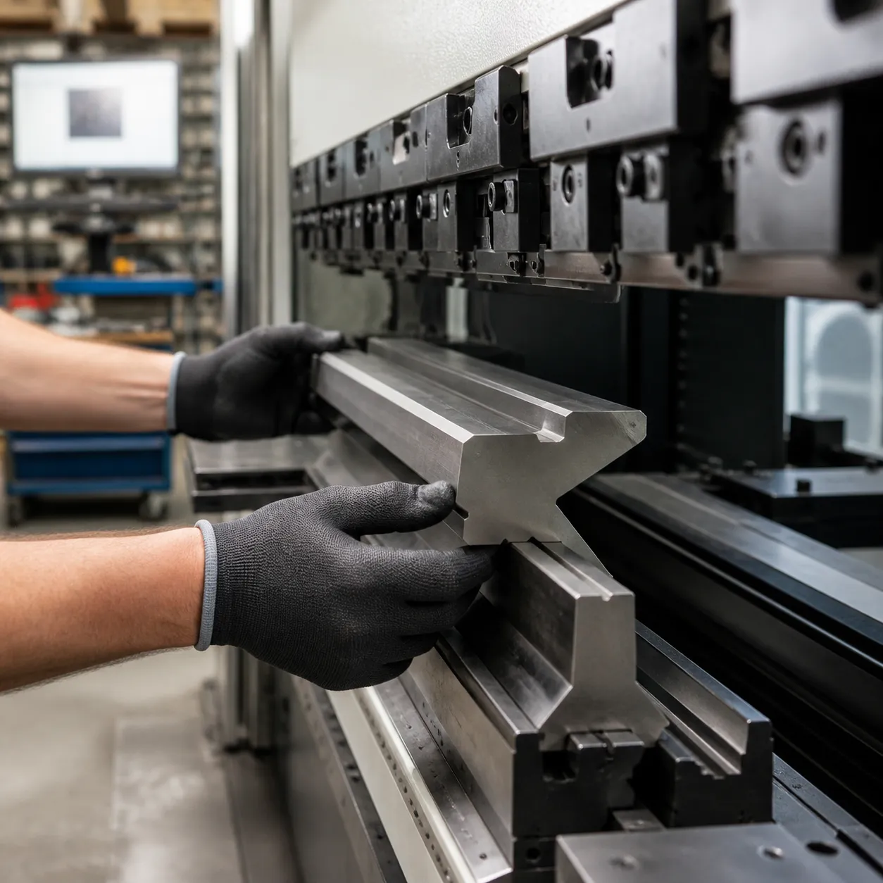
Deciding how to make a press brake die in-house versus sourcing factory-ground tooling comes down to balancing shop hours, profile accuracy, and safety under heavy press loads. Fabricating DIY hydraulic press brake tooling from unhardened stock often introduces stress points, surface marking, and catastrophic failure risks under load.
| Performance Metric | In-House Shop Tooling | CAMT Precision OEM Tooling |
|---|---|---|
| Machining Time | 20–40+ labor hours | Pre-engineered / Fast delivery |
| Tolerance Limits | ±0.05 mm to ±0.1 mm | Precision ground to ±0.01 mm |
| Tooling Longevity | Low (Rapid wear & surface scoring) | High (Induction hardened HRC 55–60) |
| Tonnage Limits | Unverified / High fracture risk | Certified safe tonnage capacity |
| Surface Quality | Standard milled (Ra > 1.6 µm) | Ultra-smooth profile (Ra < 0.8 µm) |
Custom Engineering Services by CAMT
We bridge the gap between complex sheet metal designs and shop floor production with high-precision custom press brake tooling. Instead of burning machine hours trying to figure out how to make press brake die profiles in-house, you can rely on our specialized manufacturing infrastructure.
- CAD Feasibility & Springback Evaluation: Submit your 2D/3D CAD models (STEP, DXF, DWG) for complete bend physics verification, K-factor adjustments, and springback testing.
- Fast-Track OEM/ODM Production: Specialized manufacturing for Gooseneck profiles, Hemming sets, and heavy-duty Multi-V die blocks.
- Hydraulic Adapters & Quick-Change Systems: Custom adapters designed for seamless hydraulic press brake tooling setup, reducing setup changeovers to seconds.
- Tailored Engineering: Our full-service custom tooling development delivers exact section-to-section repeatability across all modular segments.
Frequently Asked Questions
What steel alloy is best for making press brake dies?
We recommend 42CrMo alloy steel (AISI 4140) as the premier choice when evaluating how to make a press brake die for production environments. It delivers an optimal balance of core toughness, fatigue strength, and high load capacity. For ultra-high-volume runs demanding maximum abrasion resistance, D2 tool steel is the top upgrade, whereas mild steel (A36 or 1018) should only be used for low-tonnage prototyping.
How do you calculate the V-die opening for sheet metal bending?
When calculating how to make press brake die geometries for air bending mild steel, apply the standard V-die opening calculation formula: V = 8 × t (where t is sheet thickness). You can fine-tune this ratio based on sheet thickness and bend specs:
Thin sheet / tight radius: V = 6 × t
Standard sheet metal forming: V = 8 × t
Heavy plate forming: V = 10 × t to 12 × t
What hardness level (HRC) should precision press brake tooling achieve?
Working contact zones—such as the V-groove edges and shoulder radii—must achieve HRC 55–60 to prevent indentation and surface scoring. However, the non-working core should maintain a lower hardness (HRC 38–45) to retain ductility and absorb bending shocks under high tonnage.
Why is induction hardening preferred over standard heat treatment?
Localized induction hardening allows us to hard-face the main contact zones (HRC 55–60) without making the full die block brittle. Deep through-hardening makes tool steel prone to catastrophic shear under peak loading. Selective induction extends overall tool lifespan by up to 3x while keeping structural operations safe.
Should I manufacture press brake dies in-house or buy custom OEM tooling?
While building a DIY V-die press brake setup works for basic shop projects, in-house dies rarely achieve tight grinding tolerances (±0.01 mm) or low surface roughness (Ra < 0.8 µm). Sourcing precision-ground metal forming press brake dies for sale or factory-spec American style press brake tooling eliminates catastrophic tonnage failure risks and guarantees exact modular alignment across your press brake bed.
Related Sources
- https://mooremt.com/press-brake-mastering-bend-deduction-and-k-factor/
- https://www.accur
- https://www.accurtool.com/press-brake-tooling-material-selection-guide/
- https://mooremt.com/press-brake-mastering-bend-deduction-and-
- https://www.wilatooling.com/en-us/products/press-brake-tooling/american-style-tooling/