
Formula details
Product Details
Overview
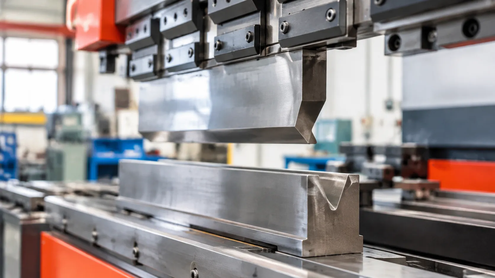
Press Brake Tooling Radius Specifications and Standard Sizing
42CrMo Material Standards and Core Hardening Depth
We build our tools to endure heavy cyclical tonnage without permanent body deformation or localized shoulder collapse.
- Base Material: Premium forged 42CrMo alloy steel (quenched and tempered) to absorb high impact shock without brittle fracturing.
- Surface Hardness: Contact zones and nose profiles undergo CNC high-frequency induction hardening reaching HRC 47–55.
- Hardening Depth: Consistent 2 mm to 4 mm case depth on working radii ensures long tool life through abrasive scale and high-tensile runs.
- Machining Tolerance: Precision ground surfaces held within ±0.01 mm to ±0.02 mm along critical contact heights for complete section interchangeability.
Standard Solid Tip Radii Options from R1.0 to R15.0 mm
Selecting the correct press brake punch radius prevents piercing the material centerline and eliminates orange-peel fractures on sensitive alloys. We supply solid-body radius punch configurations across all primary sheet thicknesses:
| Punch Tip Radius | Typical Plate Range | Primary Applications | Common Profile Angles |
|---|---|---|---|
| R1.0 mm – R2.0 mm | 0.8 mm – 2.5 mm | Precision electronic enclosures, light mild steel | 86°, 88°, 90° |
| R3.0 mm – R5.0 mm | 2.5 mm – 4.5 mm | Heavy gauge chassis, brackets, 304/316 stainless | 80°, 85°, 88° |
| R6.0 mm – R9.0 mm | 4.0 mm – 6.0 mm | Structural components, high-yield aluminum | 75°, 80°, 85° |
| R10.0 mm – R15.0 mm | 6.0 mm – 12.0 mm | Agricultural frames, heavy transport, earthmoving | 60°, 70°, 80° |
Standard Lengths and Horn-Relieved Segmentation Setups
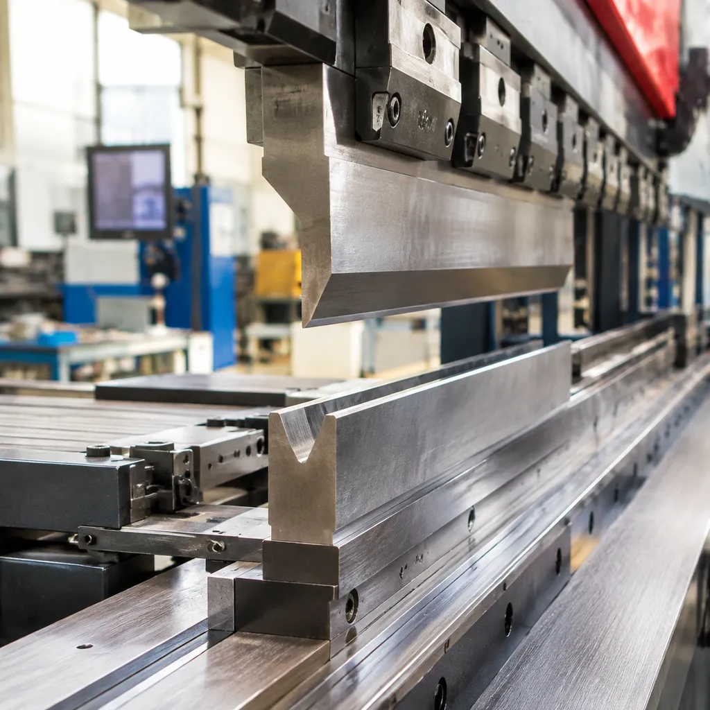
Our radius punch press brake tools are available in continuous lengths or fully modular segmented sets to clear deep side flanges, box returns, and tight return channels.
- Solid Standard Lengths: 835 mm and 500 mm full-length bars for uninterrupted continuous bends.
- Segmented Sets (835 mm Kit): Pre-split into matched segments (10, 15, 20, 40, 50, 100, 200, 300 mm) for fast assembly to any required bend length.
- Horned Relief Sections: Includes 100 mm left-hand and right-hand ear pieces (horned ends) providing direct clearance for deep-side return flanges in multi-stage enclosure bending.
Mounting Styles for Radius Punch Press Brake Applications
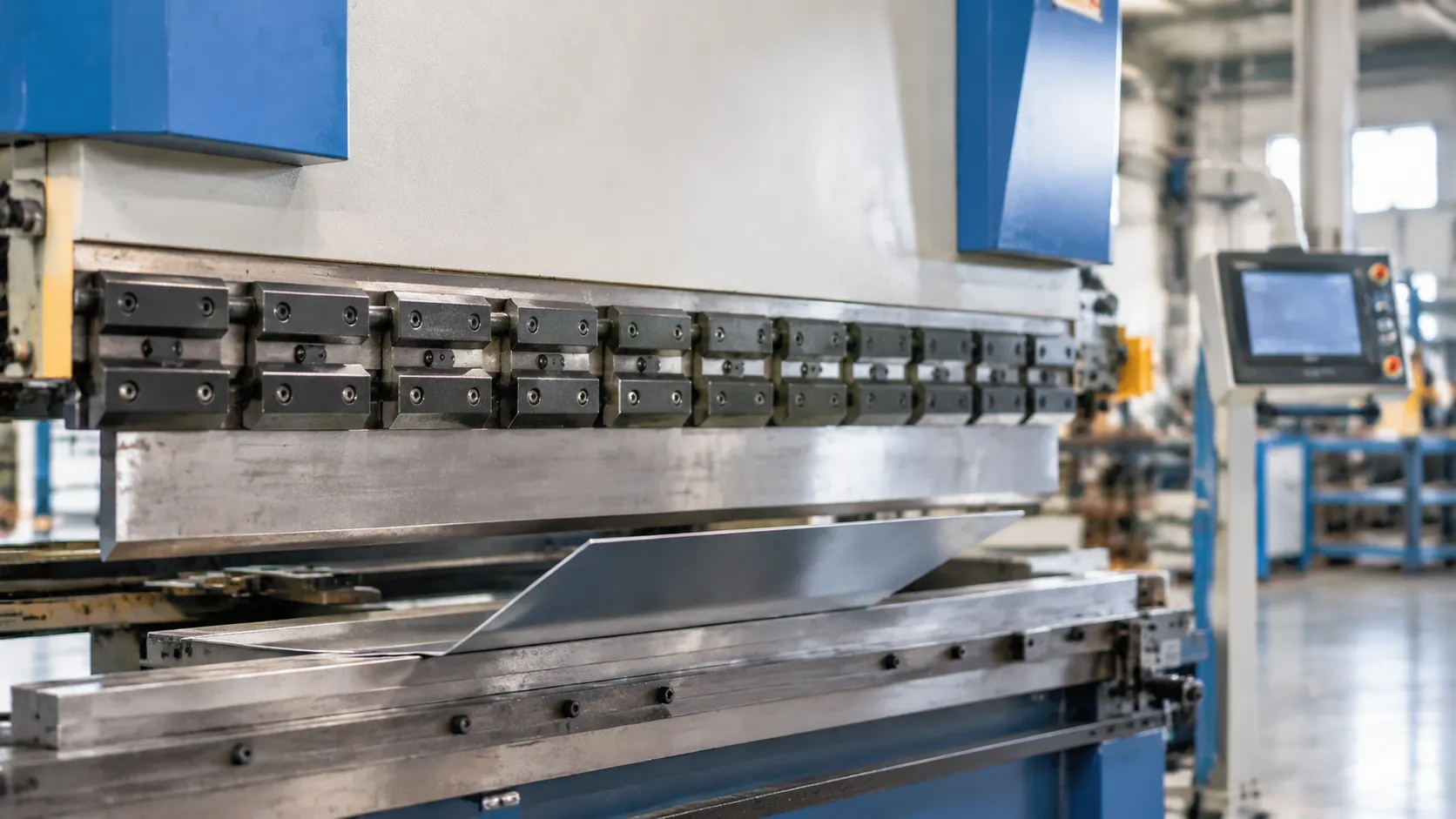
Machine downtime and uneven bend lines often trace back to mismatched tang geometry or improper tool seating under load. We manufacture our radius press brake tooling to seat directly into your existing clamping systems without requiring custom shims or adapter plates. Every profile is precision ground to maintain exact centerline alignment across individual segments.
Explore our dedicated radius punches configured for your specific machine beam setup.
| Mounting System | Tang Dimensions | Clamping Mechanism | Primary Advantage |
|---|---|---|---|
| European / Promecam | 8.4 mm width with safety groove | Mechanical clamp plate or quick-manual levers | Universal availability, fast sectional tool swaps |
| Trumpf-Wila (New Standard) | 20 mm / hydraulic tang profiles | Push-button safety pin, hydraulic or pneumatic | Automatic self-seating, extreme vertical load capacity |
| American Standard | 0.500 in (12.7 mm) straight tang | Set-screw or wedge-lock ram clamps | Rigid shoulder seating, high resistance to tool deflection |
European and Promecam Compatible Radius Punches
Our European-style radius punches feature a standard 8.4 mm tang with a precision safety shoulder.
- Compatibility: Drops directly into standard Promecam-style upper mechanical clamp assemblies, universal intermediate holders, and quick-clamp setups on machines such as Amada, Durma, and Bystronic.
- Seating: Dual-face precision ground shoulders absorb the full bending load, keeping the press brake punch radius true under repetitive cycles.
- Segmented Layouts: Fully compatible with standard split lengths to clear pre-bent side flanges and return bends.
Trumpf and Wila New Standard Self-Seating Profiles
Engineered for modern high-precision CNC bending cells, these tools use self-seating grooves and safety click mechanisms for vertical tool loading.
- Self-Alignment: As soon as clamping pressure engages, the tooling draws upward into the beam shoulder, pulling the tool centerline into dead-center alignment.
- Heavy Tonnage Capacity: Hardened contact surfaces handle severe radial loads up to 250 kN/m, preventing tang yield when forming thick high-tensile plate.
- Safety Click System: Single operators can swap out heavy, large-radius punch profiles horizontally or vertically without tools dropping out of the holder.
American Standard Straight-Tang Tooling Options
We supply traditional 0.500 in (12.7 mm) straight-tang tools engineered for North American press brakes, including Accurpress, Cincinnati, and standard mechanical rams.
- Shoulder Load Transfer: Built with wide contact shoulders to ensure tonnage is directed into the upper ram rather than putting bending moments on the tang set screws.
- Deflection Resistance: The stout tang geometry handles the lateral thrust generated during large-radius air bending and bottoming operations.
- Direct Integration: Fits standard manual clamp bars without altering beam offsets or backgauge programming coordinates.
Heavy-Duty Radius Press Brake Tooling and Modular Insert Systems
Bending large radii on heavy plate does not mean you need to buy a massive, dedicated solid punch for every single profile. Machining a massive solid punch for a single job eats into project margins and creates serious shop storage problems. To solve this, we engineer modular radius press brake tooling systems that combine a universal high-strength punch holder with detachable radius nose inserts.
Replaceable Radius Nose Inserts from R12.5 to R50 mm
Our modular systems use precision-machined, interchangeable nose profiles designed for fast swaps directly inside the machine. Instead of unseating an entire top tool, you simply swap the working tip to change your inside bend geometry:
- Available insert radii: Standard nose profiles in R12.5, R15, R20, R25, R30, R35, R40, and R50 mm.
- Core material: Machined from forged 42CrMo alloy steel, CNC ground on all seating shoulders to maintain ±0.01 mm centerline alignment.
- Surface treatment: Working surfaces are induction hardened to HRC 47–53, resisting crushing and localized galling under extreme tonnage.
- Secure mounting: Heavy-duty socket cap screws and dowel pin locator designs prevent nose shift during deep air forming or heavy bottoming runs.
Cost-Effective Punch Bodies for Large Radius Forming
Running multiple jobs with varying specifications becomes affordable when you invest in a single large radius punch holder. You keep the universal punch body locked into your ram and purchase only the specific nose radii required for upcoming jobs.
Understanding how to select the right press brake punch radius allows your operators to match exact customer drawing specifications without keeping dozens of single-purpose punches on the floor. This modular setup slashes tool changeover times, cuts tooling purchase costs by up to 60%, and drastically reduces tool storage weight in high-mix fabrication environments.
Heavy Plate Forming for Chassis, Tanks, and Structural Components
Forming heavy plate requires tooling that can disperse peak loads without fracturing the punch neck or cracking the workpiece. We build our heavy-duty radius punch press brake configurations specifically for demanding fabrication tasks:
- Truck chassis and automotive frames: Eliminates cracking along the bend line in high-strength low-alloy (HSLA) steels.
- Storage tanks and pressure vessels: Forms wide, smooth cylindrical shell sections and curved tank baffles without multi-step bump bending lines.
- Earthmoving and agricultural equipment: Handles thick structural plates (6 mm to 20 mm+) when matched with wide-opening press brake bottom dies to keep forming tonnages well inside machine limits.
- Architectural cladding: Delivers clean, sweeping curves in aluminum and stainless plate without leaving deep die gouges or material deformation marks.
How to Choose the Correct Press Brake Punch Radius
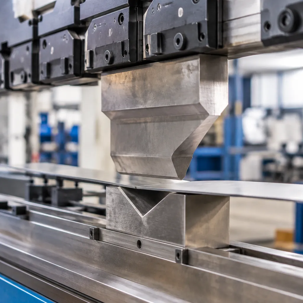
Selecting the proper press brake punch radius is critical to preventing material fracture and controlling part consistency. If your punch tip is too sharp, high-tensile materials will often crack along the bend line. Conversely, an oversized radius can lead to excessive springback and distorted bend angles.
Air Bending and Radius Dynamics
In air bending, the inside bend radius is primarily determined by the die opening and material thickness rather than the punch itself. However, using a punch with a radius smaller than the material thickness increases stress concentrations.
- Minimum Bend Radius: Always ensure the punch tip radius is at least equal to or greater than the material’s minimum bend radius to avoid surface tearing.
- Neutral Axis: For large radius forming, the neutral axis shifts, requiring adjustments to your bend allowance calculations.
- Tonnage Awareness: Larger radii distribute force over a wider area. When performing heavy-duty sheet metal radius bending, monitor your tonnage closely to prevent exceeding the machine's load capacity or the tool's rating.
Radius Selection Guidelines
| Material Type | Recommended Punch Radius | Critical Consideration |
|---|---|---|
| Mild Steel | 0.8T – 1.0T | Standard forming |
| Stainless Steel | 1.2T – 1.5T | Higher risk of cracking |
| Aluminum | 1.0T – 1.2T | Sensitive to surface marks |
Managing Tool Loads
When moving from standard tooling to specialized 90-degree press brake tooling for precise bends, ensure the punch geometry matches the required bend sequence. High-tonnage applications on thick plates can cause localized deformation if the radius is too tight. Always verify the rated pressure per meter for your specific press brake tooling radius to maintain shop safety and tool longevity.
Custom Radius Press Brake Tooling and Surface Treatments
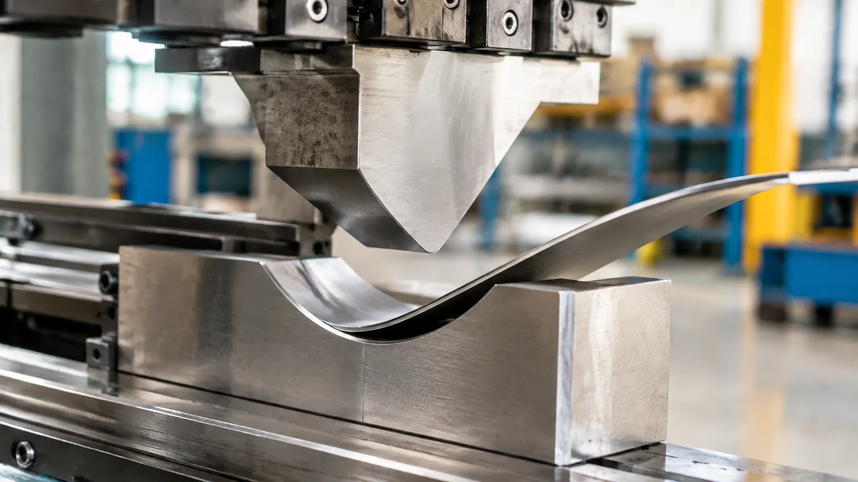
Custom Gooseneck Geometry and Special Relief Profiles
Deep box forming and tight return bends require aggressive throat depths and specialized relief windows that standard catalogs do not carry. When forming parts with pre-bent legs, an improper punch profile causes part-to-tool collision before reaching the intended bend angle.
- Extended Throat Depths: Deep-recessed gooseneck designs engineered to clear deep standing returns up to 250 mm or more.
- Window Cutouts and Relief Horns: Custom side-cut notches and ear reliefs that allow pre-formed side tabs to bypass the tool body without collision.
- Offset Radius Shanks: Specially balanced centerlines to ensure large radius noses deliver true vertical load alignment over the lower die center.
- Matched Punch-to-Die Profiles: Precision-machined sets paired according to our press brake V-die opening guide to eliminate pinch points and bottoming interference.
Nitriding and Protective Coatings to Stop Galling
High friction during large-radius air forming generates intense heat and contact pressure along the press brake punch radius, causing severe galling when running stainless steel, pre-painted stock, or high-strength aluminum. We apply targeted surface enhancements to protect both the workpiece surface and the tool nose.
- Gas Nitriding & Ferritic Nitrocarburizing: Diffuses nitrogen directly into the 42CrMo tool steel matrix, achieving surface hardness up to HRC 60 with a depth of 0.3 to 0.5 mm without distorting core ductility.
- Anti-Friction Surface Polishing: Precision micro-polishing down to Ra 0.2 µm along the working radius profile, drastically reducing sliding friction and sheet marking.
- Specialized PVD Thin-Film Coatings: Hard coatings like TiCN or CrN applied to the radius punch press brake tip to prevent material transfer, pick-up, and localized micro-welding when bending abrasive or galvannealed materials.
Direct CAD-to-Tool Engineering and Bend Clearance Simulation
We manufacture directly from your native 3D CAD part models to verify that the specified press brake tooling radius works flawlessly before any steel is machined.
- Clearance Collision Checks: We run digital simulation checks against your machine’s stroke limits, backgauge travel, and clamping envelope to guarantee zero interference during the entire stroke.
- Springback and Neutral Axis Mapping: We account for material yield strength, rolling direction, and projected springback angles to profile the correct punch tip radius and included relief angle into the solid tool body.
- CNC Profile Grinding: Every custom tool is ground on continuous multi-axis CNC profile grinders within a strict tolerance of ±0.01 mm, ensuring complete interchangeability across multi-section setups.
Press Brake Punch Radius FAQs
What is the difference between punch tip radius and inside bend radius in air bending?
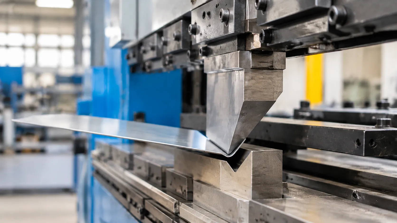
In air bending, the press brake punch radius and the resulting inside bend radius (IR) of your finished part are rarely identical:
- Natural Inside Radius: In standard air forming, the inside radius is produced by the width of the V-die opening, typically running 15% to 17% of the V-opening for mild steel and roughly 20% for stainless steel.
- Punch Tip Radius Influence: As long as your press brake punch tip radius is smaller than this natural inside radius, the tool merely acts as a pushing point. The sheet creates its own radius in the air pocket.
- Tool-Dominant Bending: When your punch radius is larger than the natural radius of the V-die, the material wraps tightly against the tool profile. In this case, your tool nose directly dictates the final inside radius.
| Forming Scenario | Tool Condition | Resulting Inside Bend Radius (IR) |
|---|---|---|
| Standard Air Bend | Punch Radius < Natural Air IR | Determined entirely by V-die width |
| Large Radius Air Bend | Punch Radius > Natural Air IR | Matches the punch tip profile |
| Bottom Bending / Coining | Punch penetrates fully to bottom | Exact mechanical imprint of the punch nose |
How do I select the right punch radius to stop sheet metal cracking?
Sheet metal cracking happens when you exceed the material's elongation limit along the outer bend fiber. To stop fractures across high-tensile steels, heavy plates, or hard-temper alloys, we match the press brake tooling radius directly to the material’s minimum bend radius:
- Mild Steel (A36, CR4): Use a punch radius equal to at least 1.0x sheet thickness.
- Stainless Steel (304, 316): Work with a radius of 1.5x to 2.0x sheet thickness to handle strain hardening.
- Structural Aluminum (6061-T6): Requires 2.5x to 4.0x sheet thickness to avoid severe shear tearing along grain lines.
- Grain Direction Check: Always bend transverse (across) the rolling grain when working tight profiles. If bending parallel to the grain is unavoidable, jump up one full punch radius size.
Can radius inserts fit into my existing European punch holders?
Yes. Our modular radius press brake tooling uses standardized heavy-duty punch bodies machined with standard European / Promecam tangs (20 mm with safety grooves).
- Direct Compatibility: The punch holders slide directly into your existing manual clamps or hydraulic clamping systems without modifying the machine beam.
- Interchangeable Inserts: The holder body stays mounted on your press brake, while replaceable radius noses ranging from R12.5 mm up to R50 mm lock securely into the base via front-facing Allen bolts.
- System Flexibility: We also manufacture these modular holders with Trumpf-Wila and American standard tanged profiles so you can run the same insert tooling across mixed-brand bending lines.
What tonnage limits apply to segmented radius tooling under offset loads?
Segmented sections under concentrated or off-center loads face higher localized stress than full-length solid tools. We engineer our segmented radius punches from high-yield 42CrMo alloy steel, but working loads must be monitored closely:
- Standard Continuous Load: Solid lengths support up to 100 tons/meter (t/m) depending on the nose radius and tang geometry.
- Short Segment Restrictions: Short pieces (10 mm to 50 mm segments) should not be subjected to point loads exceeding 50% of nominal rating without backing support from adjacent tools.
- Side-Thrust & Offset Allowance: Off-center forming induces bending moments on the punch tang. For asymmetrical or single-side horn bending, de-rate your machine's applied bending tonnage by 30% to 40% to avoid tang distortion or shoulder galling.
Why are horn-cut punch ends necessary for box and return flanges?
Horn-cut punch ends (left and right ear pieces) feature machined relief pockets on the outermost top edges of the tool segment.
- Clearance for Pre-Bent Sides: When bending four-sided boxes, trays, or deep deep-side panels, already-formed return flanges swing upward into the tool path.
- Preventing Flange Collision: The horn cutouts create a 45° to 90° clearance gap that lets deep vertical flanges bypass the clamping zone without colliding with the punch holder.
- Pairing Profiles: For deep box work with steep inner returns, fabricators typically combine horned radius tips with specialized gooseneck punches or standard press brake punches to maintain rigid tool support without sacrificing part profile clearance.