Formula details
Product Details
Overview
Adjustable Press Brake Die Overview
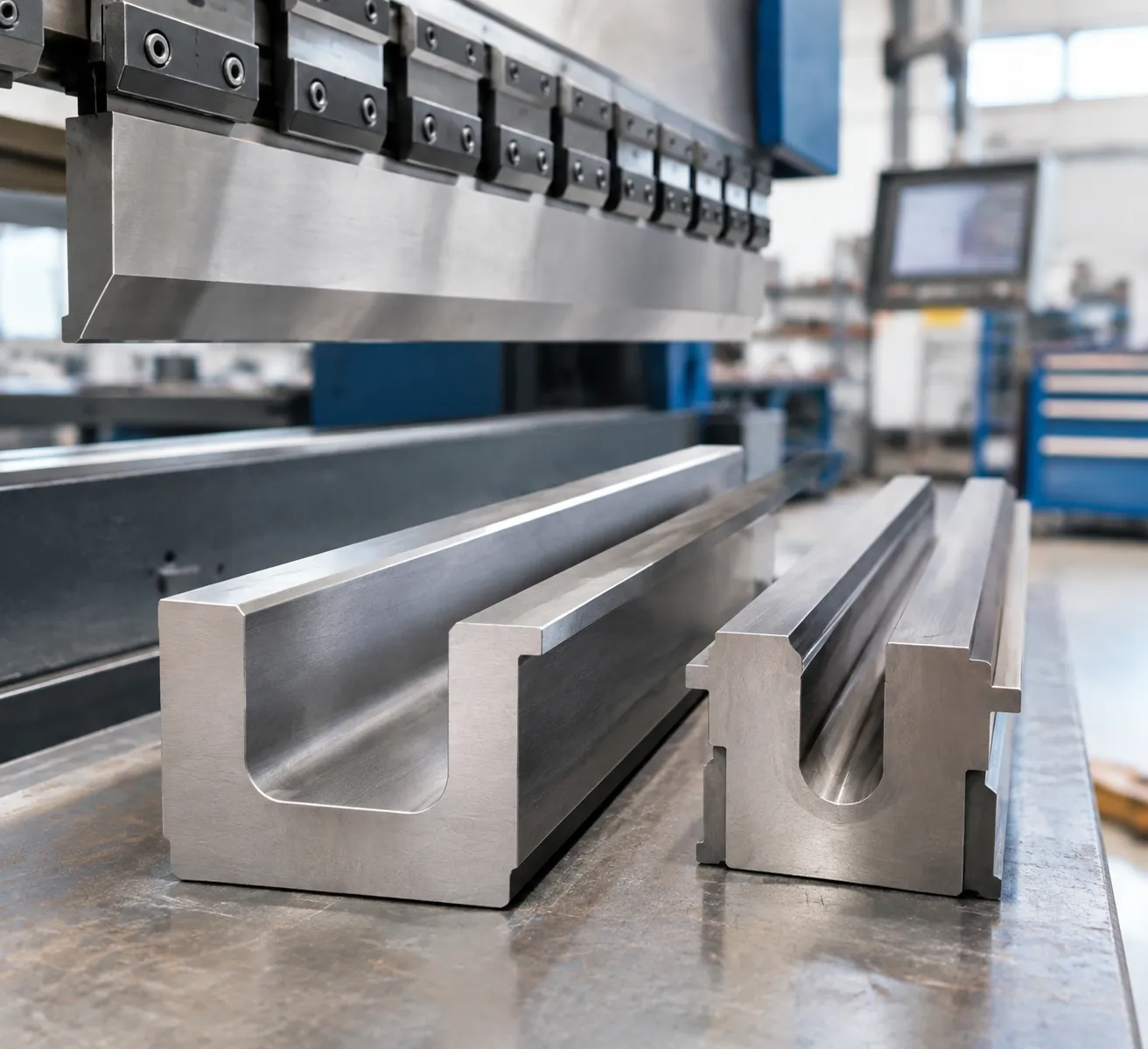
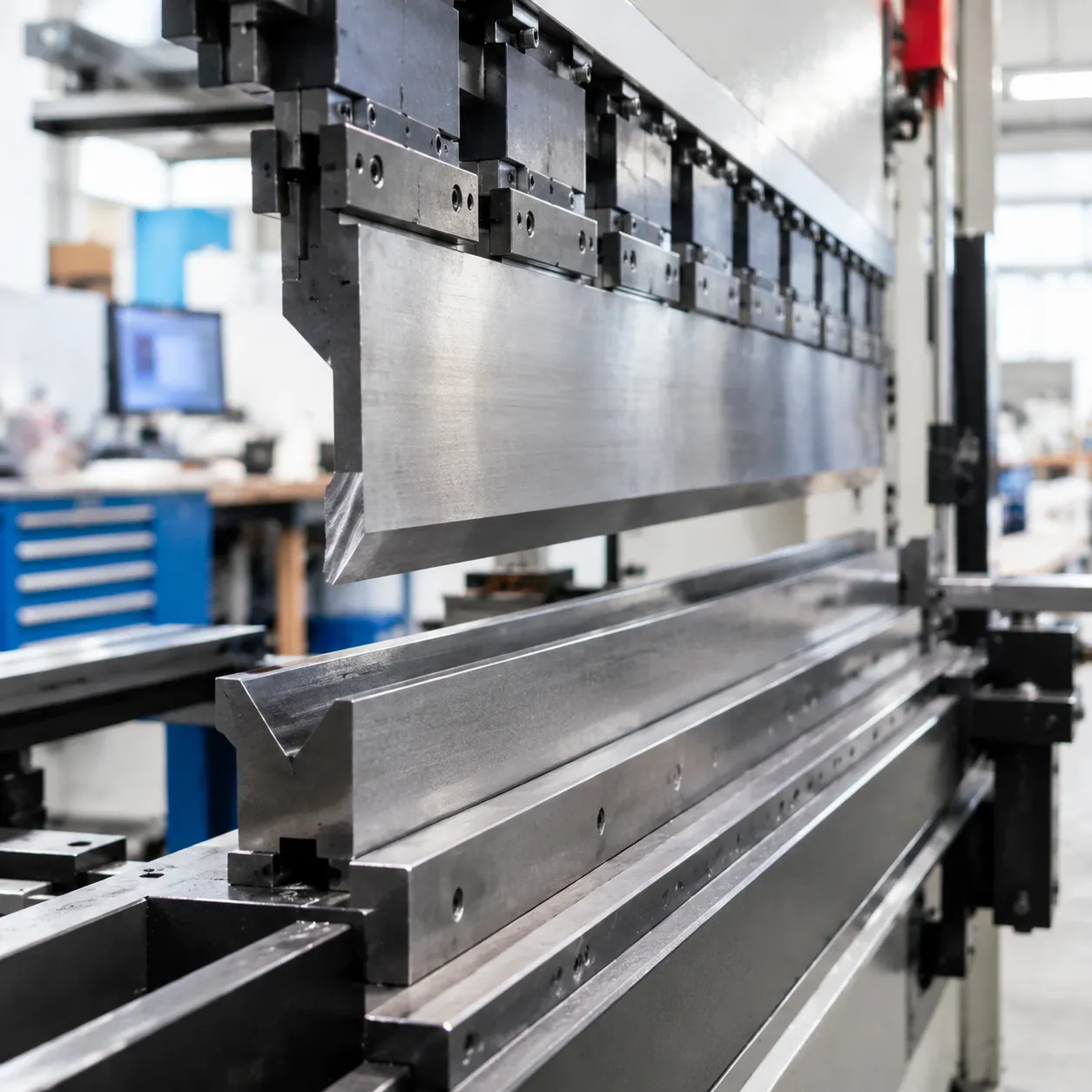
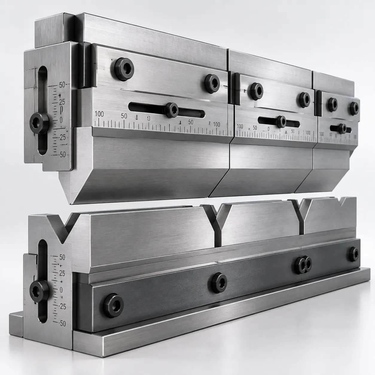
An adjustable press brake die is an advanced bottom tooling system engineered to streamline sheet metal bending operations. Instead of requiring machine operators to physically swap heavy, fixed-opening bottom blocks for different material thicknesses, our variable-opening lower tooling allows seamless width adjustments directly on the press brake bed.
Continuous / Incremental V-Width Adjustment on a Single Lower Die
→ Eliminates heavy tool swaps → Minimizes downtime → Saves space
Core Function of Variable-Opening Lower Tooling
The primary function of an adjustable V-die is providing a dynamic bending width without removing the base from the press brake bed:
- Dynamic Width Variation: Precision spacer bars, mechanical shims, or synchronized drive screws adjust the V-opening width across a defined working range.
- Universal Bending Centerline: Maintains a true theoretical bending center across all opening adjustments, eliminating the need to recalibrate backgauges.
- Continuous Sheet Support: Hardened entry rollers or high-radiused contact edges minimize surface friction and prevent work marking during high-tonnage forming.
Key Fabrication Benefits and Changeover Reduction
Frequent tool changeovers are the single largest bottleneck in modern metal forming. Our adjustable bottom die designs eliminate repetitive manual handling and crane usage.
| Operational Challenge | Standard Fixed V-Dies | Our Adjustable Press Brake Die |
|---|---|---|
| Setup & Changeover Time | 15–45 minutes per profile change | Under 1 to 3 minutes via quick-adjust system |
| Crane & Rigging Overhead | Required constantly for heavy dies | Virtually eliminated once the die is seated |
| Tooling Storage Footprint | Large racks for dozens of single dies | Single compact footprint on the machine bed |
| Operator Safety Risk | High risk of strain/crush injuries | Low physical handling, controlled adjustment |
| Machine Utilization Rate | Low during high-mix production | Maximizes CNC arc-on bending time |
Target Sheet Metal Industries and Workpiece Applications
Our adjustable sheet metal bending tooling is purpose-built for high-mix, low-volume (HMLV) job shops and heavy-duty structural manufacturing facilities.
- Heavy Machinery & Earthmoving Equipment: Forming high-strength steel plates for chassis, crane booms, and excavator buckets.
- Contract Job Shops & Metal Service Centers: Seamlessly processing sheets ranging from 2 mm thin gauges up to 25 mm heavy plates in consecutive runs.
- Commercial Vehicle & Trailer Fabrication: Bending long structural crossmembers, side walls, and chassis rails.
- Energy, Power & Structural Enclosures: Fabricating utility enclosures, transformer cabinets, bridge plates, and structural channel profiles.
Key Features of the Adjustable Press Brake Die
Variable V-Opening Design for Multi-Thickness Forming
Instead of hauling heavy, separate bottom blocks off the rack for every gauge shift, our variable V-die lets operators widen or narrow the V-groove smoothly across a broad spectrum of sheet metal thicknesses.
Continuous or stepped adjustments: Shift from tight openings for 1 mm sheet up to large spans for 16 mm+ heavy plate in seconds.
Optimized bend profiles: Achieve exact inner radii without swapping tools. For standard geometry references, consult our press brake die size chart and dimensions guide to align sheet gauge with ideal die width.
Rotational hardened entry rollers: Replace standard static die shoulders with hardened rollers to drastically cut surface scratching and lower required bending tonnage.
Heavy-Duty Hardened Tool Steel Construction
We machine each adjustable bottom die from high-strength alloy tool steel (typically premium 42CrMo or Cr12MoV) specifically heat-treated to resist heavy shock loads and localized galling.
| Component / Parameter | Material & Treatment Standard | Shop-Floor Benefit |
|---|---|---|
| Die Base Body | 42CrMo / High-Tensile Alloy | Absorbs extreme line loads without bed deflection |
| V-Opening Working Edges | Induction Hardened (56–60 HRC) | Prevents shoulder grooving and edge deformation |
| Entry Bearings / Rollers | Through-Hardened Roller Steel | Minimizes sheet drag and eliminates tool galling |
| Guide Rails | Precision Ground & Nitrided | Ensures zero lateral play over years of heavy use |
Precision Positioning Mechanisms and Scale Repeatability
Consistent air bending requires zero drift on the V-width centerline. Our variable opening systems include:
Direct-read metric rulers & Vernier scales: Rapid visual verification during manual adjustments.
Mechanical lead screw / shim locking: Prevents die spread under high tonnage.
Digital readout or CNC servo integration: Connects directly into modern press brake controllers for automated V-width setup.
Mounting Configurations and Machine Holder Compatibility
We configure the lower mounting tangs to fit virtually any press brake machine bed without custom machining:
Standard European / Promecam Style: Direct fit on 12.7 mm and 13 mm slotted bases.
Wila / Trumpf Style Clamping: Fast hydraulic or mechanical clamping with safety pins.
Universal Bolted Bases: Engineered flat-bottom mountings with locating pins for heavy-duty CNC press brakes.
Technical Specifications and Parameters
Standard Adjustable Die Specifications
The table below outlines the core baseline parameters for our standard mechanical and CNC-controlled variable tooling units:
| Specification Parameter | Standard Range / Values | Heavy-Duty Platform |
|---|---|---|
| Material Base | 42CrMo / 4140 Chrome-Moly | Hardened Tool Steel (Cr12MoV / D2) |
| Working Surface Hardness | 52 – 56 HRC (Induction hardened) | 58 – 62 HRC (Through-hardened options) |
| Adjustable V-Opening Range | 25 mm to 160 mm (Manual/Mechanical) | 60 mm to 400 mm+ (Hydraulic / CNC drive) |
| Shoulder Radius (Roller Type) | R4 mm – R12 mm (Replaceable hardened inserts) | R15 mm – R25 mm (Heavy plate handling) |
| Standard Sectional Lengths | 500 mm, 1000 mm, modular segments | Full-bed lengths up to 6000 mm single-piece |
| Adjustment Drive Mechanism | Manual lead screw or worm gear drive | Fully integrated hydraulic or CNC servo drive |
| Die Height (Working Height) | 120 mm to 220 mm | 250 mm to 450 mm custom blocks |
| Tang / Base Mounting | 13 mm × 20 mm European / 1/2" Amada-style | Direct-to-bed bolted flange / custom tangs |
Critical Parameters Required for Sizing and Ordering
Before our engineers can build or quote your adjustable bottom die assembly, we confirm three critical boundary parameters to guarantee seamless fitment and bed clearance:
- Machine Bed & Ram Details: Exact press brake model, overall working length, maximum tonnage rating, open height (daylight), stroke length, and bottom rail mounting style.
- Target Sheet Metal Specs: Maximum and minimum material thickness, yield strengths (e.g., Q235 mild steel, SS304, Hardox), and the tightest target bend angles required.
- Flange and Punch Clearances: Minimum inside flange requirements and top punch profiles to eliminate tool interference during high-depth acute air bending.
Load Ratings, Line Load Limits, and Tonnage Capacities
Overloading tooling leads to shoulder cracking, bed deflection, and permanent misalignment. Every adjustable lower die features rated line-load thresholds calculated per linear meter based on steel tensile limits and roller support geometry.
- Maximum Centerline Tonnage: Standard-duty models typically support between 1,000 kN/m and 2,500 kN/m (approx. 100 to 250 tons per meter). Heavy-plate variants achieve up to 4,000 kN/m line load capacity.
- V-Opening Load Variation: Rated tonnage changes depending on where the adjustable jaws sit. A wide V-opening spreads bending forces differently across the base compared to a narrow aperture. Always cross-reference the European press brake die rating guide for tonnage safety to prevent exceeding side-wall stress limits.
- Operating Ton-Force Checks: To avoid catastrophic tool fatigue, calculate your actual punch force using a standard press brake V-die chart and tonnage guide before executing small-radius bends in thick plate. Safe line loading prevents hydraulic drive drift and extends jaw life across high-volume production runs.
Working Principle and Design Mechanics
How Variable Bottom Tooling Operates Under the Punch
An adjustable press brake die replaces multiple single-opening blocks with a dynamic, multi-stage platform. Our design centers on two symmetrical sliding jaws mounted to a rigid base saddle. When adjusting the V-width, the jaws shift inward or outward simultaneously along high-precision guide tracks, maintaining exact centerline alignment with the upper punch.
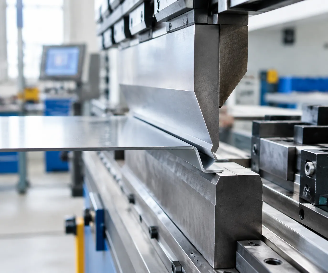
During the bending stroke, the sheet metal rests across hardened, precision-ground shoulder radii or integrated rolling bars. As the punch descends, the adjustable V-gap supports the plate at the exact calculated contact points, allowing consistent air bending across varied thicknesses without altering the bed's physical setup.
Adjustable V-Die vs. Fixed V-Die Performance Comparison
Replacing conventional fixed tooling with an adjustable bottom die eliminates the continuous cycle of crane rigging, die alignment, and storage retrieval.
| Operational Factor | Standard Fixed V-Die | Adjustable Press Brake Die |
|---|---|---|
| Setup & Changeover Time | 15 to 45 minutes per profile switch | Under 2 minutes via mechanical or CNC adjustment |
| Die Storage Footprint | Requires racks for dozens of heavy blocks | Single compact die base handles multiple V-sizes |
| Crane & Forklift Dependency | Heavy dies require rigging for every swap | Stays seated on the press brake bed continuously |
| Thickness Flexibility | Limited to one specific gauge per V-groove | Continuous or multi-step V-ranges for plates 1 mm to 25 mm+ |
| Centerline Consistency | Realignment needed after every physical change | Centerline remains locked across all V-opening settings |
While conventional press brake dies excel in dedicated single-gauge production, variable bottom tooling significantly lowers overall operating costs in high-mix environments.
Manual vs. Mechanical vs. Hydraulic Adjustment Systems
We configure variable opening dies with three distinct drive mechanisms depending on your production mix and automation level:
- Manual Spacer and Shim Systems: Operators set the V-opening using precision-ground drop-in spacer bars or manual side lead screws with calibrated Vernier scales. This configuration provides extreme structural rigidity and lower upfront cost, making it ideal for job shops running small-to-medium batches.
- Mechanical Motorized Drive: Driven by an integrated electric motor and synchronized lead screws, this system adjusts the opening via a push-button digital readout or basic machine interface. It cuts physical operator effort and speeds up adjustments between light-gauge sheet runs.
- Hydraulic Adjustable Bottom Die: Fully integrated with the machine CNC unit. Synchronized hydraulic cylinders automatically adjust the V-opening according to the programmed bend sequence. This setup delivers the fastest changeovers and is the industry standard for high-tonnage heavy plate fabrication where manual adjustments are inefficient.
Fabrication Advantages of an Adjustable Press Brake Die
Standard bending operations lose significant productive hours to tooling changeovers and alignment resets. Integrating an adjustable press brake die into your press brake tooling system eliminates recurring bottlenecks, streamlines floor operations, and delivers measurable cost savings across diverse production runs.
Slashing Tooling Setup and Changeover Downtime
Traditional tooling requires operators to hoist heavy, fixed-opening dies off the bed and re-align centerlines for every material gauge shift. An adjustable V-die transforms this workflow:
Instant V-Opening Adjustments: Switch from bending 2 mm sheet to 10 mm plate in seconds via CNC-driven motors or manual mechanical shims.
Continuous Centerline Retention: The die center stays aligned to the machine ram during adjustment, cutting out the need for tedious manual re-centering.
Higher Machine Uptime: Drastically reduces machine idle time between production batches, keeping your press brake running at peak capacity.
Reducing Bottom Die Inventory and Storage Footprints
A single variable opening V-die replaces an entire rack of single-V and multi-V blocks:
Lower Capital Investment: Buying one versatile die system costs significantly less than purchasing 6 to 12 individual precision-ground lower dies.
Reclaimed Floor Space: Clears out heavy storage racks and minimizes crane transport risks across the shop floor.
Minimized Tool Handling Wear: Fewer die changes mean fewer accidental drops, edge chips, and handling damages.
| Tooling Setup Comparison | Conventional Fixed V-Dies | Adjustable Press Brake Die |
|---|---|---|
| Changeover Time | 15–40 minutes per setup | Under 2 minutes (CNC/Manual) |
| Storage Requirement | 6–12 dedicated die slots | Single mounted die station |
| Crane / Hoist Use | Frequent for heavy dies | Rare (stays on machine bed) |
| Centerline Alignment | Required every tool swap | Permanent bed alignment |
Enhancing High-Mix, Low-Volume Job-Shop Flexibility
For custom job shops handling custom prototypes and short production batches, rigid tooling slows throughput. Deploying adjustable sheet metal fabrication tooling lets operators take on diverse orders without stopping to source or order specialty die openings. You can run one-off brackets, switch to thick chassis panels, and return to thin enclosures seamlessly on the same machine station.
Improving Workflow Consistency Across Varied Sheet Materials
Material batches often vary in tensile strength, surface condition, and actual thickness:
Micro-Adjustments for Springback: Fine-tune the V-opening by precise increments to counter material springback without changing top punches.
Consistent Flange Quality: Maintain uniform bend radii across mild steel, stainless steel, and aluminum by matching the opening exactly to the material yield properties.
Smooth Surface Finish: Hardened, low-friction roller options on the die shoulders eliminate galling and drag marks on sensitive polished or coated sheets.
V-Opening Selection and Application Guide
Selecting the right opening width on an adjustable press brake die determines bend precision, tonnage load, and finished part quality. Our engineering team designed this guide to help operators quickly dial in exact dimensions across multiple plate grades without guesswork.
Calculating Optimal V-Opening and Inside Bend Radius
The opening width (V) dictates the natural inside bend radius (Rᵢ) during air bending. We recommend establishing the opening based on material thickness (T):
- Standard Sheet (0.5 mm to 3.0 mm): Set opening width to 6 × T to 8 × T.
- Medium Plate (4.0 mm to 8.0 mm): Set opening width to 8 × T to 10 × T.
- Heavy Plate (10.0 mm and above): Set opening width to 10 × T to 12 × T to prevent cracking and reduce machine load.
- Resulting Inside Radius: For air bending mild steel, Rᵢ ≈ V / 6.
Evaluating Tonnage, Minimum Flange Width, and Punch Profile
Before cycling the ram, verify the physical limits of your setup:
- Bending Tonnage: Narrowing the V-opening increases required bending force. Doubling the V-opening cuts the required tonnage roughly in half.
- Minimum Flange Width: The sheet must rest flat across both shoulders before forming begins. Calculate the safe minimum flange as b_{min} approx 0.7 × V.
- Punch Profile Compatibility: Ensure the punch nose radius and tip angle clear the die shoulders without bottoming out or colliding during acute angle strokes.
V-Opening Sizing Formula:
Mild Steel: V = 8 × Material Thickness (T)
Minimum Flange (b): b = 0.7 × V
Inside Radius: Rᵢ ≈ V / 6
Material Compatibility Across Steel, Stainless, and Aluminum
Different metal alloys behave differently during forming:
- Mild Steel: The standard benchmark for variable opening calculations. Use 8× T for clean 90 ° bends with minimal springback.
- Stainless Steel: Delivers higher tensile strength and greater work-hardening. Open the die to 10× T or 12× T and prepare for increased springback during demanding stainless steel processing applications.
- Aluminum Alloys: Softer grades crack easily along the grain line if bent over tight radii. Follow our press brake die selection for aluminum guide by expanding the variable V-opening to 8× T to 10× T to preserve outer surface integrity.
When to Deploy Adjustable Tooling vs. Dedicated Fixed Dies
| Factor | Adjustable Press Brake Die | Dedicated Fixed Single-V Die |
|---|---|---|
| Production Style | High-mix, low-volume job shops | Dedicated high-volume mass production |
| Material Range | Multi-thickness plates (3 mm to 30 mm+) | Single gauge thickness |
| Setup Time | Under 2 minutes via mechanical or CNC drive | 15–30 minutes manual heavy tool swaps |
| Shop Floor Space | Single compact footprint on machine bed | Extensive storage racks for multiple die blocks |
| Special Geometries | Best for straight air bends and variable radii | Best for tight Z-bends, hem bends, and special profiles |
Machine Compatibility and Installation Steps
Pre-Purchase Press Brake Compatibility Checklist
Before ordering, our engineers evaluate your press brake to ensure seamless mounting and full stroke clearance:
- Bed Mount and Tang Profile: Confirm your bed style—whether American standard tang, European/Promecam, Trumpf-Wila, or direct bolted. When planning a press brake die replacement for American or European styles, verify that the tang height and width match your bed slot exactly.
- Open Height and Stroke Length: Variable V-dies generally have a taller baseline profile than small single-V blocks. Verify your press brake has sufficient daylight (open height) to clear both the tall lower die and your punch during full retraction.
- Bed Tonnage Limits: Ensure your machine's bed line-load capacity (tons per meter or foot) supports concentrated bending forces when using narrower V-openings on heavy plate.
- Controller Integration: For motorized or hydraulic adjustable bottom dies, verify if your CNC controller can send opening commands directly or if a standalone digital readout (DRO) unit is preferred.
| Compatibility Parameter | Verification Requirement |
|---|---|
| Mounting Tang | Standard 0.5" × 0.625", 13 mm × 20 mm, or T-nut |
| Daylight (Open Height) | Die Height + Punch Height + Safety Clearance |
| Max Machine Bed Load | Rated tons/meter > Calculated bending tonnage |
| Drive Clearance | Unobstructed access for manual shims or motor |
Step-by-Step Die Mounting and Centerline Alignment Procedure
Precise centering ensures balanced wear on both die shoulders and maintains consistent angle accuracy across your parts:
- Bed Preparation: Thoroughly clean the press brake bed surface, removing all metal chips, scale, and oil film.
- Position the Lower Die: Lower the adjustable press brake die onto the bed rail, centering it along the longitudinal axis of the machine.
- Snug Mounting Clamps: Hand-tighten the lower die clamps or tang set screws just enough to hold the tooling upright while allowing micro-lateral movement.
- Punch-Assisted Center Alignment: Install your top punch, select a wide V-opening setting on the bottom die, and jog the upper ram down in manual/setup mode at low speed until the punch tip seats into the V-groove.
- Torque Clamping Hardware: With light ram pressure holding the die centered against the punch, tighten the mounting bolts working from the center outward to recommended factory torque specifications.
Initial Low-Tonnage Test Bend Verification and Troubleshooting
Always perform an initial dry run and a low-tonnage test bend before starting full production:
- Dry Cycle Check: Run the punch through a full stroke without material to verify that the punch profile clears the variable die shoulders at minimum and maximum opening settings.
- Test Bend with Scrap Material: Set the adjustable V-opening to the target width, lock the mechanical adjustment blocks or hydraulic drive, and perform an air bend on a test strip of your intended material.
- Troubleshooting Alignment and Angle Variations:
- Angle variation from center to ends: Check your machine crowning settings or inspect the bed for localized debris under the die base.
- Flange scuffing or asymmetrical legs: Re-verify that the punch tip is dead-centered within the adjustable V-groove.
- Stiff or binding adjustment mechanisms: Disassemble slide spacers or clean side guide tracks to blow out accumulated laser oxide and scale dust.
Adjustable Press Brake Die Safety, Maintenance, and Longevity
Protecting your investment in an adjustable press brake die requires strict tonnage management and routine maintenance. Because variable-opening tooling relies on moving mechanical segments, keeping components clean, aligned, and properly lubricated prevents catastrophic failure and preserves bend accuracy over years of high-tonnage production.
Operating Within Rated Machine and Die Tonnage Limits
Exceeding line-load limits is the fastest way to ruin precision tooling and damage machine beds. We engineer each adjustable V-die with specific load capacities that change based on your selected opening:
- Calculate line loads upfront: Always calculate required bending force per foot or meter before cycling the ram. Narrower openings concentrate force over smaller surface areas.
- Never exceed shoulder ratings: Running heavy plate over small openings can generate point loads that crack hardened shoulder radii.
- Distribute loads evenly: For staged or off-center bending, confirm the machine bed and the adjustable bottom die base are balanced to eliminate uneven side-thrust.
- Sync machine stops: Ensure CNC depth limits and hydraulic relief valves prevent accidental bottoming out when air bending.
Daily Cleaning, Debris Clearance, and Lubrication
Mill scale, metal shavings, and slag build up quickly on lower tooling. In an adjustable system, debris trapped between sliding jaws leads to uneven V-openings, premature galling, and binding.
Following dedicated press brake die maintenance tips for longer tool life keeps your shop floor running without unexpected downtime:
- Blow down and wipe: Clear scale from the adjustment tracks, guide rails, and V-shoulders at the start of every shift using compressed air and industrial degreaser.
- Lubricate moving parts: Apply clean synthetic grease or extreme-pressure (EP) way lube to lead screws, manual adjustment wedges, and guide blocks daily.
- Keep bottom cavities clear: Regularly vacuum out the base housing beneath the adjustable segments to stop accumulated slag from preventing full jaw retraction.
Spotting Early Signs of Wear, Chipping, and Deformation
Catastrophic tool failure rarely happens without warning. Inspecting your adjustable press brake die during pre-shift checks highlights minor issues before they ruin parts:
| Checkpoint | What to Look For | Corrective Action |
|---|---|---|
| Shoulder Radii | Galling, scuff marks, or local spalling | Polish smooth with fine abrasive stone; verify lubrication |
| Adjustment Jaws | Uneven gaps or looseness along the bed | Retighten locking pins and check lead-screw play |
| Working Edges | Micro-cracking or visible material chipping | Stop operation immediately; redress or replace segment |
| Tool Centerline | Angular deflection across long bends | Re-verify machine bed shimming and die base clamping |
Customization Options and Manufacturing Standards
Every shop faces unique bending challenges, which is why we build each adjustable press brake die to exact job requirements. Whether bending high-tensile armor plate or precision enclosures, we tailor our variable-opening tooling to your machine specifications and target tonnage.
| Specification | Standard Build | Custom Options Available |
|---|---|---|
| V-Opening Range | 20 mm–400 mm | Up to 600+ mm continuously variable |
| Total Length | 500 mm to 4100 mm solid | Custom segmented lengths or sectional |
| Overall Working Height | 120 mm–220 mm | Engineered heights to match daylight |
| Base Mount Style | Standard 13 mm × 20 mm tang | Wila, Trumpf, Promecam, or direct bolting |
| Steel Grade | 42CrMo (4140 equivalent) | Cr12MoV, D2, or Hardox wear inserts |
| Surface Hardness | 48–52 HRC (working shoulders) | Nitrided / hard-chromed up to 58–62 HRC |
Tailored Tool Steel and Surface Hardening
We select high-grade alloy tool steels formulated to handle high point-load stresses without structural fatigue. For heavy-duty plate work, we apply deep-induction or laser hardening on critical contact radii, ensuring the working surfaces resist galling and premature wear when processing abrasive materials.
Precision CNC Machining and Quality Control
Our manufacturing facility follows rigid ISO-certified processes to guarantee exact parallelism across full-length beds:
Deep CNC Milling & Grinding: Working surfaces and sliding channels are finish-ground within a ±0.01 mm tolerance to prevent taper along long bends.
Laser Centerline Inspection: Every adjustable section undergoes CMM dimensional validation to ensure true alignment with your top punch.
Compatibility Matching: Beyond our variable systems, our engineering team manufactures matched press brake bottom dies to ensure seamless integration with your existing machine holders and beds.
Export-Grade Protective Packaging
To prevent damage and rust during long-distance transit, our tooling undergoes a multi-stage preservation process:
Application of heavy-duty, industrial rust-preventative oil on all machined surfaces.
Vacuum-sealed, moisture-barrier vapor corrosion inhibitor (VCI) wrapping.
Reinforced, custom-fitted solid wooden export crates secured with steel strapping to prevent movement during international transport.
Direct Ordering and Quoting Process for Adjustable Press Brake Dies
Getting the right adjustable press brake die configured for your shop floor requires zero guesswork. We streamline the entire procurement cycle from initial data intake to final shop delivery, ensuring your variable opening die drops directly onto your machine bed with zero fitment issues.
| Procurement Stage | Key Customer Inputs / Actions | Engineering Deliverables | Turnaround Time |
|---|---|---|---|
| 1. Data Intake & Request | Machine model, tonnage, sheet materials, thickness range | Initial feasibility check & commercial quotation | 24 Hours |
| 2. Engineering Review | Drawing sign-off, profile confirmation, clamp verification | 2D/3D approval drawings, tonnage load analysis | 1–2 Business Days |
| 3. Build & Dispatch | Final order confirmation | Precision CNC machining, load testing, tracking details | Standard Production Lead |
Submitting Machine Specs, Sheet Grades, and Target Profiles
To engineer your adjustable bottom die to exact working parameters, we collect practical operational data upfront. This prevents over-tonnage hazards and guarantees seamless integration with your existing machine setup:
- Machine Make and Clamping System: Bed length, total rated tonnage, and specific holder mounts, including direct tang setups compatible with Trumpf tooling or hydraulic Wila tooling style receivers.
- Material Grades and Tensile Strengths: Details on the metals you process daily—such as mild steel, high-strength structural plate, or stainless steel.
- Plate Thickness and Required Openings: Minimum and maximum thickness variations to pinpoint the right adjustable V-opening range (such as V=25mm to 200mm or custom heavy-duty ranges).
- Bending Profile Clearances: Target bend angles, critical return flanges, and punch tip radii to verify physical tooling clearances.
Engineering Compatibility Review and Technical Drawing Sign-Off
Once we evaluate your application data, our tooling engineers run a detailed load calculation to verify point loads and line tonnage limits. We generate detailed 2D production blueprints and 3D step files showing the exact die profile, drive mechanisms (manual lead screw, external gear drive, or integrated CNC hydraulics), and center line locations.
Fabrication starts only after your tooling manager signs off on the final engineering drawings, locking in exact dimensions, mounting shanks, and mechanical travel limits.
Precision Fabrication, Functional Load Testing, and Delivery Tracking
Every adjustable sheet metal bending tooling assembly undergoes strict quality-controlled manufacturing:
- Precision CNC Machining: Working surfaces, saddle ways, and guides are machined to tight dimensional tolerances.
- Deep Hardening: High-wear contact radii undergo deep induction hardening to resist continuous high-tonnage deformation.
- Functional Movement and Load Verification: We cycle the variable-opening mechanism across its full adjustment stroke and perform structural alignment checks before crating.
- Secure Dispatch and Real-Time Tracking: Completed tooling is preserved with anti-corrosion oil, sealed in barrier wrap, packed into reinforced export-grade wooden cases, and dispatched with end-to-end tracking to your facility.
Frequently Asked Questions (FAQs)
What is an adjustable press brake die and how does it operate?
An adjustable press brake die is a variable-opening lower tooling system engineered to change its V-width without requiring the operator to physically swap out tooling blocks. Using mechanical shims, leadscrew drives, or integrated CNC hydraulic cylinders, the opposing die shoulders move symmetrically inward or outward. This continuous or stepped adjustment allows our tooling to accommodate multiple sheet thicknesses and bend radii on a single setup.
How does an adjustable V-die differ from a standard multi-V die?
While a traditional multi-V block features fixed, pre-machined slots requiring manual rotation and crane flipping, an adjustable bottom die stays locked in place on the bed.
| Feature | Adjustable Press Brake Die | Standard Multi-V Die |
|---|---|---|
| Adjustment Method | Leadscrew, shims, or CNC hydraulics | Manual lifting and 90°/180° rotation |
| Setup Time | Under 1–2 minutes | 15–30 minutes (requires crane/rigging) |
| Opening Range | Continuous or fine-step incremental | Fixed 3–4 specific slot sizes |
| Safety Profile | Eliminates heavy block turnover risks | High pinch and drop risks during flipping |
Can one adjustable die replace all my lower press brake tooling?
For medium-to-heavy plate fabrication and high-mix production, a single adjustable vee die can replace dozens of dedicated single-V blocks across your standard air bending operations. However, specialized profiles—such as acute hemming, deep box bending with high return flanges, or specialized radius forming—still benefit from dedicated metal forming press brake dies for sale tailored to distinct geometries.
Is manual adjustment or hydraulic adjustment better for my shop?
- Manual adjustment (shim or screw-driven): Best for job shops with moderate run sizes where opening adjustments happen a few times per shift. It offers an economical entry point with zero hydraulic maintenance.
- Hydraulic CNC adjustment: Essential for high-mix, low-volume runs and automated cell bending. The CNC controller commands opening widths instantly between bend steps, eliminating operator intervention.
How do I ensure the adjustable die fits my specific CNC press brake?
We customize our bottom tangs and mounting bases to match all primary machine standards, including European/Promecam, American standard, Amada, Bystronic, and Trumpf styles. When pairing with existing press brake die sets for sale, we verify your machine’s open height, stroke length, bed table width, and total tonnage capacity to guarantee safe mechanical clearance.
What sheet metal thicknesses and materials can be bent safely?
Our variable opening die systems handle materials ranging from 1 mm (0.040 in) sheet up to 30 mm (1.18 in) heavy armor plate. We construct each die from deep-hardened 42CrMo or equivalent high-tensile tool steel, making them fully rated for:
Mild steel (CR4 / HR4 / A36)
High-strength structural steel (Hardox, Strenx)
Stainless steel (304, 316)
Heavy aluminum alloys (5052, 6061)
What routine maintenance keeps an adjustable die running smoothly?
- Daily cleaning: Blow out mill scale, metal debris, and laser slag from the guide slots and sliding tracks using compressed air.
- Lubrication: Apply high-pressure sliding grease or dry-film anti-wear lubricant to all guide rails and adjustment screws at weekly intervals.
- Shoulder inspection: Check hardened shoulder rollers and contact points for pitting or scoring to maintain consistent bend angles.
What exact specifications do I need to supply for a quotation?
To help our engineers size your adjustable tooling accurately, provide:
Press brake specifications: Make, model, total tonnage, bed length, and base mounting slot style.
Target material parameters: Minimum and maximum sheet thicknesses, material yield strengths, and target bend radii.
Adjustment preference: Manual screw, spacer/shim, or fully automated hydraulic CNC operation.