Core Selection Rules: The V-Opening to Material Thickness Ratio
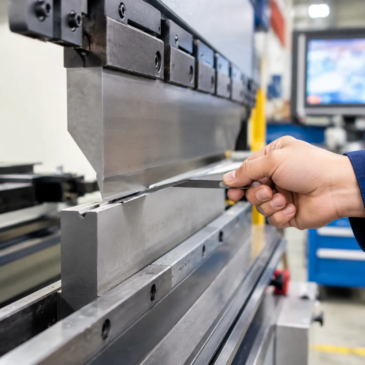
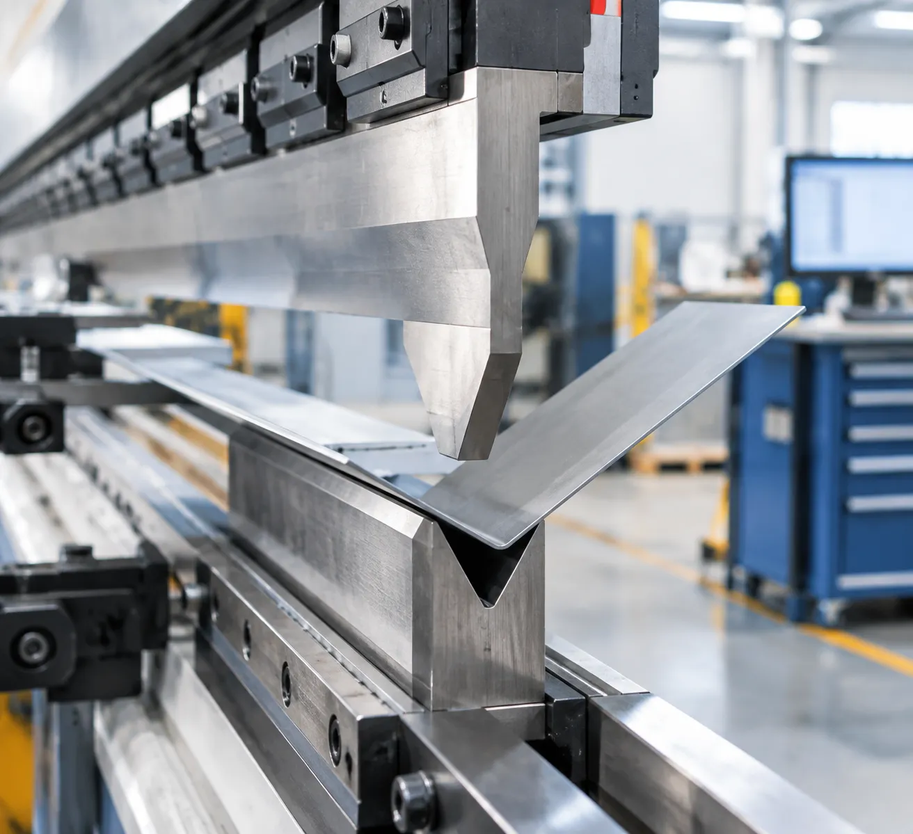
In precision sheet metal fabrication, determining the correct die geometry dictates your forming accuracy, tonnage load, and finished part quality. Air bending with press brake bottom die opening parameters relies directly on matching the material thickness (T) to the inner width of the bottom V-die (V). Selecting this opening correctly prevents machine overload, eliminates surface fracture, and maintains tight angular tolerances across every production run.
V-Die Opening (V) = Multiplier × Material Thickness (T)
| Material Category | Yield Strength / Characteristic | Recommended V-Ratio | Typical V-Opening Formula |
|---|---|---|---|
| Mild / Low Carbon Steel | Standard cold-rolled (e.g., A36, SPCC) | 6xT to 8xT | V = 8 × T |
| Stainless Steel | Work-hardening, high yield (304, 316) | 8xT to 10xT | V = 10 × T |
| Soft Aluminum | Ductile (5052-H32, 1100) | 6xT | V = 6 × T |
| Hard Aluminum | High-strength, cracking risk (6061-T6) | 8xT to 10xT | V = 8 × T |
| High-Strength / Wear Plate | Extreme tensile / Hardox / Weldox | 10xT to 12xT | V = 10 × T to 12 × T |
The Standard 8xT Rule for General Sheet Metal Fabrication (T <= 6mm)
For standard precision bending where material thickness is 6mm or less, the 8x material thickness rule (V = 8 × T) serves as the universal baseline:
- Balanced Forming Load: Keeps bending tonnage well within standard hydraulic press brake limits.
- Controlled Inside Radius: Generates a natural inside bend radius roughly equal to the material thickness (R_i \approx 1.0T to 1.25T).
- Tooling Longevity: Minimizes concentrated stress on hardened 42CrMo die shoulders, preserving tool edge integrity.
Mild Steel and Low Carbon Steel: 6xT to 8xT Sizing Guidelines
Mild steel exhibits excellent ductility, giving operators flexibility between tight radii and low-tonnage setups:
- 8xT Configuration (Standard): Delivers optimal angular repeatability and low tool wear.
- 6xT Configuration (Tight Geometries): Applied when drawings specify a smaller inside radius or shorter minimum flange lengths.
- Tonnage Impact: Using a 6xT opening increases the required forming tonnage by roughly 30% compared to an 8xT opening.
Stainless Steel Adjustments: 8xT to 10xT for High Yield Strength
Stainless steel requires wider bottom die openings to counter rapid strain hardening and elevated yield strengths:
- Opening Range: Standardize on 8xT to 10xT (typically V = 10 × T for 300-series grades).
- Springback Control: Higher tensile resistance generates severe springback; wider dies allow deeper punch penetration with acute tooling (85° or 88° dies) to hit nominal angles.
- Surface Integrity: Wider die widths distribute shoulder contact pressure, eliminating premature galling and tooling pickup.
Aluminum Alloys: Selecting 6xT to 8xT for Soft vs. Hard Grades
Aluminum selection depends on alloy temper and grain direction:
- Soft Grades (5052-H32, 3003-H14): Run reliably at 6xT to 8xT without edge peeling or cracking.
- Structural/Hard Grades (6061-T6, 7075): Require a minimum of 8xT to 10xT combined with generous punch tip radii. Tight V-openings force excessive outer-fiber elongation, causing severe cracking along the bend line.
High-Strength and Hardox Plate: 10xT to 12xT Opening Parameters
Air bending high-tensile steels (Strenx, Domex, Hardox) demands specialized bottom die selection:
- V-Opening Dimension: Set to 10xT to 12xT (scaling up to 14xT for extreme heavy-duty plate).
- Load Management: Mitigates the massive tonnages required to deform high-yield materials.
- Fracture Prevention: Expands the bend radius, keeping outer-fiber strain below the critical threshold to prevent catastrophic material failure.
Bottom Die Opening for 2mm Sheet Metal: Sizing Guide
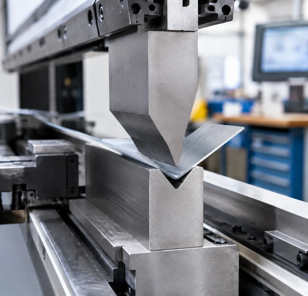
Selecting the proper air bending bottom die opening for 2 thick materials (such as 2mm mild steel, stainless, or aluminum) directly controls your tonnage, inside bend radius, and minimum allowable flange. When setting up air bending with press brake bottom die opening standards in our shop, we balance machine load with part geometry to guarantee repeatability.
Baseline Standard: V = 16mm (8xT) for 2mm Mild Steel
For standard 2mm carbon and mild steel, the industry standard baseline is an 8x material thickness rule (V = 8 × T).
- Selected Die Opening: V = 16 mm
- Why it works: It offers the ideal trade-off between manageable bending force, minimal tool wear, and stable angle accuracy.
- Tooling choice: A standard 85° or 88° female press brake V-die delivers accurate air bend angle control while accounting for standard material springback.
Alternative V-Widths: V = 12mm (6xT) vs. V = 20mm (10xT)
Depending on your part drawings, you may need to step away from the standard 16mm opening:
- Alternative V = 12mm (6xT) — Tighter Radius & Shorter Flanges:
Use a 12mm V-opening when the drawing calls for a tight inside radius or a narrow flange that would otherwise fall into a 16mm opening. Keep in mind that bending force increases by approximately 30% to 35%, requiring you to monitor machine capacity. - Alternative V = 20mm (10xT) — High Strength & Surface Protection:
For 2mm stainless steel (such as 304 or 316) or high-yield alloys, stepping up to a 20mm opening reduces peak tonnage and prevents surface scoring, cracking, and severe machine strain. Reviewing our press brake die clearance guide ensures your punch and die pairing prevents side-wall interference during deep bends.
- Alternative V = 12mm (6xT) — Tighter Radius & Shorter Flanges:
Inside Bend Radius (Rᵢ) and Minimum Flange Rules for 2mm Sheet
2mm Air Bending Setup Comparison Chart
The table below outlines the core parameters when air bending 2mm mild steel (yield strength \approx 420 MPa) across different bottom die openings:
| Bottom Die Opening (V) | Ratio (V/T) | Natural Inside Radius (Rᵢ) | Minimum Flange Length (bₘᵢₙ) | Estimated Tonnage (per meter) | Primary Application |
|---|---|---|---|---|---|
| V = 12 mm | 6 × T | ≈ 1.9 mm | ≈ 9.0 mm | ≈ 22–24 tons/m | Short flanges, tight inside corner specs |
| V = 16 mm | 8 × T | ≈ 2.6 mm | ≈ 12.0 mm | ≈ 16–18 tons/m | Standard baseline for 2 mm mild steel |
| V = 20 mm | 10 × T | ≈ 3.2 mm | ≈ 15.0 mm | ≈ 13–15 tons/m | Stainless steel, cosmetic parts, reduced tonnage |
Scaling Up: Die Opening Guidelines for Thick Plate Bending (T >= 6mm to Heavy Plate)
When moving beyond light-gauge sheet to heavy plate fabrication, the standard rules shift. Bending thick materials requires a larger bottom die opening to manage extreme forces, prevent machine overload, and avoid fracturing the outer bend radius.
Why the 8xT Rule Fails on Thick Materials: Cracking and Machine Overload
Applying the standard 8xT ratio on materials 6mm and thicker creates serious shop-floor risks:
Severe Tonnage Spikes: Forcing heavy plate into an undersized V-opening drives tonnage requirements through the roof, risking hydraulic bypass, frame deflection, or tool failure.
Tensile Fractures on the Outer Radius: Thick plate cannot stretch as easily as thin sheet metal. Forcing a tight bend radius causes the outer grain structure to tear and crack.
Tool Damage: Extreme contact pressure on narrow die shoulders leads to rapid pitting, shoulder deformation, and punch tip chipping.
Applying the 10xT to 12xT Rule for Heavy Section Air Bending
For heavy plate air bending, we use wider ratios to balance structural integrity with manageable tonnage.
| Material Thickness (T) | Material Type | Recommended V-Opening (V) | Inside Bend Radius (R_i \approx 0.16 × V) |
|---|---|---|---|
| 6mm – 8mm | Mild Steel | 10 × T (60mm – 80mm) | ~9.6mm – 12.8mm |
| 10mm – 12mm | Mild Steel | 10 × T to 12 × T (100mm – 144mm) | ~16.0mm – 23.0mm |
| 16mm – 20mm+ | Heavy Structural Plate | 12 × T (190mm – 240mm+) | ~30.0mm – 38.0mm |
| 6mm – 12mm | Hardox / High-Tensile Steel | 12 × T to 14 × T | Varies by yield strength |
For shops processing varied heavy plate runs without constant tool swaps, an adjustable press brake die for precision metal bending provides the flexibility needed to set exact V-widths on demand.
Die Shoulder Geometry: Large-Radius Shoulders to Prevent Galling and Friction Spikes
Standard sharp die shoulders cannot handle the friction generated during heavy air bending. When heavy plate drags over narrow shoulder edges, extreme drag resistance spikes required tonnage and scores the workpiece.
- Large-Radius Entry Shoulders: Heavy-duty dies feature expanded shoulder radii (R5 to R15+) to allow smooth material flow into the V-cavity.
- Reduced Friction & Galling: Generous shoulder transitions prevent deep gouges and mill-scale buildup.
- Surface Hardening: We manufacture these bottom dies from heat-treated 42CrMo alloy steel with induction-hardened shoulders (HRC 47–53) to resist wear under continuous high-load cycles.
Tonnage Capacity Checks for Heavy Duty Plate Air Bending
Before executing heavy plate air bending with a press brake bottom die opening, always verify that your machine rating and tooling load limits exceed the calculated bending force per meter:
- Calculate Required Tonnage: Ensure the tonnage calculated using your selected V-opening width stays within 70–80% of your press brake's continuous rated capacity.
- Tooling Centerline Load Limits: Heavy plate applications demand robust tooling geometry, such as a specialized 250 ton press brake die set for heavy metal bending, to prevent catastrophic tooling fracture under concentrated loads.
- Flange Clearance: Account for the wider die footprint when checking backgauge clearance and part return paths.
Technical Trade-Offs Dictated by the Press Brake V-Opening
Every parameter in precision bending is tied directly to the width of your die. When configuring your air bending with press brake bottom die opening, changing the V-width forces a direct compromise between required machine load, inside radius geometry, minimum flange limits, and springback control.
V-Opening vs. Machine Tonnage: Mathematical Inverse Relationship
Bending tonnage shares an inverse relationship with the bottom die opening width. As a rule of thumb, doubling the die width cuts the required bending tonnage roughly in half.
The practical press brake V die opening formula for tonnage estimation in air bending is:
- Bending Force (Tons/Meter) = (1.42 x Tensile Strength x Thickness²) / V-Opening
Narrowing the die opening increases friction and resistance at the die shoulders, spiking hydraulic pressure. Widening the V-width relieves machine strain, which is critical when sizing the air bending bottom die opening for 2 thick materials—whether running 2mm gauge sheet or thick 20mm plate on machines with limited tonnage capacity.
| Die Opening Ratio | Machine Tonnage Required | Inside Radius (Ri) | Minimum Flange Required |
|---|---|---|---|
| 6xT (Narrow) | Highest (+30% to +40%) | Smallest (~0.15 x V) | Shortest (~0.7 x V) |
| 8xT (Standard) | Nominal Baseline (100%) | Standard (~0.16 x V) | Standard (~0.75 x V) |
| 10xT to 12xT (Wide) | Lowest (-20% to -35%) | Largest (~0.18 x V) | Longest (~0.85 x V) |
V-Opening vs. Inside Bend Radius (Ri): Calculating the Natural Float Radius
During air bending, the punch nose does not force the sheet to conform to its profile unless bottoming occurs. Instead, the material naturally floats across the shoulders of the die:
- Inside Bend Radius (Ri) ≈ 15% to 17% of the V-Opening (or roughly Ri = V / 6 for standard mild steel).
- For 2mm Mild Steel in a 16mm V-Die: Ri = 16mm / 6 ≈ 2.67mm.
- For 2mm Stainless Steel in a 20mm V-Die: Ri = 20mm / 5.5 ≈ 3.63mm.
Using a die opening that is too wide generates an excessively large inside bend radius, shifting your bend deductions and throwing off overall blank development.
V-Opening vs. Minimum Flange Length: Formulas to Avoid Sheet Drop-In
The sheet must bridge across both die shoulder radii throughout the stroke. If the flange dimension is too short, the workpiece slips down into the die cavity before reaching the target angle, resulting in ruined parts and potential tool damage.
We calculate the safe minimum flange length V opening boundary using:
- Minimum Flange Length (b_min) ≈ 0.7 x V to 0.8 x V (depending on shoulder radius).
For short-flange jobs, operators often switch to narrower V-openings to keep the workpiece supported. Utilizing flexible setups like a 10-way multi-V die or a dedicated 3-inch American-style press brake die with 3 V-openings allows operators to rapidly match changing flange requirements on a single setup.
V-Opening vs. Angular Consistency and Springback Compensation
Die width directly influences elastic recovery and angular consistency:
- Wider V-Openings: Create a larger natural inside radius, spreading plastic deformation over a wider zone. This results in higher sheet metal springback compensation values (up to 3° to 5° in high-strength materials) and requires deeper punch penetration to achieve the final bend angle.
- Narrower V-Openings: Concentrate the bending moment at the centerline, creating a sharper bend with minimal springback and tighter angular tolerance. However, they significantly increase tool shoulder wear and surface marking.
Troubleshooting: Risks and Defects of Incorrect Die Sizing
Undersized Die Opening (V < 6xT): Premature Tool Wear, Punch Chipping, and Tonnage Overload
Dropping below the 6xT ratio spikes forming resistance exponentially:
- Tonnage Surges: Bending force climbs rapidly when forcing material into a narrow groove. This risks exceeding your press brake’s tonnage limits per meter and overloads the hydraulic system. Check our press brake V-die chart and tonnage guide to verify load thresholds before sizing down.
- Shoulder Galling and Wear: Extreme contact pressure accelerates shoulder wear and causes deep groove scoring on the die shoulders.
- Punch Tip Fracture: Concentrated counter-forces increase the risk of chipping or snapping hardened punch tips under load.
Undersized Die Opening (V < 6xT): Surface Gouging, Orange Peeling, and Outer Radius Cracking
Narrow V-grooves damage both the cosmetic and structural integrity of the workpiece:
- Severe Die Shoulder Marks: Deep drag lines and gouges form on both sides of the bend as the sheet draws over tight shoulder radii.
- Orange Peeling: High tensile strain on the outer bend zone stretches the material grain, creating a rough, textured finish.
- Tensile Cracking: Forcing tight bends—especially when setting an air bending bottom die opening for 2 thick materials or heavy plate—exceeds outer fiber elongation limits, causing catastrophic cracks along the bend line.
Oversized Die Opening (V > 12xT): Uncontrolled Inside Radius and Angle Variations
Running an excessively wide bottom die introduces floating geometry issues:
- Bloated Inside Radius: In air bending, the inside radius floats naturally to roughly 15% to 17% of the die opening width. An oversized V-opening forces a large, unintended inside radius.
- Inconsistent Part Angles: Minor sheet thickness tolerances cause noticeable angular deviations across production runs because the sheet lacks sufficient shoulder support during the stroke.
Oversized Die Opening (V > 12xT): Severe Springback Instability and Flange Inaccuracies
Wide openings amplify elastic recovery and compromise dimensional accuracy:
| Defect Area | Direct Consequence of V > 12xT | Practical Shop Floor Impact |
|---|---|---|
| Springback Control | Wider openings increase elastic springback dramatically. | Requires severe overbending; consult our press brake die angles guide for springback selection to match acute die profiles. |
| Flange Length | Minimum flange requirement scales directly with V-width. | Short flanges slip or drop into the V-cavity, ruining part geometry and risking operator safety. |
| Bend Repeatability | Sheet material shifts unevenly before punch contact. | Causes tapered bends, asymmetric legs, and side-to-side variation across long parts. |
Industrial Tooling Solutions: Selecting High-Performance Dies with CAMT
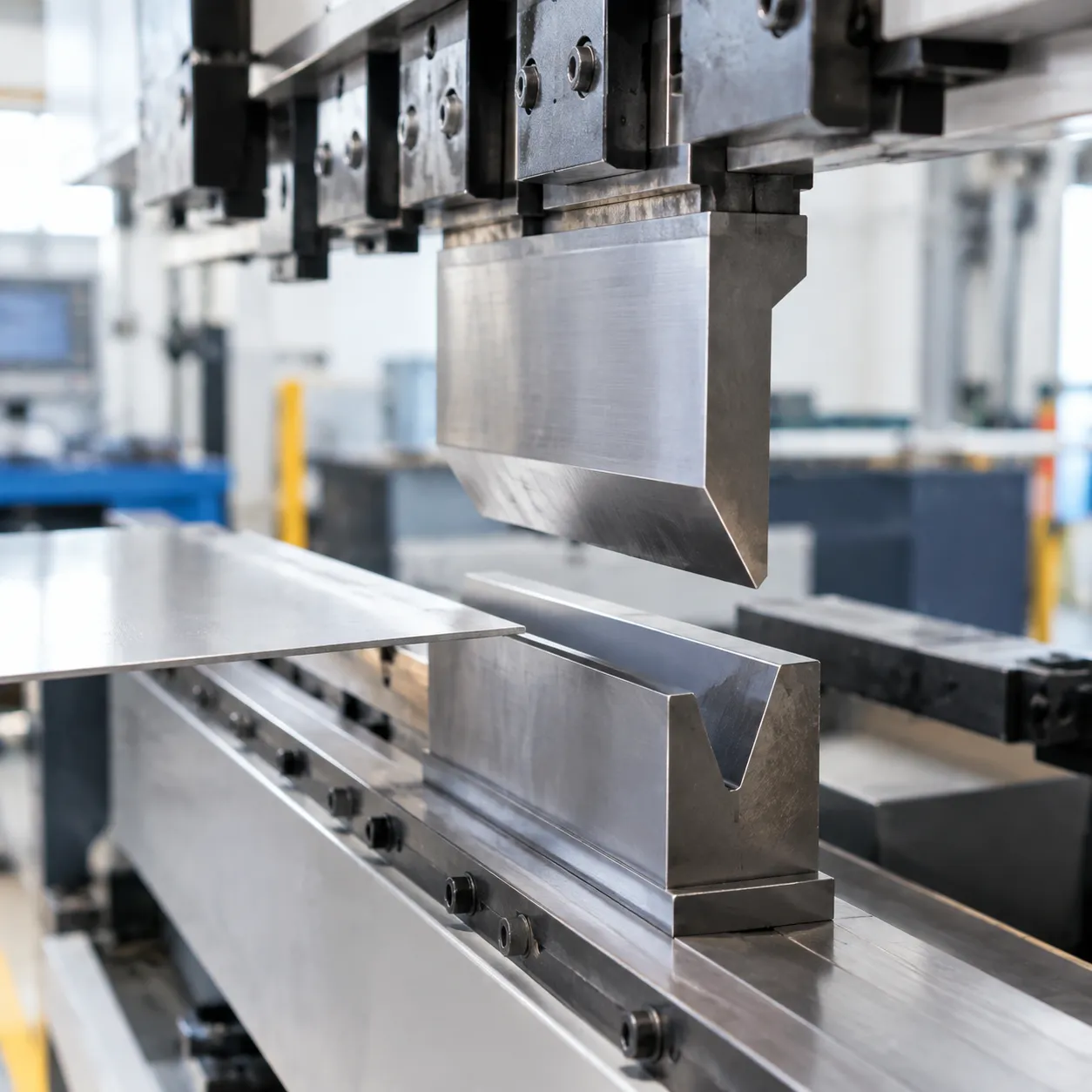
Material and Heat Treatment: 42CrMo Alloy Steel (HRC 47–53)
Die shoulder wear directly alters the effective V-width, leading to angle drift and surface marks on the workpiece. To prevent premature wear, our dies are manufactured with strict metallurgical standards:
- Core Material: Premium 42CrMo alloy steel for high tensile strength and resistance to cracking under heavy loads.
- Surface Hardening: CNC induction-hardened shoulders and contact surfaces reaching HRC 47–53, providing deep wear resistance against abrasive high-strength steels.
- Machining Accuracy: Precision-ground contact shoulders and V-grooves ensure exact tool centering across full lengths (835mm, 515mm, and sectional sets).
Tooling Form Factors for Fast Changeovers
Selecting the right die body format keeps machine downtime low when shifting between different sheet gauges.
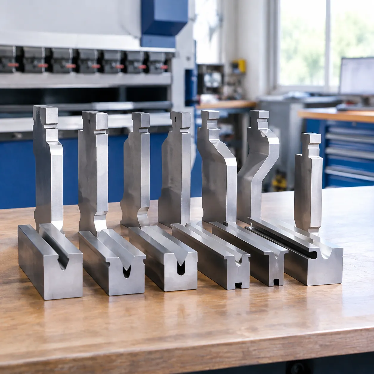
- Single-V Dies: Engineered for high-precision, heavy-tonnage applications and deep box bending where side clearance is critical. Explore our dedicated precision press brake V-dies for standard and acute jobs.
- Centered 2V Dies: Symmetrical double-groove designs that allow quick flipping between two distinct openings on standard European and Promecam-style clamping systems.
- Multi-V Die Blocks: Ideal for general fabrication shops handling diverse sheet ranges. Our heavy-duty multi-V die blocks enable rapid thickness changes from light gauge up to heavy plate without removing the tooling block from the bed.
Custom Die Profiles and Shoulder Geometries
Standard 90° dies do not fit every bending condition. We manufacture custom die profiles matching exact material yield strengths, springback tendencies, and flange clearance requirements.
| Profile Type | Included Die Angles | Typical Application | Shoulder Radius Design |
|---|---|---|---|
| Acute Dies | 30°, 45°, 60° | Deep air bending, pre-hemming, and high-springback materials | Standard tight radius or custom enlarged entry |
| Air Bending Dies | 85°, 88° | Standard air bending with built-in springback compensation | Smooth ground radius to eliminate drag marks |
| Heavy Plate Dies | 60°, 75°, 80° | Thick plate and high-tensile structural steel | Large-radius shoulders (R3 to R15+) to prevent plate cracking |
Technical Review and Custom Tooling RFQ Workflow
When selecting an air bending bottom die opening for 2 thick materials—whether sizing a 16mm V-opening for 2mm sheet metal or scaling up to large openings for heavy 2-inch structural plates—our engineering team verifies your setup parameters before production:
- Application Audit: You supply material grade, yield strength, sheet thickness, target inside radius, and minimum flange requirements.
- Tonnage & Sizing Validation: We calculate required bending tonnage per meter, confirm shoulder friction limits, and verify machine bed compatibility.
- Drawing & Tool Delivery: We provide complete CAD tool profiles and deliver precision-ground, heat-treated dies built directly to your machine's clamping standard.
Frequently Asked Questions About Air Bending Bottom Die Sizing
What is the ideal bottom die opening for 2mm stainless steel vs. 2mm mild steel?
For standard 2mm mild steel, the industry standard baseline is a 16mm bottom die opening (8xT). This provides a balanced tonnage load, reliable angular control, and an inside bend radius of roughly 2.5mm to 2.7mm.
When running 2mm stainless steel (such as 304 or 316), the yield strength is significantly higher. We recommend opening up the die width to 20mm (10xT) using precision-ground press brake bottom dies. This adjustment lowers required machine tonnage, minimizes galling on the die shoulders, and prevents surface strain cracking along the outside radius.
How do I calculate the minimum flange length for a specific V-die opening?
To prevent the workpiece from slipping into the die cavity during the stroke, use the standard minimum flange formula:
- Standard Rule: Minimum Flange Length = 0.7 × V to 0.8 × V (measured from the outside edge).
- Example for V = 16mm: Minimum Flange = 16mm × 0.7 = 11.2mm.
- Example for V = 12mm: Minimum Flange = 12mm × 0.7 = 8.4mm.
If your part design features a flange shorter than 0.7x of the die opening, the material will fall across the die shoulders before reaching full pinch, resulting in ruined parts and severe operator hazards.
Can I use an 8xT die opening for heavy plate over 12mm thick?
We do not recommend running an 8xT ratio on heavy structural plate. Heavy plate has lower elongation and high grain resistance. Applying an 8xT opening creates extreme tonnage spikes, risks chipping the punch tip, and frequently causes the outer bend radius to rupture or crack.
For plates 12mm and thicker, scale the die selection to 10xT or 12xT using heavy-duty multi-V material bending blocks with large, smooth shoulder radii.
How does changing the bottom die opening affect springback in air bending?
In air bending with press brake bottom die opening systems, the inside bend radius naturally floats to approximately 15% to 17% of the die width ($R_i \approx V / 6$).
- Wider V-Opening: Produces a larger inside radius, expanding the elastic deformation zone and increasing angular springback (requiring deeper stroke penetration or acute dies like 85° or 88° to compensate).
- Narrower V-Opening: Forces a tighter inside radius, concentrating plastic deformation and reducing springback, but at the cost of significantly higher tonnage per meter.
What happens if the punch tip radius is larger than the natural air bend radius?
When air bending, the inside radius normally forms freely based on the V-die width. However, if the punch nose radius is larger than the natural float radius (R_p > 0.16 × V), the sheet conforms directly to the punch geometry.
This increases the contact area, alters the natural leverage of the die shoulders, raises required forming tonnage, and invalidates standard bend deduction tables unless reprogrammed for the larger radius.