Are you chasing bend angle inconsistencies across a long sheet metal part, ready to grab a stack of feeler gauges to fix the issue? Before jumping straight into how to properly shim an air bending press brake die, we always run through our standard pre-shimming checklist. Attempting to shim over worn tooling, incorrect die selections, or dirty bed rails only masks underlying mechanical issues and drastically increases press brake bed deflection.
Pre-Shimming Inspection Checklist
At CAMT, our engineering standards require verifying three core baseline parameters before placing any shim stock under a lower die:
- Inspect Tooling Surface & Hardness: Verify that lower V-die working edges retain original precision profile tolerances within ±0.01 mm and maintain deep induction hardening integrity (HRC 55–60). Physical wear on the V-groove shoulders creates artificial angle variances that shimming cannot permanently fix.
- Validate V-Opening Selection Rules: Ensure your lower die selection matches the sheet metal material thickness ($T$):
- Standard Mild Steel: $V = 8T$
- Thin Gauges / Tight Radii: $V = 6T$
- Heavy Plate / High-Tensile Stock: $V = 10–12T$
- Note: Using an undersized V-opening artificially inflates tonnage demand per foot, severely exaggerating bed deflection and forcing unnecessary shimming.
- Clean Seating Surfaces: Thoroughly remove all mill scale, metal chips, burrs, and rust-protective oils from the lower die rails and machine bed. Contact surfaces must be completely clean, targeting a surface roughness of Ra < 0.8 µm to guarantee flat, stable seating.
Step-by-Step Execution: How to Shim an Air Bending Lower Die
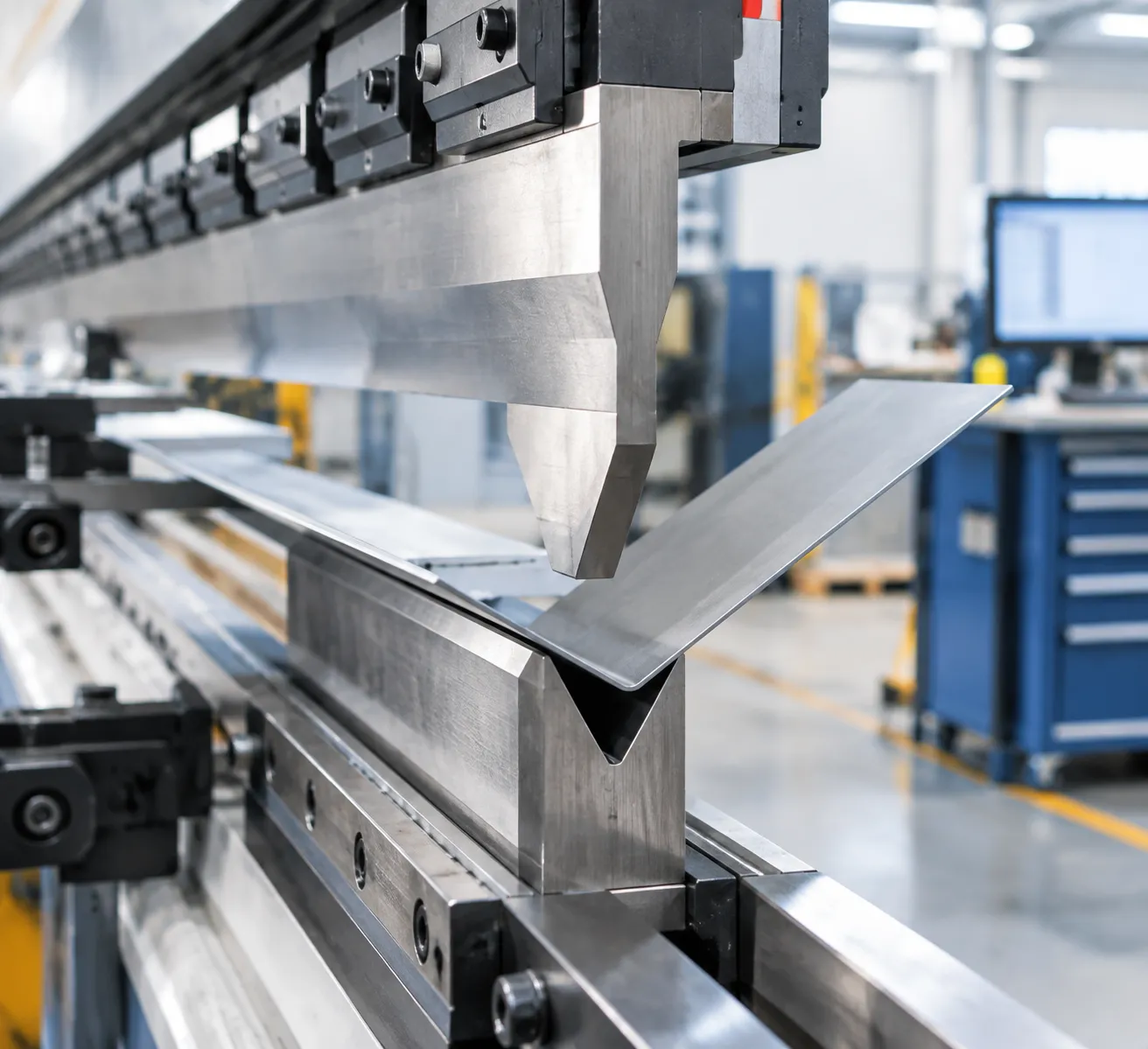
Knowing how to properly shim an air bending press brake die fixes the "boat hull effect" and delivers uniform bend angles across your entire sheet length. We follow this precise 5-step execution process on the shop floor:
Step 1: Run Full-Length Test Bend & Check 5 Points
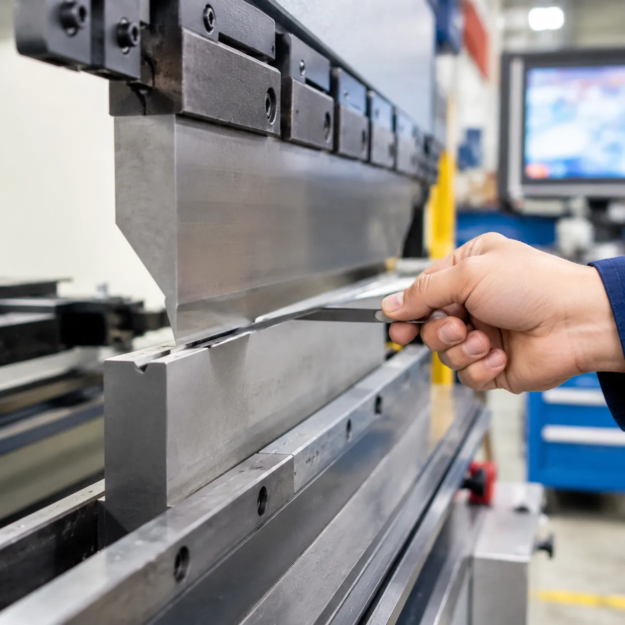
Execute a test bend across the full length of your stock. Use digital protractors to measure and record inside bend angles at 5 critical checkpoints:
Left End
Left-Center
Center
Right-Center
Right End
Step 2: Calculate Angular Deviation & Shim Height
Determine the variance between the open center and closed outer ends. Use our standard shop rule of thumb:
Every 0.002 in (0.05 mm) of vertical shim height yields approximately 1° of bend angle correction.
Calculate the exact elevation needed at each measured checkpoint to level out the angular profile.
Step 3: Select Precision Shim Material
Avoid paper, brass, cardboard, or aluminum scrap—these soft materials compress under tonnage load and trigger unpredictable sheet metal bend angle variance.
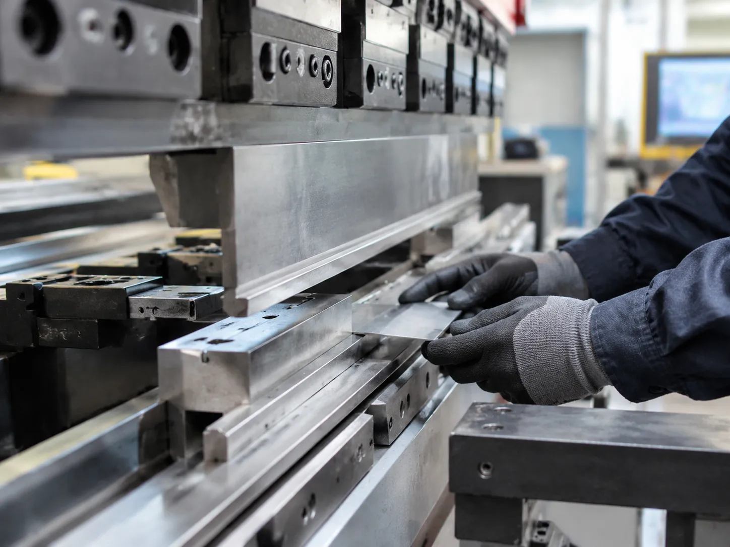
Use only certified cold-rolled feeler gauge steel shim stock or precision ground steel shims.
High-density steel shims hold strict vertical tolerances under high load, especially when setting up heavy-duty tools like a 50-ton press brake die kit.
Step 4: Pyramid Layer Shims Along Die Centerline
To match the machine bed's natural parabolic deflection curve:
Lay a single long shim along the central low-deflection zone.
Stack progressively shorter shims toward the exact center point to build a balanced pyramid structure.
Maintain strict lower die seat centerline alignment so the V-groove stays perfectly centered with the punch.
Step 5: Secure Clamps & Verify Bend Precision
Torque all lower die holder clamps evenly across every section to avoid localized stress points. Run a second test sheet to confirm angle uniformity across the entire bend within our baseline ±0.01 mm precision. If angles remain inconsistent, consult our press brake V-die lifespan guide to evaluate whether severe working edge wear requires regrinding.
Avoid Major Mistakes: How to Properly Shim an Air Bending Press Brake Die
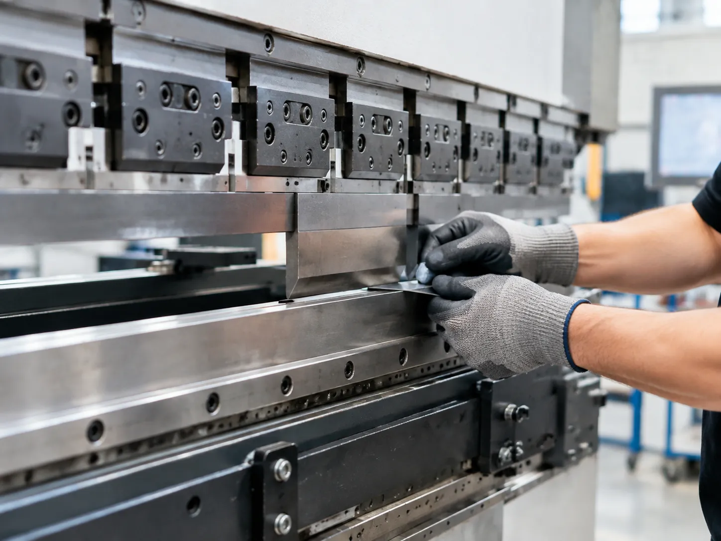
Common Shimming Pitfalls & Technical Risks
| Error | Root Cause | Impact & Consequence |
|---|---|---|
| Point-Loading | Over-shimming narrow areas instead of tapering the shim profile | Severe stress concentration, permanent bed deformation, lower die base cracking |
| Centerline Misalignment | Placing shims unevenly across the die shoulder or bed slot | Shifts lower die seat centerline alignment, leading to tool tipping, side-load wear, and flange distortion |
| Confusing Deflection with Springback | Shimming the die to compensate for sheet metal batch variations | Inconsistent bend angles, ruined shim stacks, and unnecessary teardowns |
Key Risks to Avoid on the Shop Floor
- Tooling Rail Point-Loading Risks: Stacked, narrow shims focus high tonnage onto a tiny surface area. Exceeding your machine's rated tons-per-foot limit will crack the lower die or gouge the bed. Applying practical press brake die maintenance tips prevents localized overload and extends tooling life.
- Punch and Die Misalignment: Off-center shim placement throws off the alignment between your top punch and female press brake v-die. This creates severe side-thrust forces and inconsistent flange dimensions during sheet metal air bending.
- Misinterpreting Material Yield Strength: Never adjust shims to solve angle variances caused by heat-lot tensile changes. Physical bed flex requires height adjustment; material variations require material springback compensation made directly via punch depth controls on your CNC console.
High-Precision Tooling vs. Manual Shimming
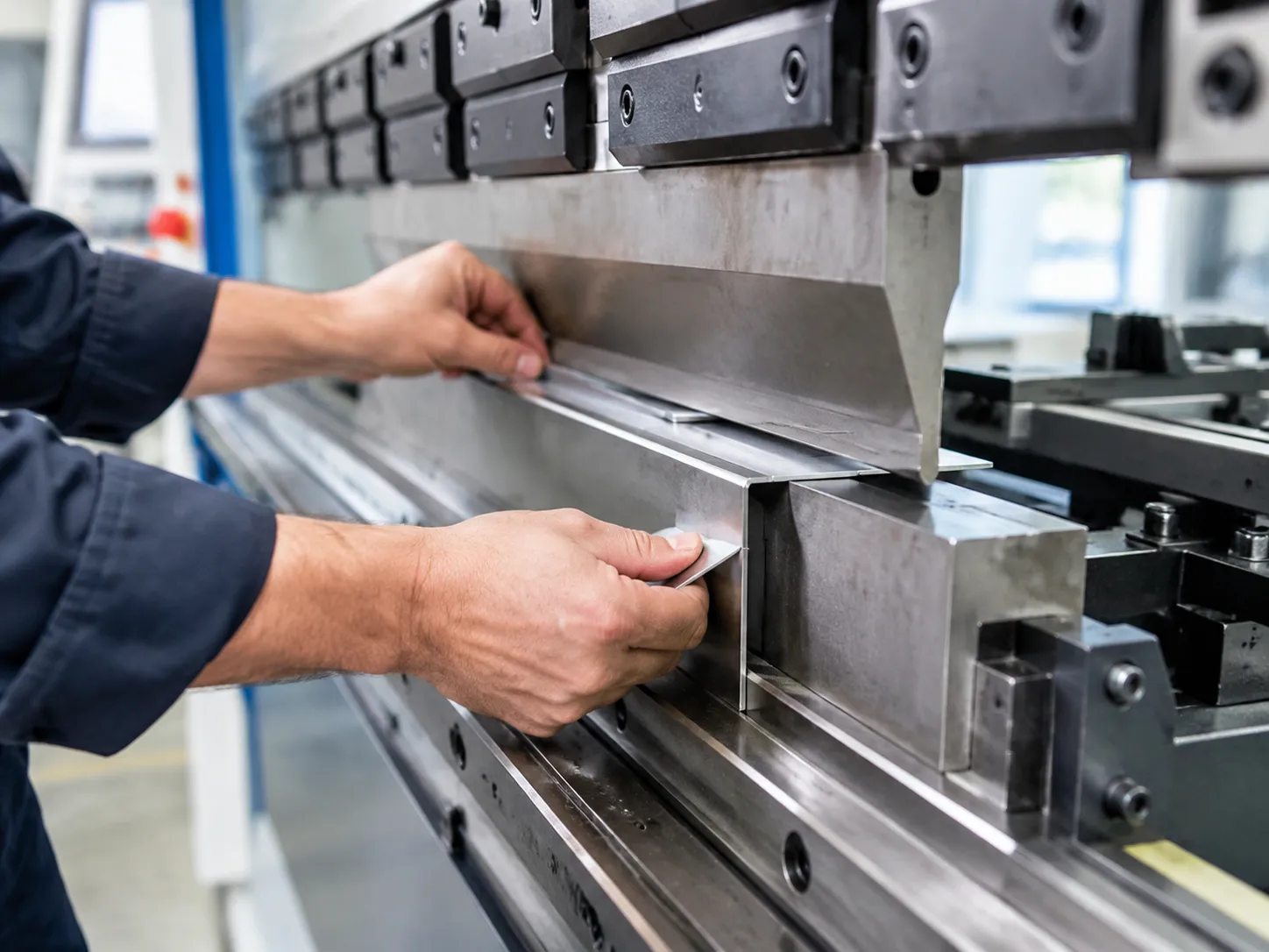
Manual shimming solves machine bed deflection, but relying on it to fix worn-out tooling eats up valuable shop floor time. Knowing how to properly shim an air bending press brake die starts with separating natural machine flex from degraded tools.
How Precision Tooling Minimizes Manual Shimming
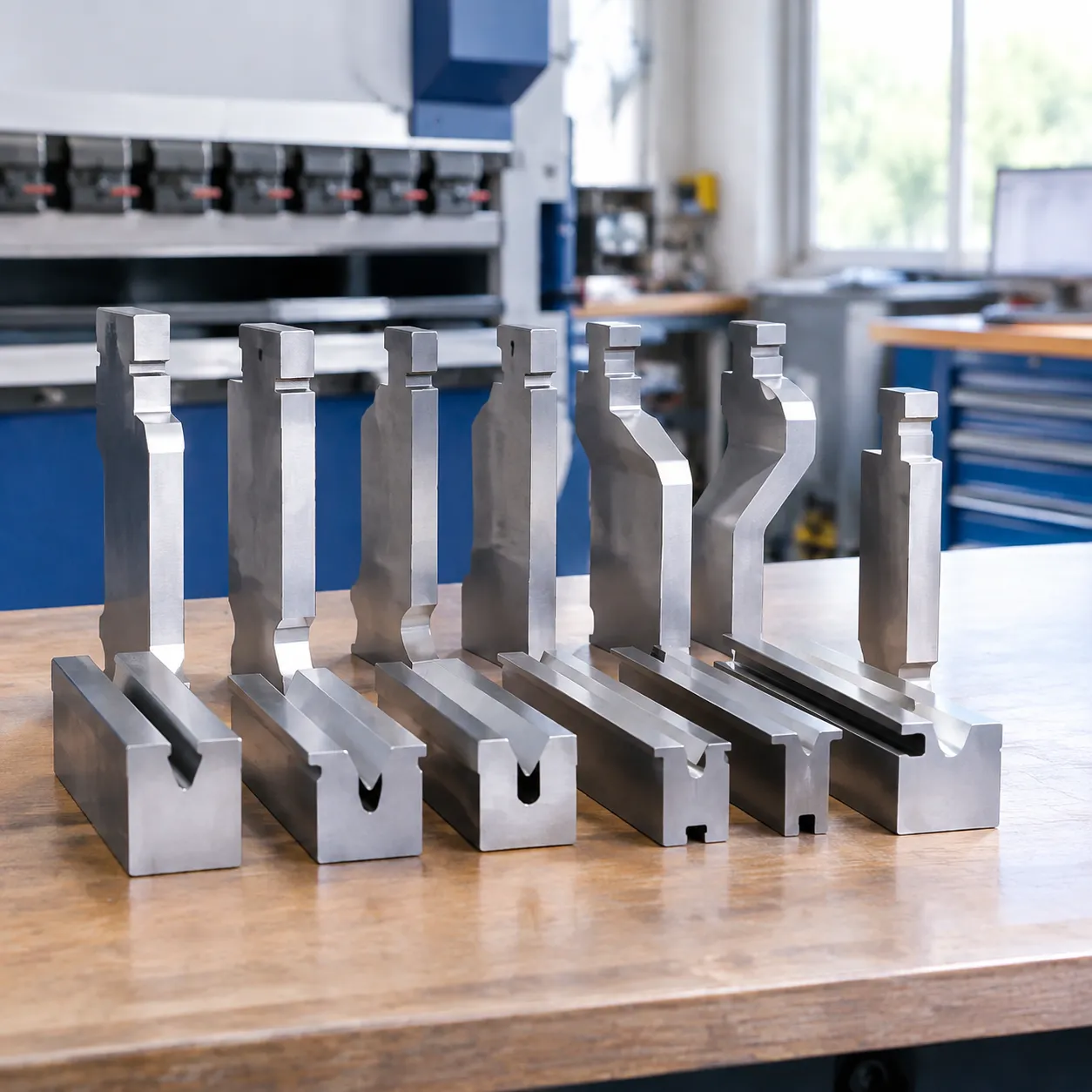
We cut setup times drastically by building baseline accuracy directly into the tools. High-precision CNC-ground tooling manufactured to tight ±0.01 mm tolerances ensures uniform height across long tool trains.
- Deep Vacuum Heat Treatment: Standardizes core hardness (HRC 55–60), preventing localized seating depression under heavy tonnage.
- Eliminated Tolerance Stack-Up: Precision grinding means multi-piece tool trains match perfectly, eliminating the need to shim out manufacturing variances between individual segments.
- System Consistency: Upgrading to precision-ground Wila tooling or Trumpf tooling systems keeps your working height identical across every setup.
When to Shim vs. When to Re-Ground or Replace
Shimming compensates for temporary frame deflection—it does not repair worn equipment. Layering feeler gauge stock over permanently damaged dies creates dangerous point-loading risks and ruins bend consistency.
| Decision Factor | Manual Shimming | Re-Grinding or Replacement |
|---|---|---|
| Primary Root Cause | Parabolic bed deflection under tonnage | Permanent tool wear or localized pitting |
| Variance Limit | Temporary adjustment up to 0.015 in (0.38 mm) | Surface wear exceeding ±0.01 mm tolerance |
| Setup Impact | Requires test bends and pyramid layering | Instant drop-in alignment with zero shimming |
| Operational Risk | Minor setup delay if done correctly | Die cracking, tool tipping, and flange distortion |
When die working surfaces show localized height drops beyond ±0.01 mm, stop layering shims. Send the section out for professional re-grinding or swap in new hardened tooling to protect your press brake bed and keep bend angles tight.
Air Bending Die Shimming FAQs
How does V-opening size impact machine deflection and shimming needs?
Smaller V-openings exponentially increase required bend tonnage because force requirements are inversely proportional to V-groove width. Forcing heavy stock into a tight V-opening artificially spikes tonnage demand, driving higher frame deflection and forcing you to use thicker shims to level out the bend angle. Following proper press brake die selection rules keeps tonnage requirements manageable and minimizes manual setup adjustments.
Should I shim under the lower V-die or under the press brake die holder rail?
We always recommend placing shims under the die holder rail rather than directly under a narrow V-die tang. Shimming under the rail distributes tonnage over a much broader surface area, preventing localized point-loading risks and helping maintain lower die seat centerline alignment across the entire bed.
What is the maximum thickness of shims I can safely use on an air bending die?
Keep total shim stack thickness under 0.015 in to 0.020 in (0.38 mm to 0.50 mm). If correcting sheet metal bend angle variance requires more elevation than this, stop shimming. Exceeding this threshold compromises tool stability; at that point, you need mechanical crowning compensation or sectioned tooling replacement.
Can improper shimming invalidate machine tonnage limits?
Yes. Off-center or localized shimming concentrates the machine's bed force onto a small surface area. This point-loading can easily exceed your press brake's rated tonnage distribution per foot—risking permanent bed distortion or die cracking—even if the total machine tonnage reading stays well below maximum capacity. Review established tonnage safety guidelines for press brake tooling before running high-tonnage jobs on shimmed setups.