
Formula details
Product Details
Overview
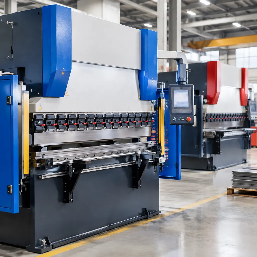
Understanding Press Brake Punch and Die Basics
What Is a Press Brake Punch and Die Set?
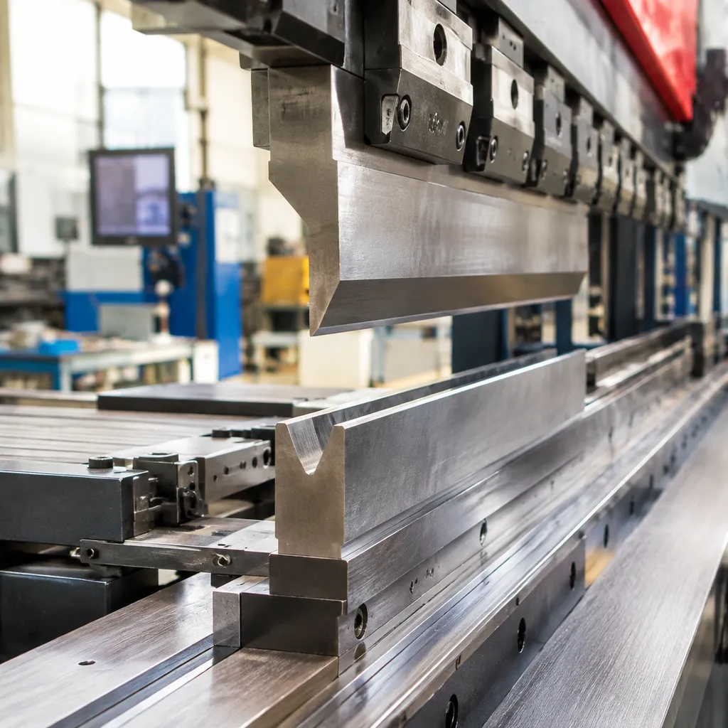
A complete press brake punch and die set consists of two matched components mounted to a hydraulic or electric press brake:
- Upper Punch: The male tool clamped to the machine's moving upper beam (ram) that forces material downward under tonnage.
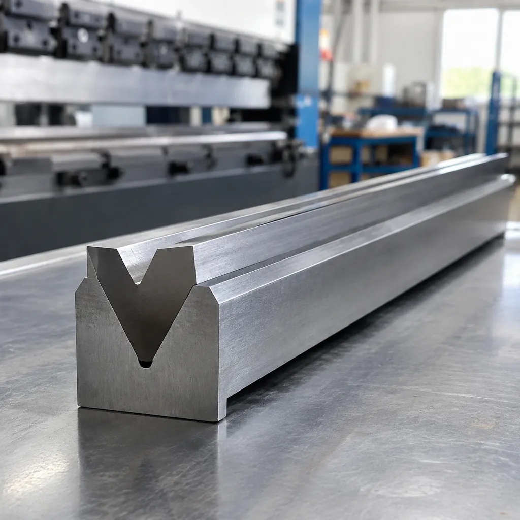
- Lower V-Die: The female stationary block seated in the machine bed that supports the sheet edges and dictates the bend geometry.
We design and configure these matched press brake dies and punch combinations to handle everything from thin gauge aluminum to high-tensile structural steel without tool deflection.
How Upper Punches and Lower V-Dies Interact During Sheet Metal Bending
The bending process relies on precise geometry rather than brute force alone. Here is how your punch dies press brake components interact under load:
- Material Positioning: The sheet rests flat on the lower die shoulders, registered against automated backgauges.
- Contact and Penetration: The upper punch descends, making initial center-line contact with the sheet surface.
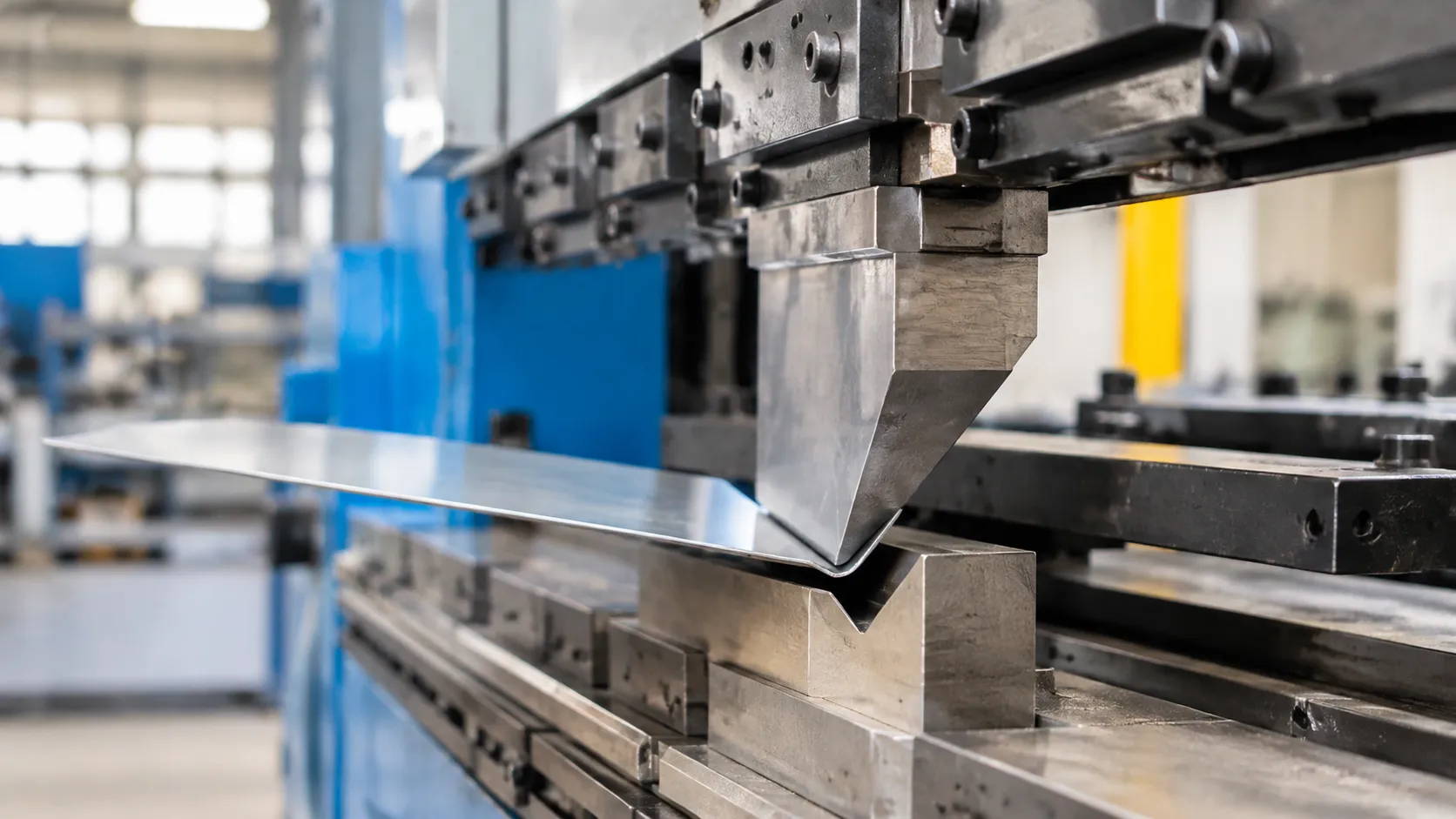
- Three-Point Contact Bending: In air bending, the sheet makes contact at only three points—the punch tip and the two die shoulders. The punch forces the material into the open space of the die cavity without hitting the die bottom.
- Elastic Recovery (Springback): Once the punch retracts, the bent sheet partially springs back. We account for this by overbending using acute punch and die profiles to achieve accurate final parts.
Key Components: Punch Tip Radius, Shoulder Radius, and V-Groove Width
Every press brake die and punch set depends on three critical dimensions that govern bend quality, tonnage requirements, and material integrity:
| Geometry Feature | Role in the Bending Operation | Practical Rule of Thumb |
|---|---|---|
| Punch Tip Radius ($R$) | Dictates the inside radius of the finished part and concentrates tonnage. | Must not be smaller than the material's minimum natural bend radius to prevent line fracture. |
| Die Shoulder Radius ($r$) | Smooths material flow into the V-cavity and reduces friction/galling. | Larger, hardened shoulder radii reduce drag marks and lower the required bending tonnage. |
| V-Groove Width ($V$) | Establishes the span between support points during the bend cycle. | Standard baseline: use 8 × sheet thickness for mild steel up to 1/4 inch (6 mm). |
Selecting the proper balance among these three parameters prevents premature tool wear, eliminates part marking, and ensures every stroke delivers the exact angle your drawing requires.
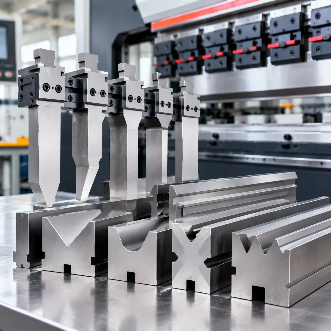
Common Types of Press Brake Punches
Standard Straight Punches for 90-Degree Bends
Standard straight punches are the primary workhorses for everyday sheet metal forming. Built with direct vertical load transfer, they handle high tonnage without deflection.
- Primary Use: Simple single bends, large panels, and open 90-degree profiles.
- Key Strength: Maximum rigidity and high tonnage resistance.
- Limitations: Poor clearance for return bends or narrow channels.
For clean, single-hit parts, running standard 90-degree press brake tooling for precise bends maintains consistent angle repeatability across full sheet lengths.
Gooseneck Punches for Channels and Box Profiles
When forming U-channels, deep boxes, or parts with return flanges, standard punches crash into pre-bent legs. Gooseneck punches feature a deep, recessed throat that provides clearance for previous bends.
- Primary Use: Deep box forming, secondary return flanges, and narrow U-profiles.
- Clearance Advantage: The relief cavity allows the return flange to swing inward without colliding with the tool body.
- Tonnage Warning: Because the load axis is offset, gooseneck punches have lower maximum load ratings than straight punches. Always verify your machine tonnage chart to prevent tool fracture.
Acute Angle Punches for Tight Bends and Pre-Hemming
Acute angle punches feature narrow tool tips ground from 28 to 60 degrees. They provide the tip clearance needed to bend past 90 degrees, which is critical for two primary jobs:
- Overcoming Springback: Bending high-strength steels or thick aluminum requires over-bending to allow the material to spring back into a true 90-degree square.
- Stage-One Hemming: Forming safe, crushed edges requires a sharp preliminary bend before flattening. Pairing acute profiles with dedicated hemming punches for precise sheet metal forming lets you complete acute air-bending and edge seaming in minimal steps.
Sash and Narrow Sword Punches for Tight Clearances
Sash punches (often called sword punches) feature an ultra-thin, elongated profile designed for tight clearances where conventional tools cannot reach.
| Punch Type | Typical Angle | Main Application | Load Capacity |
|---|---|---|---|
| Straight Punch | 85° – 90° | Flat sheet, basic brackets | High |
| Gooseneck Punch | 75° – 90° | U-channels, box profiles, deep return legs | Medium |
| Acute Punch | 28° – 60° | High-springback metals, pre-hemming | Medium to High |
| Sash / Sword Punch | 28° – 88° | Enclosed profiles, narrow seams, sash frames | Low to Medium |
Sash profiles solve clearance issues when working on window profiles, door frames, or narrow cross-sections with restricted return bends. Maintain exact alignment when loading sword punches to avoid side-load breakage under pressure.
Essential Types of Press Brake Dies
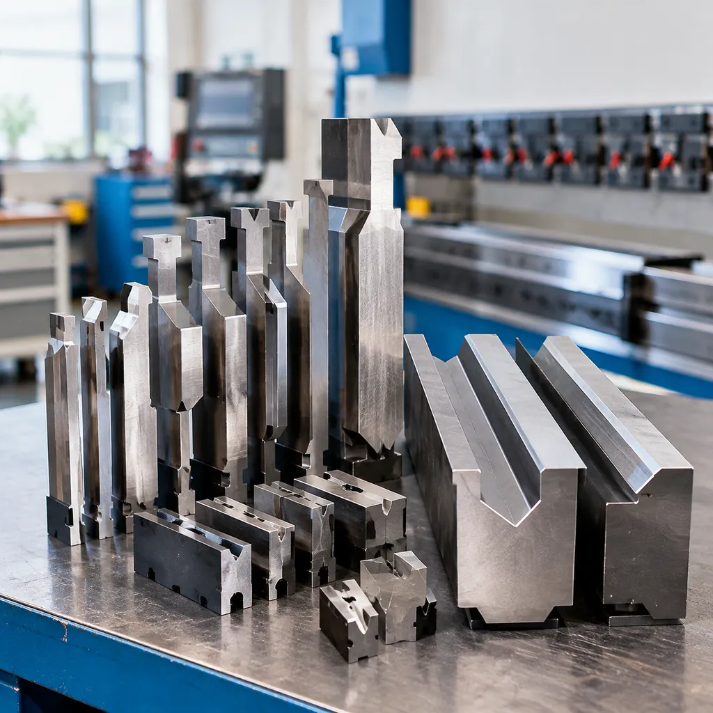
Choosing the right bottom die is just as critical as picking the right top punch. Your lower press brake die and punch setup dictates your bend radii, minimum flange lengths, and whether parts come off the machine clean or scratched up. We break down the standard die profiles we run on the shop floor every day to help you choose the best tooling for your production runs.
Single V-Dies vs. 2V Double Dies for Fast Job Changeovers
Single V-dies are the industry standard for dedicated CNC setups. Because they feature a single centerline, you lock them in once, dial in your backgauge, and run high-precision air bending jobs without re-centering.
When you switch between different sheet metal gauges throughout a shift, flipping tools wastes valuable time. That is where 2V press brake dies for precise sheet metal bending step in. These blocks put two distinct V-openings—often a small V for thin sheet and a larger V for heavier stock—on opposing sides of the same die body.
- Single V-Dies: Best for high-tonnage runs, deep box bending with high side walls, and dedicated production lines.
- 2V Double Dies: Flip the die 180 degrees in the holder to jump between materials without re-aligning your press brake punch and die from scratch.
| Die Type | Changeover Speed | Tonnage Capacity | Best Application |
|---|---|---|---|
| Single V-Die | Moderate (full tool swap) | High to Very High | Precision CNC runs, heavy plate, deep returns |
| 2V Double Die | Fast (180° rotation) | Medium to High | Job shops handling frequent gauge changes |
Multi-V Die Blocks for General Sheet Metal Fabrication Shops
If you run an older mechanical brake or a manual job shop handling everything from 20-gauge sheet to 1/4-inch plate, a multi-V die block is your workhorse. These solid square or rectangular bottom dies feature four or more different V-openings machined across their faces.
- Broad versatility: One block covers four to eight distinct V-groove opening widths.
- Cost savings: Eliminates the need to buy half a dozen dedicated bottom dies for one-off bends.
- Trade-off: Multi-V blocks are heavy to rotate and lack the precision ground centering shoulders needed for tight-tolerance automated CNC work.
Flattening and Hemming Die Sets for Clean Edge Seams
To eliminate sharp edges on sheet metal or build rigid double-layer edges on enclosures, you need a two-stage hemming operation. Using an acute top punch along with a specialized hemming die makes this process seamless:
- Stage 1 (Acute Pre-Bend): The sheet metal bending dies bend the edge to an acute angle between 28° and 35°.
- Stage 2 (Flattening): The spring-loaded bottom die shifts or a flat section closes down under tonnage to mash the acute bend flat into a finished Dutch or teardrop hem.
Spring-loaded combination hemming dies allow your operator to perform both operations in a single handling cycle without swapping out the press brake punch dies.
Non-Marking Urethane and Roller-Bearing Dies for Delicate Surfaces
Standard tool steel dies leave friction die marks and galling along the bend line as sheet metal drags across the V-shoulders. When forming mirror-finish stainless steel, pre-painted parts, or aerospace-grade aluminum, secondary polishing drives labor costs through the roof.
To eliminate surface marring completely, we rely on non-marking press dies for scratch-free metal forming.
- Roller-Bearing Dies: Replace static steel shoulders with hardened rotating rollers that rotate with the sheet, cutting down friction and lowering tonnage demands.
- Urethane Inserts and Pads: The punch forces the sheet into a dense polyurethane pad or V-insert, wrapping the metal cleanly around the punch tip without any metal-on-metal sliding contact.
Press Brake Punch and Die Mounts and Clamping Styles
Mounting compatibility dictates how fast your operators set up jobs and whether your bends hold tight tolerances. If a punch and die for press brake systems does not seat squarely against the beam, your flange angles will drift across the bend length. Selecting the proper clamping standard keeps your machine rigid, safe, and productive.
European Style (Amada-Promecam) Standards
European style tooling remains the global benchmark for precision sheet metal fabrication. These punches feature an offset safety tang that hooks into mechanical or hydraulic clamps, preventing heavy upper tools from dropping during setup.
- Mounting design: Punches feature a standard 8.4 mm wide safety tang with a retention groove, while the lower dies utilize a 12 mm x 20 mm centering tang.
- Clamping method: Manual wedge clamps, quick-action mechanical levers, or push-button hydraulic clamps.
- Key advantage: We rely on precision-ground European-style press brake tooling because individual segments self-align directly against the clamping bar without manual shimming.
American Traditional Tang-Style Tooling
American standard tooling utilizes a straight, centered 0.5-inch (12.7 mm) tang on both the upper punches and lower dies. Secured by setscrews running through a standard clamping bar, this style has powered fabrication shops for decades.
- Mounting design: Straight 0.500" x 0.750" tang centered directly on the tool body.
- Clamping method: Manual setscrews tightened against the tang shoulder, or upgraded mechanical safety bars.
- Best use: Shops running heavy-gauge plate or older mechanical and hydraulic brakes favor robust American-style press brake tooling for deep, structural bending runs where brute strength beats fast setup speed.
Wila and Trumpf Style Quick-Change Tooling
Modern high-mix, low-volume production requires instantaneous changeovers. New Standard (Wila/Trumpf) style press brake punch and dies seat vertically with push-button release pins rather than sliding horizontally from the side of the machine.
- Self-seating mechanism: Hydraulic or pneumatic clamping pins engage the tool's safety clicks, pulling the punch flush against the ram automatically.
- Extreme accuracy: Precision ground surfaces deliver working heights within ±0.0004 inches (±0.01 mm), eliminating test bends entirely.
- Safety features: Built-in mechanical safety pins support the full weight of the punch dies press brake tooling even if clamp pressure drops.
| Mount Style | Tang Dimension | Loading Direction | Alignment Accuracy | Best Application |
|---|---|---|---|---|
| European (Promecam) | 8.4 mm tang / 12 mm die tang | Horizontal or vertical slide | ±0.0008" (0.02 mm) | General sheet metal, precision enclosures |
| American Tang | 0.500" (12.7 mm) straight tang | Slide-in horizontal | ±0.0015" (0.04 mm) | Heavy structural plate, high-tonnage bending |
| Wila / Trumpf | Hardened safety click pin | Vertical drop-in / click | ±0.0004" (0.01 mm) | High-mix automated CNC bending, rapid setups |
Using Tool Adapters for Mixed Punch and Die Sets
Running multiple press brake die and punch styles across a diverse machine fleet does not mean replacing existing inventory. Precision tool adapters bridge the gap between incompatible beam designs and modern tooling profiles.
- Upper beam conversion: Bolt-on European-to-American or American-to-European upper adapters allow standard hydraulic rams to accept modern sectional tooling.
- Lower bed converters: Solid lower bolster adapters convert 12 mm European slots or wide multi-V beds into standard 0.5-inch channels or 2V self-centering holders.
- Tonnage derating: When using adapters to run mixed press brake punch and die sets, always derate the maximum bending capacity by 10% to 15% to compensate for added stack height and lateral flex.
How to Select the Right Press Brake Punch and Die
Matching Punch Tip Radius to Metal Thickness and Tensile Strength
Selecting an incorrect punch radius leads to fractured bend lines or inconsistent angles. If the punch tip is too sharp, it creases the metal like a knife edge, weakening the structural integrity. If it is too large, you fight excessive springback.
- Mild Steel: Match your punch radius roughly equal to sheet thickness (R ≈ T) for clean bends.
- Stainless Steel: High tensile strength demands a larger radius (at least 1.5× to 2× T) to stop the grain from tearing.
- Aluminum: Softer alloys crack along the bend line easily; avoid needle-sharp tips and opt for smooth, polished profiles.
Understanding how to select the right press brake punch radius keeps parts within tolerance without overworking the machine.
Calculating the Correct V-Die Opening Width Using the 8x Rule
The standard baseline for general fabrication is the 8x rule: the V-opening width (V) should equal eight times the material thickness (T).
- T < 3 mm: Use V = 6 to 8 × T
- T = 3 to 8 mm: Use V = 8 to 10 × T
- T > 8 mm: Use V = 10 to 12 × T to ease bending resistance
For thin sheets or tight flange requirements, consult our press brake V-die opening guide and selection tips to balance inner bend radii against minimum flange lengths.
Air Bending vs. Bottom Bending vs. Coining Tool Geometry
Your bending method determines the required geometry of the press brake dies and punch:
| Bending Method | Tool Geometry | Tonnage Required | Key Advantage |
|---|---|---|---|
| Air Bending | Acute punch (85 °, 88 °, 30 °) + matching die | Lowest (Baseline: 1×) | Uses one tool set for multiple angles; minimal tool wear. |
| Bottom Bending | Punch and die match the target angle (90 °) | Medium (3× to 4× air bending) | High angle repeatability with minimal operator intervention. |
| Coining | Sharp tip penetrates metal past yield point | Highest (5× to 8× air bending) | Extremely precise, but rapidly accelerates machine and tool wear. |
Tonnage Load Limits: Calculating Tonnage per Foot to Prevent Broken Tooling
Every punch and die for press brake operations carries a strict load limit stamped directly on the tool body. Never exceed the maximum tons per foot (or tons per meter) rating.
To estimate required air bending tonnage for mild steel:
Tonnage per Foot = (1.42 × Tensile Strength × T²) / V
- Check the tool shoulder load: Narrow V-dies concentrate force into very small contact areas, which can split bottom dies down the center.
- Check punch shank capacity: Long, narrow punches deflect under heavy loads and can snap at the relief neck.
- Spread the load: Always distribute high-tonnage forming over wider sections rather than concentrating force on short, segmented tooling.
Tool Steel Grades and Hardening Treatments for Press Brake Punch and Die Sets
The steel alloy and heat treatment behind your tooling determine whether your press brake punch and die holds tight tolerances for years or chips under the first heavy-tonnage job. We build and source press brake tooling to endure brutal cyclic loads, so choosing the proper base steel and surface hardening method directly protects your bottom line.
Top Tool Steels: 42CrMo, Cr12MoV, and T8A Compared
Not all tool steels handle bending stress the same way. The core must absorb heavy shock without snapping, while the working edges must resist intense abrasive friction.
| Steel Grade | Hardness (Core / Surface) | Toughness & Impact Resistance | Best Applications |
|---|---|---|---|
| 42CrMo (AISI 4140) | 28–32 HRC core / 55–60 HRC edge | Exceptional. High tensile strength and fatigue resistance. | The global standard for precision-ground press brake punch and dies, heavy plate bending, and high-tonnage forming. |
| Cr12MoV (AISI D2) | 58–62 HRC throughout | Moderate. Very high wear resistance, but more brittle under shock. | High-production stamping, acute-angle bottoming, and thin sheet runs requiring zero edge wear. |
| T8A (Carbon Tool Steel) | 48–52 HRC | Low. Budget carbon steel with limited shock resistance. | Light-duty sheet metal shops, short runs, and simple utility dies with low cycle demands. |
We rely on 42CrMo alloy steel as our frontline material. It delivers the ideal balance: a tough, shock-absorbing core that prevents catastrophic tool breakage, combined with edges that take heat treatment exceptionally well.
Deep Induction Hardening vs. Laser Hardening on Wear Edges
Precision tooling relies on localized hardening along high-wear zones—specifically the punch tip radius and the die shoulder radiuses.
- Deep Induction Hardening: We heat the working radiuses using high-frequency electromagnetic induction, followed by an immediate quench. This creates a hardened case depth of 2 mm to 4 mm at 55–60 HRC. It provides an ultra-durable wear buffer for heavy-duty fabrication and plate bending.
- Laser Hardening: A focused CNC laser beam heats the precise contact radius before self-quenching into the cold core. This method creates a shallower hardened zone (0.8 mm to 1.5 mm) but delivers zero thermal distortion along the punch profile. It keeps segmented punches and acute-angle dies straight to within microscopic tolerances.
Surface Coatings and Nitriding to Prevent Galling
Forming abrasive or sticky materials wrecks standard tooling edges. When bending galvanized sheets or running tough jobs like stainless steel processing, zinc flaking and material transfer cause rapid galling on your punch and die for press brake operations.
To eliminate scoring and pick-up, we apply specialized surface treatments:
- Gas or Plasma Nitriding: Infuses nitrogen into the outer 0.02–0.05 mm layer, boosting surface hardness up to 65–70 HRC (over 1000 HV). This drastically lowers the coefficient of friction, stops micro-welding, and prevents zinc buildup.
- PVD Hard Coatings (TiCN or CrN): Thin, high-density physical vapor deposition coatings create a slick, mirror-like barrier. They prevent edge drag and stop the sheet from scratching when working with mirror-finish stainless or decorative architectural panels.
- Black Oxide Treatment: A basic anti-corrosion finish applied to non-working surfaces to stop shop rust during storage, keeping segmented tooling rust-free and easy to slide into clamping bars.
Installation, Alignment, and Maintenance Practices for Press Brake Punch and Die Sets
Even the highest-grade press brake punch and die set will produce scrap parts if your setup, alignment, and care routines are sloppy. Proper installation keeps your bending tolerances tight, protects machine hydraulics from off-center loads, and prevents premature tool wear.
Step-by-Step Punch and Die Centering to Prevent Uneven Bend Angles
Misalignment between the upper punch tip and the center of the bottom V-groove causes severe angular deviation, uneven flange lengths, and heavy side-thrust that damages tool tangs.
Here is how we center a press brake die and punch set accurately:
- Clean the Surfaces: Wipe down the ram face, clamping bars, bed, and tool holders with a clean cloth. Any metal chip larger than 0.05 mm will throw your vertical centerline off.
- Mount the Tooling Loosely: Seat your bottom V-die firmly in the rail holder and lock the top punch loosely into the clamping system so it can still float slightly sideways.
- Engage Low-Tonnage Contact: Set your press brake to manual inching mode. Lower the ram slowly until the punch tip nests fully into the bottom V-groove with minimal pressure (around 2 to 3 tons total).
- Torque the Clamps Uniformly: With the punch fully seated in the die root, lock your punch clamps starting from the center and working outward to the left and right ends.
- Fasten the Bottom Die: Lock your lower die clamping screws sequentially to keep the punch and die press brake assembly locked on a single, true vertical centerline.
Diagnosing Machine Deflection and Crowning Issues Across Long Bends
When bending long sheets, it is common to see 90-degree angles on the outer edges while the center remains open at 92 or 93 degrees. This happens because the machine ram bows upward and the lower bed flexes downward under load.
| Symptom | Root Cause | Practical Fix |
|---|---|---|
| Open angle at center (canoe effect) | Machine deflection / under-crowning | Increase mechanical crowning wedge setting or adjust CNC hydraulic crowning pressure. |
| Over-bent center, open ends | Over-crowning | Back off the crowning compensation setting until the angle is uniform across the entire bend line. |
| Angle variations on short parts | Off-center tool wear or dirt under the die | Relocate short bends to different positions on the bed and check tool shoulders for localized gouges. |
Cleaning, Deburring, and Sectional Tooling Storage Habits to Extend Tool Life
Consistent upkeep directly determines your press brake punch and dies longevity and prevents expensive downtime. Implementing disciplined press brake die maintenance tips for longer tool life ensures your investment delivers hundreds of thousands of clean cycles.
- Stone Away Minor Burrs Immediately: Never use an angle grinder on precision-ground tools. Keep a medium-grit Arkansas or India stone by the machine to dress out minor micro-nicks caused by scale or galling.
- Keep Sectional Tooling in Matched Sets: Never mix segments from different manufacturing batches. High-precision sectional tools are ground together; scrambling them causes stepped witness marks on finished parts.
- Degrease and Apply Anti-Corrosion Oil: At the end of every shift, wipe down the working surfaces with a solvent to clear mill scale, then mist the tooling with a high-grade rust inhibitor.
- Store Tooling Vertically in Dedicated Cabinets: Avoid stacking bare punches on top of each other on wooden skids. Store punches and dies in partitioned drawers or polyurethane-lined racks to protect hardened tips and precision tangs from impact damage. Adhering to these handling standards directly supports your press brake V-die lifespan and bend count expectations across tough production runs.
Press Brake Punch and Die FAQs
We hear the same operational questions on the shop floor every week regarding setups, limits, and tooling wear. Here are direct answers to help you troubleshoot your press brake punch and die setups.
How do I choose the correct V-die opening for stainless steel?
For standard mild steel, we stick to the reliable 8 × material thickness rule. For stainless steel, you must increase that opening to 10× to 12× material thickness.
Stainless steel has significantly higher tensile strength and work-hardens rapidly during forming. Running stainless through an 8× opening spikes your required tonnage by 50% to 60%, drastically increasing the risk of fractured punch tips and galling on the die shoulders. Pairing your material with the right precision press brake V-die for accurate bending and increasing your opening preserves both the tool's radius and your machine’s hydraulic seals.
Can I mount European punches on an American style press brake?
Yes, but you cannot clamp them directly without an intermediate adapter.
- American Traditional: Features a 0.500-inch wide straight tang secured with horizontal set screws.
- European Style (Amada-Promecam): Features a notched safety tang designed for wedge-style mechanical or pneumatic clamping.
To run European tooling on an American beam, we install upper conversion adapters or quick-clamping bars. If you are upgrading older beds or mixing profiles, planning a press brake die replacement for American and European styles lets you standardize your entire punch and die press brake lineup without buying redundant sets.
| Tooling Mount | Tang Style | Clamping Mechanism | Direct Interchangeable? |
|---|---|---|---|
| American Traditional | 0.500" straight vertical | Horizontal set-screws | No (requires adapter) |
| European (Promecam) | Offset tang with safety lip | Wedge clamp / pull-up lever | No (requires adapter) |
| Wila / Trumpf | Safety click / pin system | Hydraulic or pneumatic pin lock | No (requires specific holder) |
Why does my punch tip crack or chip during bending?
Chipped punch tips point to excessive localized stress rather than defective tool steel. The most frequent causes include:
- Exceeding tonnage limits: Concentrating high tonnage on a narrow section (such as short punches under 100 mm) fractures hardened punch noses.
- Punch radius too sharp: Using a punch tip radius smaller than the natural inside bend radius of the sheet causes the punch to dig in like a chisel, wedging sideways load into the punch tip.
- Off-center loading: Forcing an acute punch off-axis or bottoming uneven sheet edges transfers lateral shear forces into the tip.
- Bending across cutouts or holes: When the bend line crosses a punched hole, uneven resistance knocks the punch tip sideways against the V-shoulder.
What causes angle variation from the center to the ends of the bend?
When a long bend is 90 degrees at the ends but opens up to 92 or 93 degrees in the middle, you are dealing with machine bed and ram deflection (the canoe effect).
Under load, the hydraulic cylinders push the ram down at the side housings, while the center of the upper ram flexes slightly upward and the center of the bed flexes downward. To fix this:
1. Engage and calibrate your machine’s dynamic CNC crowning system.
2. If running a manual machine, adjust the mechanical wedge crowning block under the lower rail.
3. For older beds without crowning, use specialized die shimming tape placed directly under the lower rail at the center of the span.
How many cycles should a precision-ground press brake die last?
A high-grade, precision-ground punch and die set manufactured from deep-hardened 42CrMo or Cr12MoV (55 to 60 HRC wear surfaces) typically delivers between 500,000 and 1,000,000 bending cycles under proper air-bending conditions.
Tool life shortens under specific conditions: bottoming or coining cuts tool longevity by more than half; bending mill-scale hot-rolled plate or abrasive metals accelerates shoulder wear; and running dirty, unlubricated stock causes micro-galling along contact shoulders within 150,000 cycles. Clean tooling and correct tonnage boundaries keep precision-ground press brake dies working within factory tolerances for years.