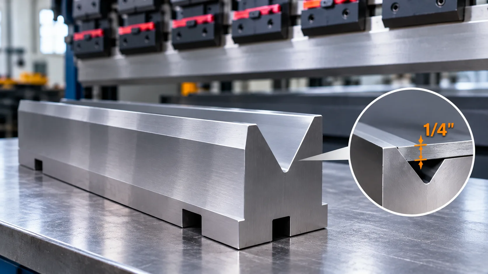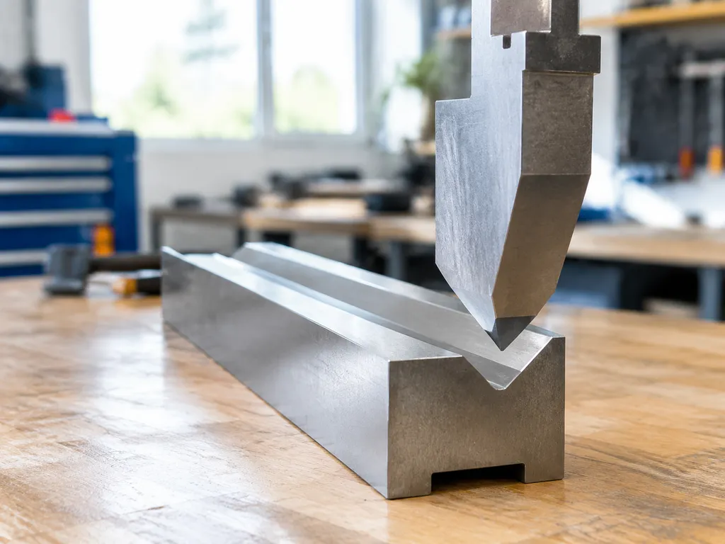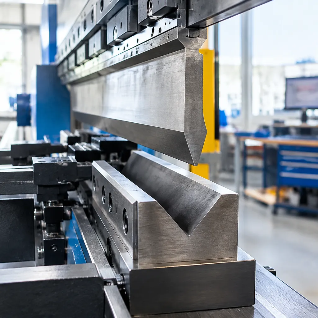

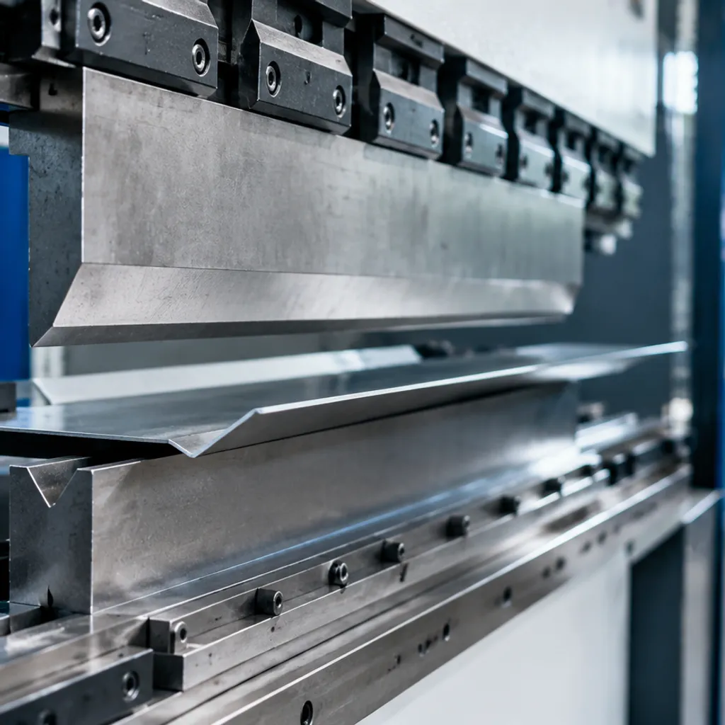
Anatomy of Trumpf Press Brake Tooling Systems
Precise trumpf press brake tooling adjustment starts with understanding how the tool mates with the machine beam. Trumpf-style setups eliminate traditional set-screw guesswork, relying instead on precision-machined contact faces and specialized clamping mechanisms to establish a rigid, repeatable working center.
Tang Profiles and Hydraulic Clamping Mechanics
The upper punch tang features a dedicated clamping groove tailored for either mechanical wedges or high-pressure hydraulic bladders. When you activate the press brake hydraulic clamping system, hardened clamping pins or continuous bars drive directly into the tang groove. This force pulls the punch upward instantly, seating it firmly against the beam receiver. Key structural mechanics include:
- Symmetrical tang geometry: Prevents lateral drift during engagement.
- Uniform clamping force: Applies equal holding pressure across the entire bend length.
- Zero tool drop: Holds the punch completely flush without manual pre-tightening.
Safety Click Operation and Lock Pin Seating
Vertical tool changes demand speed and operator safety. Trumpf punches use an integrated safety click mechanism—a spring-loaded mechanical lock pin embedded directly in the tang.
- Vertical Loading: Push the punch vertically into the upper holder. The pin retracts, passes the clamp lip, and snaps into the upper safety groove.
- Positive Retention: Even with hydraulic pressure completely released, the tool hangs securely and will not drop onto the lower die.
- Fast Release: A simple manual press on the safety button disengages the pin for rapid horizontal or vertical removal.
Shoulder-Bearing Load Transmission Mechanics
Precision air bending requires the tooling load to transfer through the correct physical surfaces. Trumpf-style punches are engineered as shoulder bearing tooling.
- Primary Load Bearing: Bending tonnage transmits straight through the precision-ground horizontal shoulders resting against the bottom face of the tool holder, not through the top of the tang.
- Tension-Only Tang: The tang merely locates and clamps the punch; it does not absorb vertical forming tonnage.
- Accuracy Protection: Direct shoulder contact prevents split holders, reduces tool fatigue, and keeps the tool tip on a strictly defined vertical datum under load.
Precision-Matched Segmented Punch Sets
When staging multi-bend stations or assembling split punches, height consistency across segments is non-negotiable. Modern segmented tooling setup practices depend on precision grinding:
- Matched Working Heights: Every segment within a set is ground to exact tolerances, ensuring the punch tip line remains dead flat across individual sections.
- Seamless Transitions: Eliminates differential loading between adjacent tools, stopping erratic angle shifts across long bending passes.
- Sectional Flexibility: Lets you configure custom tooling lengths in seconds without sacrificing overall centerline alignment.
Pre-Adjustment Cleaning and Machine Preparation
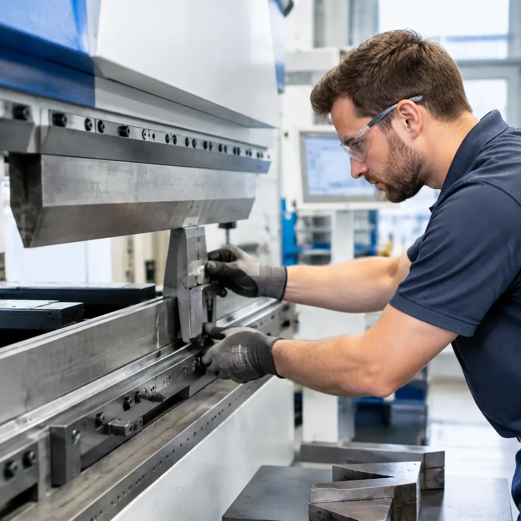
Before starting any Trumpf press brake tooling adjustment, we treat the machine bed and clamping beam as high-precision measuring surfaces.
Clearing Debris Under the 0.01 mm Tolerance Rule
Trumpf-style precision tooling seats on precision-ground shoulders. A single spec of mill scale or trapped metal dust measuring just 0.01 mm will tilt a punch or cock a die, introducing angular twist along your bend line.
- Stone the seating surfaces: Run an India stone lightly across the ram clamping groove, lower tool holder rail, and tool shoulders to remove micro-burrs.
- Solvent wipe-down: Spray degreaser and wipe the tang clamping areas completely dry using lint-free rags. Never leave wet oil films that attract abrasive airborne dust.
- Check the guide slots: Clean out the lower die rail to guarantee the V-die sits dead flat on its base datum.
Inspecting Punch Tips and V-Die Shoulder Wear
Never attempt tool centering on damaged profiles. We inspect every tool segment before placing it in the machine:
- Punch tip radii: Check for spalling, chipping, or micro-cracks along the tip with an optical loupe or radius gauge.
- V-die shoulder radii: Look for galling or longitudinal grooving. Uneven shoulder wear drags the sheet unpredictably, mimicking misalignment. Cross-check your tool profiles with our press brake V-die chart and tonnage guide to verify that wear has not compromised your load limits.
Checking Ram Datum Points and Backgauge Zero Positions
Tool alignment fails if the machine reference points are out of true. Before loading tools:
- Verify Y1 and Y2 datums: Confirm both hydraulic cylinders reach exact mechanical zero without differential readouts on the CNC.
- Calibrate backgauge fingers: Zero the X and R axes. Use a dial indicator against the backgauge stop fingers to confirm they run parallel to the lower rail datum line.
- Inspect finger faces: Ensure the mechanical stops show zero mechanical play and no surface denting.
Safety Setups and Slow-Jog Calibration Speeds
Never align tooling at full operating speed. Prepare the safety envelope before seating the steel:
- Switch to Setup/Jog Mode: Restrict ram descent to slow creep speed (typically under 10 mm/s) to avoid tool collision during the seating phase.
- Adjust mute points: Override normal fast-approach settings so the punch approaches the die strictly under controlled manual jog.
- Clear the operating area: Ensure all emergency stops, optical light guards, and foot pedal interlocks respond instantly before bringing the tooling faces together.
Step-by-Step Trumpf Punch and Die Alignment
Getting repeatable precision out of your brake comes down to mechanical discipline. A precise trumpf press brake tooling adjustment eliminates erratic flange lengths, stops tool-induced twist, and preserves your machine components over millions of cycles. When setting up punch and die sets, we follow a strict sequential workflow to seat, center, and lock the system into exact mechanical alignment.
Seating the Tang and Locking the Safety Click
Before engaging full clamping force, secure every upper segment firmly into the ram channel.
- Engage the safety mechanism: Push the tool straight up into the clamp until the spring-loaded safety click mechanism snaps into the upper retention groove. This prevents accidental drops during preliminary positioning.
- Inspect shoulder datums: Ensure the top reference shoulders of the punch seat squarely against the ground bottom face of the upper beam. We never rely on the tang tip to carry bending tonnage; the ground shoulders must absorb the full load.
- Verify lateral continuity: Slide adjacent segments tight against one another by hand. Look for any grit or burrs between segment faces that could create angular gaps before locking down the system.
Centering the Punch Tip in the V-Die Opening Under Light Tonnage
Eyeballing tool alignment leads to side-thrust wear and uneven part angles. We always use a low-tonnage mechanical centering sequence:
- Jog the ram down: Switch the machine to low-speed setup mode. Lower the upper beam until the punch tip just enters the V-die opening, stopping roughly 1 to 2 mm above the bottom radius.
- Loosen die rail fasteners: Release the lower tool holder rail locks just enough to allow the die block to float laterally.
- Apply seating tonnage: Jog the punch down into full bottom contact with the die shoulders under minimal tonnage (typically 3 to 5 tons per meter, never exceeding safe limits—refer to our European press brake die rating guide for tonnage safety to prevent tool overload). The downward force forces the die into true mechanical symmetry with the punch centerline.
- Lock the rail: Tighten the lower rail centering screws progressively from the center outward to secure the die position before raising the ram.
Activating Uniform Hydraulic and Mechanical Clamping Pressure
Once the tooling string is seated and centered, uniform clamping secures the setup against micro-shifting:
- Pressurize the clamping beam: Activate the press brake hydraulic clamping system. Ensure the clamping pressure gauge reaches the specified operating range (typically 280 to 300 bar on standard Trumpf/WILA systems).
- Check pin engagement: Visually confirm that every hydraulic clamping pin has driven forward, seating each individual tang directly against the upper horizontal reference datum.
- Tighten mechanical wedges: If running manual mechanical holders, torque the clamping screws evenly with a calibrated torque wrench to avoid uneven clamping force across the tool line.
Aligning Segmented Punches to Stop Witness Marks
Segmented tool runs require extra attention to prevent joint seams from marking your parts:
- Butt-joint alignment: When assembling segmented tooling setups, check that ground front faces sit flush with a precision straightedge. Even a 0.02 mm step between two punches will leave visible witness lines on sensitive sheet surfaces.
- Pre-clamp bridging: Clamp a flat ground steel rule across the V-die shoulders directly beneath the punch joints while cycling the clamp. This bridges the joint gap and pulls adjacent tool segments into exact horizontal plane alignment.
- Verify radius transitions: Inspect segment edges to confirm that the punch nose profiles match seamlessly across the bend length, keeping bend radii completely consistent across multi-segment folds.
Eliminating Frame Deflection and Crowning Errors
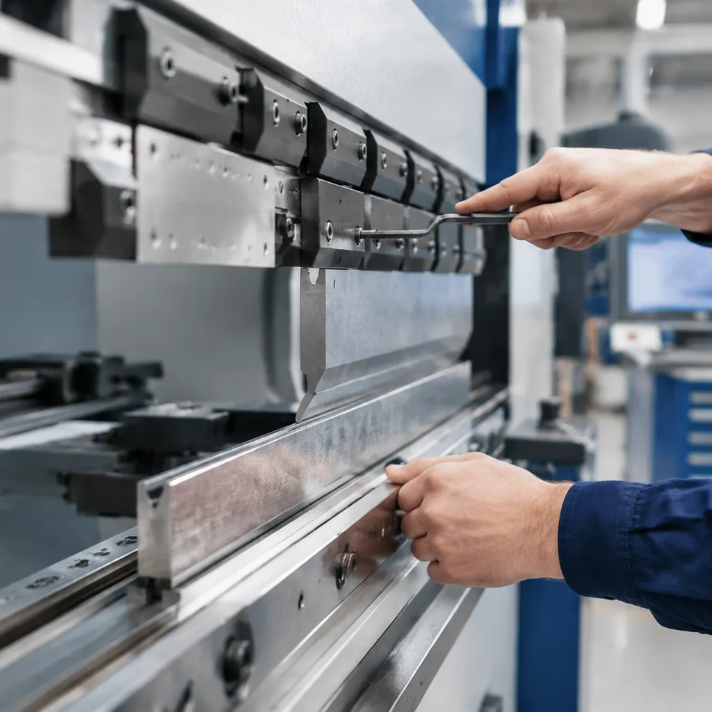
When bending long parts, frame deflection under load creates an uneven angle profile. Without proper compensation, parts end up overbent at the ends and underbent in the middle. Dialing in your trumpf press brake tooling adjustment requires setting up the machine bed compensation to match tool deflection and structural yield under target tonnages.
Diagnosing Center-to-Edge Angle Variance and the Canoe Effect
We see the "canoe effect" when the bed and ram deflect away from each other under load, leaving the center of the bend open:
- Symptom: Proper 90-degree bend at both ends, but 92 or 93 degrees in the middle.
- Root Cause: Natural machine bed deflection combined with punch penetration depth drop in the center span.
- Action: Check test bends with a digital protractor at five equidistant points along the bend line before adjusting crowning values.
Setting CNC Mechanical Wedges vs. Hydraulic Crowning Curves
Modern systems counter deflection through built-in compensation tables:
| Crowning Type | Operation Principle | Setup Rule |
|---|---|---|
| CNC Mechanical Wedges | Opposing dynamic wave-profile wedges shift laterally to form a true curve. | Input material tensile strength and thickness accurately into the controller to let the CNC calculate the required curve pitch. |
| Hydraulic Crowning Cylinders | Bed-integrated hydraulic cylinders push upward against downward ram force. | Match proportional valve pressure directly to the tonnage chart; verify cylinder seals if pressure drifts mid-stroke. |
For operations handling varying sheet thicknesses, using adjustable press brake dies for precision metal bending helps optimize bed-to-punch alignment while reducing frequent die swaps across different tonnage ranges.
Fine-Tuning Local Tx Micro-Adjustments on the Lower Rail
When running precision-ground tooling on a Trumpf-style lower rail, small angle anomalies can still pop up at specific points along the bed:
- Locate the Tx adjustment points: Inspect the set screws positioned at spaced increments along the lower tool holder rail.
- Loosen locking fasteners: Back off the lock nuts before applying torque to the adjustment screws.
- Dial in the localized height: Turn the local Tx screw clockwise to raise the lower die rail locally; counter-clockwise lowers it. A minor adjustment of 0.02 mm typically corrects an angular split of roughly 0.2 to 0.3 degrees.
- Re-tighten and re-verify: Lock the fasteners and run a test bend along the targeted zone.
Shimming Lower Dies for Asymmetrical and Deep-Box Bending
Off-center loading, stage bending, and deep-box clearance require targeted manual compensation when global CNC crowning cannot address localized loads. Pairing standard profiles with a dedicated CNC press brake die for precise metal bending ensures your foundation stays solid during heavy, localized air bending.
- Targeted Placement: Place precision steel shimming foils directly beneath the lower die sections that show underbending. Avoid stacking more than three foil layers under a single segment.
- Tapered Thickness: Step shims down in thickness (0.05 mm to 0.02 mm) outward from the low spot to create a smooth transition rather than an abrupt step.
- Safety Verification: Ensure the die tang remains properly engaged in the lower rail groove to prevent tool tilt when running asymmetrical bending programs.
Troubleshooting Common Trumpf Tooling Misalignment Faults
When precision parts start pulling out of square, standard trumpf press brake tooling adjustment routines will save hours of trial and error. We see the same tooling alignment and clamping errors hit the shop floor repeatedly. Here is how we isolate the mechanical culprits and correct them directly at the machine.
Fixing Angular Splits Between Y1 and Y2 Cylinders
An angular difference between the left and right ends of a bend usually points to ram tilt or uneven reference stops rather than bad tooling.
- Condition: A bend measures 90° on the Y1 side and 91.5° on the Y2 side across a single part.
- Root Cause: Uneven cylinder zeroing, loose mechanical scale encoders, or asymmetrical tool seating under load.
- Remedy: Jog the ram to bottom dead center without material. Verify that the tooling shoulder sits flush against the upper beam across the entire length. If the gap persists, run the CNC Y1/Y2 axis calibration cycle to re-synchronize cylinder depth. Never use crowning to fix a left-to-right angular split; adjust the cylinder offsets in the controller.
Stopping Bend Line Walking and Flange Drift
When flange lengths vary from piece to piece, the sheet is slipping or the tooling center has drifted off the backgauge reference line.
- Re-center the Punch and Die: Run a trumpf punch and die alignment check using precision alignment blocks. Lower the punch tip into the V-groove under 5% tonnage to eliminate lateral play before locking the lower rail.
- Inspect Die Shoulders: Worn or nicked V-die entry radii drag the sheet unevenly. Verify both entry radii with radius gauges.
- Square the Gauge Fingers: Confirm the backgauge R and X positions align parallel to the die centerline. If the sheet does not sit flat against the stop faces before the punch penetrates the V-opening, the bend line will walk.
Resolving Weak Hydraulic Clamping Pressure and Loose Punches
A punch section that drops, wiggles, or shifts under light handling indicates an issue within the press brake hydraulic clamping circuit.
- Pressure Drop Detection: Check the hydraulic pressure gauge on the clamping power unit. It must hold standard operating pressure without bleeding down.
- Bleeding Air: Air trapped in the upper tool clamping bar causes uneven pressure distribution. Bleed the clamping manifold at the end-of-beam ports until fluid flows free of foam.
- Debris in Tang Grooves: Dirt, dried coolant, or metal fines inside the upper receiver stop the safety pins from seating securely. Remove the tooling, depressurize the system, and clean the tang slots thoroughly. When working with hardened replacement Trumpf tooling, ensure the tang surfaces remain clean and dry to allow full mechanical locking.
Preventing Sheet Marking and Radius Galling
Galling and surface scratches ruin parts, especially on stainless steel or pre-painted aluminum runs.
| Fault Profile | Mechanical Cause | Shop-Floor Remedy |
|---|---|---|
| Flange Scratches | Severe friction at the V-die entry shoulder | Apply protective urethane tape over the die opening or switch to larger entry radii. |
| Centerline Score Marks | Nicked or chipped punch tips | Stone out burrs on the punch tip, or transition to dedicated radius punches designed for smoother material flow. |
| Material Pick-Up (Galling) | Dry metal-to-metal rubbing under high tonnage | Clean tooling radii and apply dry film lubricant or light forming oil along bend lines. |
Preventive Maintenance for Repeatable Tooling Setups
Daily Cleaning Protocols for Clamping Pins and Tool Tangs
Fine scale and oil residue build up quickly inside upper clamping pockets and lower tool rails. When contaminants settle between the tang and the clamping jaw, the punch cocks to one side, throwing off your angular accuracy.
- Wipe contact faces: Clear the upper clamping beam, tang surfaces, and safety-click slots with a clean rag and degreaser before every setup.
- Inspect pins: Ensure the spring-loaded lock pins retract smoothly and click out without binding.
- Clean lower rails: Blow out debris from the lower die pocket and dry-wipe the guide surfaces. Never let hard particles sit beneath the V-die shoulders.
Following standard press brake die maintenance tips for longer tool life keeps grit from embedding into precision-ground mating surfaces.
Checking Hydraulic Pressure Valves and Return Springs
A solid press brake hydraulic clamping system must deliver uniform force across the entire bed length. If line pressure fluctuates, segmented punches slip downward under load:
- Verify clamping pressure gauges: Check that the hydraulic circuit meets the manufacturer's specified working pressure during clamp engagement.
- Inspect mechanical return springs: Mechanical push-back springs must instantly kick the clamping bar open when released. Sticky bars cause uneven seating during your next tool swap.
- Look for valve leaks: Check hydraulic quick-disconnects and manifold seals along the upper beam for fluid weeping that leads to pressure drops.
Quarterly Beam-to-Bed Parallelism Verification
Tool adjustments cannot compensate for a misaligned press frame. Every quarter, we calibrate the physical relationship between the moving ram and the bed:
- Dial indicator sweeping: Mount a dial indicator to the upper beam and sweep the lower holder across the full Y1-to-Y2 travel. Parallelism must remain within tight tolerances.
- Backgauge zero checks: Recalibrate the backgauge fingers to the tooling centerline after verifying mechanical bed level.
- Check mechanical stops: Confirm that hydraulic cylinders deliver balanced mechanical travel to prevent uneven side-to-side tonnage loading.
Handling and Storage Practices to Protect Ground Shoulder Datums
Trumpf-style punches and dies transmit tonnage directly through their precision-ground shoulder datums. Once those shoulder edges nick or dent, consistent vertical seating is impossible.
- Never drag tooling on steel tables: Place punches and dies onto polyurethane mats, wood benches, or non-marring cart surfaces.
- Dedicated vertical racks: Store tooling vertically or on slotted shelving where ground tangs and shoulders never bang against adjacent segments.
- Apply corrosion inhibitors: Wipe clean tooling with a light machine oil film before rack storage to prevent surface rust and pitting on precision ground datums.
Frequently Asked Questions About Trumpf Tooling Adjustment
How often should you calibrate punch and die alignment on a Trumpf brake?
We check alignment at every major tooling changeover and verify it thoroughly at the start of each shift. A full Trumpf press brake tooling adjustment and centerline calibration should also be carried out immediately after any hard collision, over-tonnage incident, or when switching between radically different sheet thicknesses. Routine checks take minutes but prevent hours of scrapped parts.
What causes uneven clamping across segmented punches?
Uneven clamping typically traces back to three mechanical culprits:
Contamination: Slag, oil varnish, or metal chips trapped inside the upper clamping beam pockets.
Hydraulic pressure drop: Sticking mechanical pins or failing seals in the hydraulic clamping circuit that prevent uniform force across the entire beam length.
Mismatched tooling sets: Mixing worn punches with new segments. If shoulder-load heights vary by more than 0.01 mm, clamping force concentrates only on the tallest pieces, leaving adjacent segments loose.
How do you compensate for bend angle variation along long sheets?
When you see open angles in the center and tight angles near the side frames, you are dealing with bed deflection. We resolve this by tuning the machine's crowning curve:
Increase the CNC mechanical crowning value incrementally until the bend angle matches across the full length.
Verify material grain direction and yield strength consistency, matching your tooling setup to our press brake die angles guide for springback selection.
Inspect the lower tool rail for localized wear or debris under the die tangs before making permanent offset changes.
Can worn shoulder datums be re-machined or shimmed back to spec?
Shimming shoulder datums with brass foil can work as an emergency field patch, but we strongly advise against it for high-precision production. Shims compress unevenly under heavy loads, induce side-thrust, and ruin your punch-to-die centerline calibration. When load-bearing shoulders or V-profiles develop step wear, the reliable solution is utilizing precision press brake die resurfacing services to grind both shoulders and tang datums back to uniform factory tolerances.