Formula details
Product Details
Overview
What Are Press Brake Bottom Dies and How Do They Work?
Definition and Core Function in Sheet Metal Fabrication
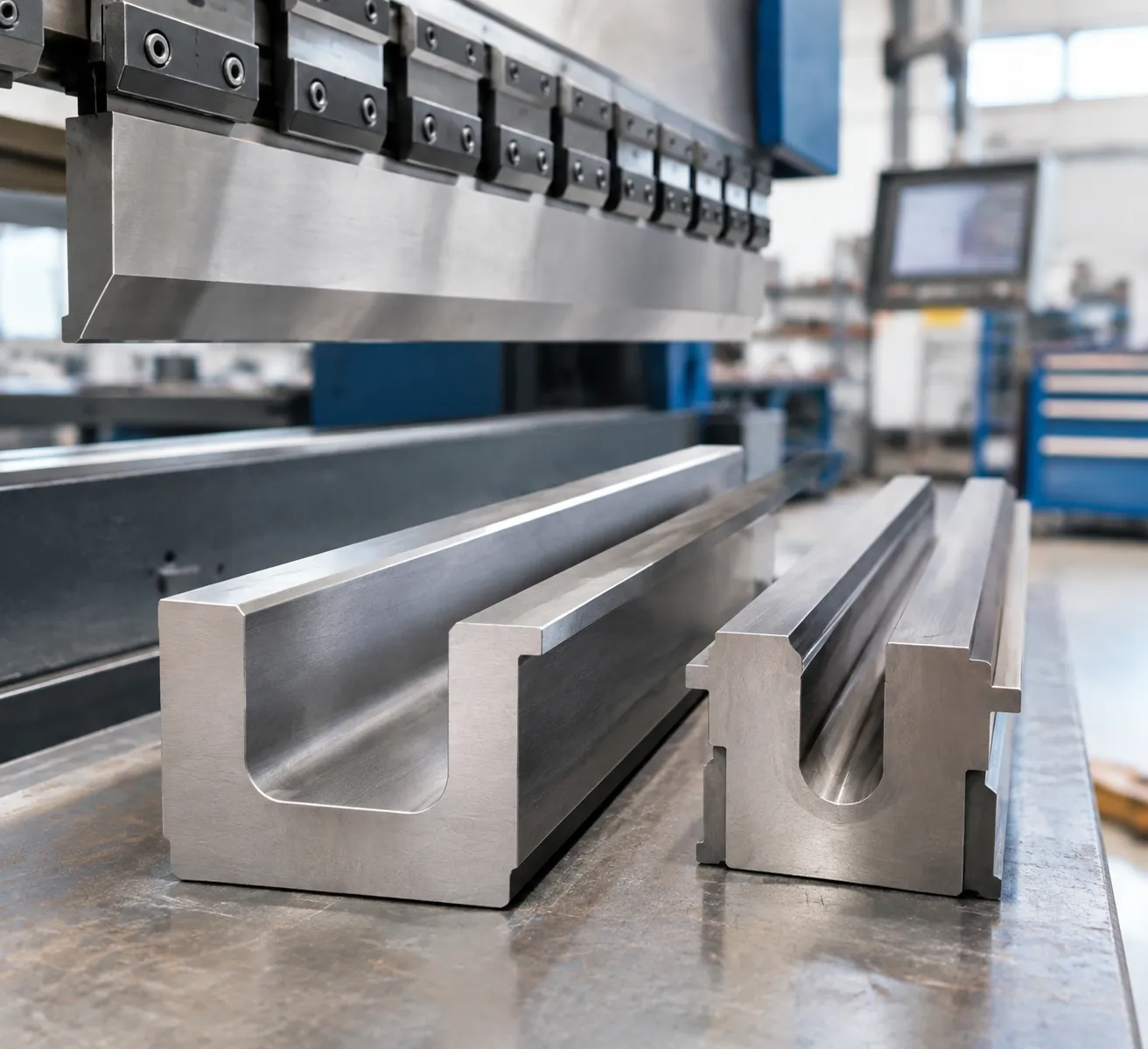
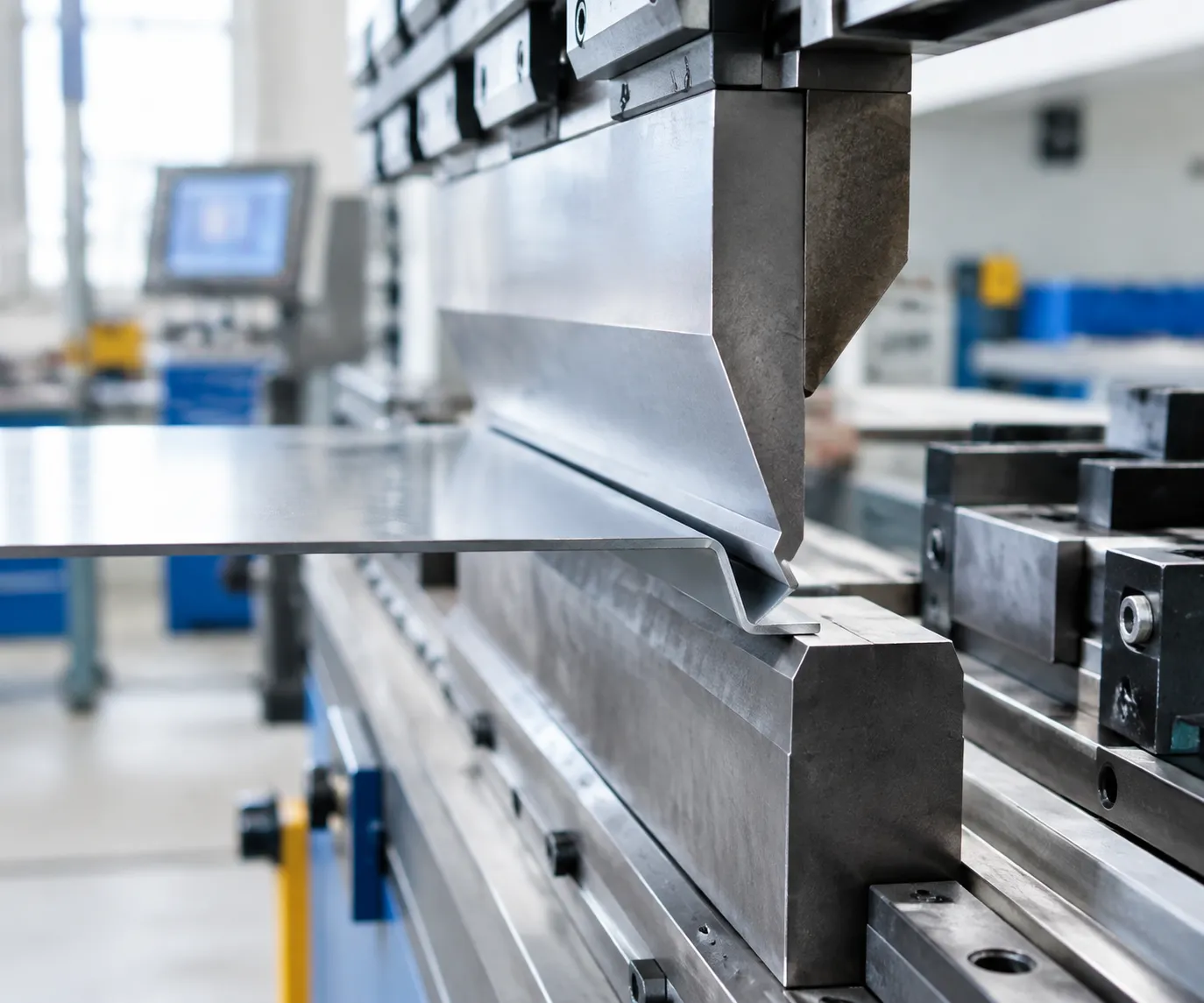
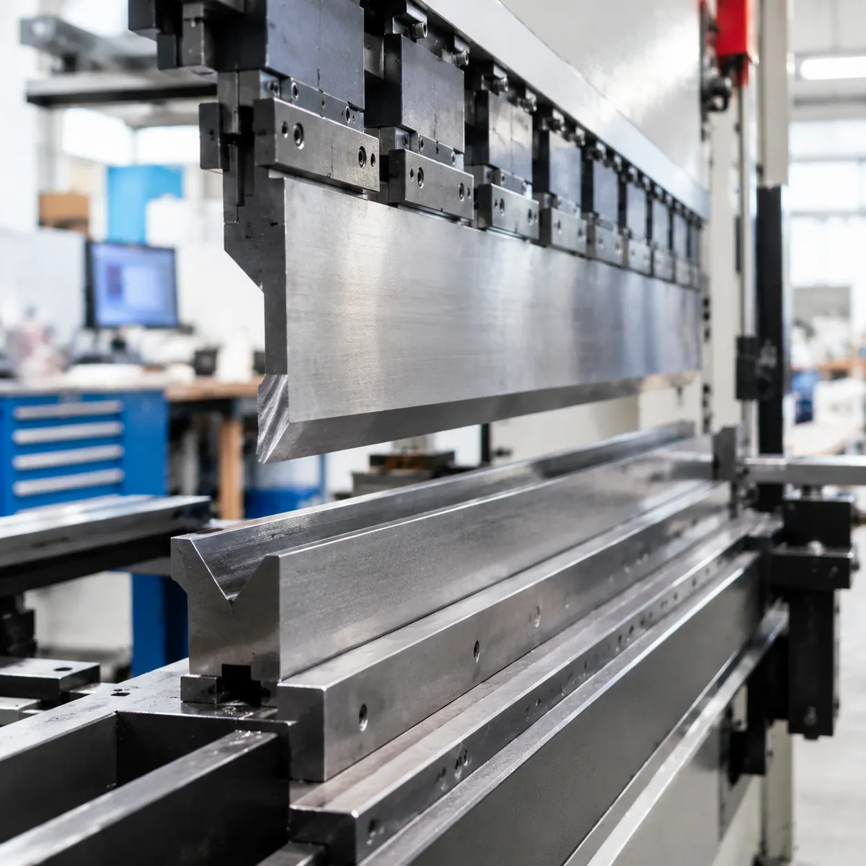
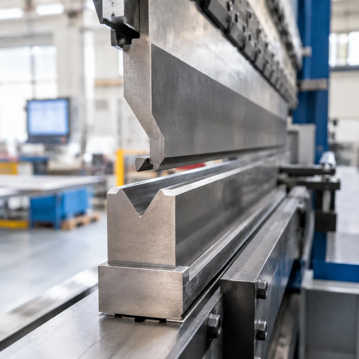
A press brake bottom die, also referred to as lower tooling or a V-die, is the stationary tooling mounted on the lower bed or die holder of a press brake. While the upper punch applies directional bending force, the bottom die supports the sheet metal and dictates the final geometry, bend radius, and angle.
In our fabrication workflows, high-precision bottom dies ensure uniform angle distribution across the entire bed length, eliminate angular deviation caused by springback, and prevent sheet slipping during cycle engagement.
[ Upper Punch ]
│
▼
──────[ Workpiece ]──────
( / )
( Bottom Die / )
___________/
The Interaction Between Punch, Workpiece, and Bottom Die
Forming sheet metal requires a balanced three-point contact dynamic between the upper punch, the metal blank, and the lower tooling shoulders:
- Initial Positioning: The workpiece rests flat across the dual shoulder radii of the bottom die, aligned precisely against the CNC backgauges.
- Force Application: As the punch tip drives downward, it exerts concentrated tonnage along the bend centerline, forcing the blank into the V-opening.
- Elastic-to-Plastic Transition: The material spans the opening like a beam, transitioning past its yield point to take a permanent set.
- Release and Springback: The punch retracts, releasing tonnage while the formed part maintains the target angle minus material-specific springback.
Air Bending, Bottoming, and Coining Bottom Dies
Choosing how the workpiece settles into the bottom die determines required tonnage, part accuracy, and tooling lifespan.
| Bending Method | Penetration Depth | Tonnage Load | Tooling Angle vs. Part Angle | Key Advantage |
|---|---|---|---|---|
| Air Bending | Partial; sheet touches only the punch tip and die shoulders. | Low (Baseline) | Die angle is sharper than target bend (e.g., 85° die for 90° bend). | Maximum flexibility; multiple angles from a single die set. |
| Bottoming | Full contact; sheet is forced against the V-groove faces. | Medium to High (1.5x–2x Air Bending) | Die angle matches target part angle (e.g., 90° die for 90° bend). | High angle repeatability; reduced springback variations. |
| Coining | Severe penetration; punch tip stamps into the neutral axis. | Extreme (5x–8x Air Bending) | Exact match with punch and die geometry. | Sharpest inside radii; zero springback, but rapid tool wear. |
Anatomy of a Precision Bottom Die
A standard bottom die features engineered critical surfaces that directly impact bend tolerance, surface finish, and machine load:
- V-Opening (V): The top width between the contact shoulders. This directly controls the required bending force and natural inside bend radius.
- V-Groove Angle (α): Standard configurations include 30° and 45° for acute bends, 60° and 85°/88° for air-bend springback compensation, and 90° for bottoming.
- Shoulder Radius (Rₛ): The smooth transition curve at the entrance of the V-groove. Polished, hardened shoulder radii reduce drag friction, eliminate part scratching, and prevent premature tool chipping.
- Die Height (H) and Centerline: The distance from the base to the top shoulder. Precise height consistency allows multi-die staging across the bed without shimming.
- Tang / Base Mount: The bottom alignment profile (European Promecam style, American standard tang, or Wila/Trumpf self-seating grooved bases) that locks into the lower die rail.
Common Types of Press Brake Bottom Dies
Selecting the right lower tooling profile directly impacts part accuracy, changeover speed, and surface finish. We categorize the most common press brake bottom dies by their design, flexibility, and intended shop floor applications.
| Die Type | Best Used For | Key Advantage |
|---|---|---|
| Single V-Die | Dedicated high-precision runs | Maximum rigidity & repeatability |
| Double V-Die | Mixed-thickness job shops | Quick flip between two gauges |
| Multi-V / 4-Way | Heavy plate & structural fab | Multiple large openings in one |
| Adjustable V-Die | Heavy CNC automated bending | Zero-tool-change opening shifts |
| Hemming Die | Safety edges and seams | 2-in-1 acute bend & flattening |
| Urethane / Non-Mark | Stainless, aluminum, painted | Zero witness marks on sheet |
Single V-Dies: Precision Single-Opening Tooling
Single V-dies feature one precision-ground V-groove engineered for dedicated production runs.
- High Rigidity: Solid-body design handles high-tonnage forming with minimal center deflection.
- Tight Repeatability: Ground centerlines ensure consistent angular accuracy across long sheet runs.
- Automation-Friendly: Ideal for auto-clamping systems and robotic press brake cells where tooling geometry remains constant.
Double V-Dies: Reversible Versatility
Double V-dies provide two different V-openings on opposite faces of the tool body.
- Fast Gauge Changes: Flip the tool 180 degrees to switch from thin sheet to medium gauge without removing the die rail.
- Space-Saving: Reduces lower tooling storage requirements in compact shop layouts.
- Cost-Efficient: Delivers two distinct bending profiles within a single precision tool.
Multi-V and 4-Way Die Blocks: Heavy-Duty Plate Fabrication
Multi-V and 4-way die blocks are solid, square-profile tools featuring multiple V-groove widths machined across all four sides.
- Heavy Gauge Capacity: Built specifically for thick plate, high-strength alloys, and heavy structural components.
- Handling Options: Rotated manually using overhead cranes or integrated side-lifting pins.
- Economical Heavy Forming: Eliminates the need for multiple large, single-purpose lower dies.
Adjustable V-Dies: CNC Variable-Opening Tooling
Adjustable V-dies use manual shims, mechanical spacers, or CNC servo-driven sliding jaws to adjust the V-opening width dynamically.
- Continuous Range: Infinitely adjust the V-gap to match exact plate thicknesses and springback characteristics.
- Reduced Downtime: Eliminates physical tool swaps when transitioning from 6 mm to 20 mm plate on the same shift.
- High-Tonnage Ratings: Engineered with heavy-duty base saddles to absorb extreme concentrated forming loads.
Hemming and Flattening Bottom Dies: Two-Stage Seaming
Hemming dies combine a 30-degree acute angle groove with a spring-loaded or hydraulic flattening table to produce crushed seams and tear-drop safety hems. Using specialized 30-degree press brake die tooling for air bending and hemming lets us form the initial acute bend and completely flatten the return edge in a single operator pass.
- Stage 1 (Pre-Bend): The punch drives the sheet into the 30-degree groove to create an acute flange.
- Stage 2 (Flatten): The operator pushes the sheet forward onto the flat anvil surface, compressing the flange completely.
- Common Uses: Cabinet doors, appliance housings, ductwork, and handling edges requiring no burrs.
Urethane and Non-Marking Bottom Dies: Surface Protection
Standard steel shoulders leave friction witness lines on sensitive metals. Outfitting lower tooling setups with custom polyurethane radius tooling pads and urethane V-dies prevents surface galling, die marks, and scratching on mirror-finish stainless steel, aluminum panels, and pre-painted sheet.
- Flexible Elastomer Inserts: Distribute forming force over a broader contact zone instead of concentrated shoulder points.
- Roller-Shoulder Alternatives: Lower dies with hardened spinning rollers eliminate drag friction during the air-bending stroke.
- Zero Secondary Polishing: Keeps finished parts ready for final assembly without secondary grinding or buffing.
Tooling Materials and Surface Hardening Treatments
The lifespan and precision of press brake bottom dies come down to two critical factors: the base alloy steel and the heat treatment process. We select specific tool steels to handle heavy localized tonnage without deforming or cracking along the V-groove.
Premium Tool Steels: 42CrMo, 50CrMo4, and Carbon Alloys
- 42CrMo (AISI 4140): The global benchmark for 42CrMo press brake tooling. It delivers exceptional yield strength, impact toughness, and wear resistance under continuous, high-tonnage production cycles.
- 50CrMo4: A high-tensile alloy common in European-style tooling, offering elevated fatigue resistance and superior depth of hardening.
- T8 / T10 (W108 / Carbon Tool Steels): Economical options suited for light-gauge air bending and low-volume job shop runs. They provide solid edge retention but lower shock resistance compared to chromoly alloys.
Induction Hardening vs. Full-Body Heat Treatment
To withstand continuous friction while protecting the tool body from catastrophic fracturing, lower tooling requires targeted metallurgical engineering:
- Localized Induction / Laser Hardening: We apply high-frequency induction or laser treatment directly to high-friction wear zones—specifically the bottom die shoulder radius and V-groove flanks. This achieves a working surface hardness of HRC 55–60 while keeping the core ductile (HRC 28–32) to absorb heavy shock loads.
- Full-Body Through-Hardening: The entire tool is uniformly hardened to HRC 47–52. While this provides consistent structural integrity across the block, it can be more vulnerable to brittle fractures if pushed past maximum tonnage limits on narrow V-openings. Following standard press brake die maintenance tips ensures these hardened surfaces resist micro-cracking over millions of cycles.
| Steel Grade | Primary Heat Treatment | Shoulder Surface Hardness | Core Hardness | Best Application |
|---|---|---|---|---|
| 42CrMo | CNC Induction Hardened | HRC 56–60 | HRC 28–32 | High-precision air bending & thick plate |
| 50CrMo4 | Deep Laser Hardened | HRC 58–62 | HRC 30–35 | High-cycle automated CNC bending |
| T8A / T10A | Through-Hardened | HRC 48–52 | HRC 48–52 | Standard-duty sheet metal fabrication |
Nitriding and Friction-Resistant Surface Coatings
Friction during sheet intake causes galling, pickup, and shoulder wear, especially when forming stainless steel, galvanized sheet, or aluminum. We apply specialized surface treatments to keep tooling surfaces clean:
- Gas or Plasma Nitriding: Infuses nitrogen into the outer surface layer to create a wear-resistant case (up to HV 900–1000) that eliminates material transfer and galling.
- TiCN & PVD Hard Coatings: Ultra-thin protective barriers that lower the friction coefficient, reducing tonnage drag and preventing surface scratching on pre-painted or polished workpieces.
- Black Oxide / Manganese Phosphating: A reliable chemical conversion coating that prevents rust formation and corrosion during daily shop floor operation and shelf storage.
How to Calculate and Select the Right Bottom Die Opening
The 8x Rule and Material Thickness Ratios
For general sheet metal bending, we rely on the industry-standard 8× rule: the V-opening width should equal 8 times the material thickness (V = 8 × T). This ratio delivers an optimal balance between manageable bending tonnage and a tight inside bend radius for standard mild steel and aluminum.
- Mild Steel & Aluminum (0.5 mm–6 mm): Use an 8 × T opening (V = 8 × T).
- Thin Gauge Sheet (< 1 mm): Scale down to 6 × T to achieve crisp, sharp radii.
- Heavy Plate (> 6 mm): Increase to 10 × T to 12 × T to avoid machine overload and excessive edge stress.
Adjusting V-Opening Ratios for Stainless Steel and High-Tensile Alloys
Tougher alloys resist plastic deformation and require wider openings to prevent tooling damage and material cracking:
- Stainless Steel (304 / 316): Use a 10x to 12x T opening. Stainless work-hardens instantly and demands roughly 50% more tonnage than mild steel.
- High-Strength Steels (Hardox, Domex, Weldox): Use a 10x to 14x T opening to avoid fracture along the bend line. For high-yield plate, running heavy-duty press brake die sets for high-strength steel ensures you stay well within safe load thresholds.
| Material Type | Recommended V-Opening Ratio | Inside Bend Radius (Approx.) | Tonnage Factor |
|---|---|---|---|
| Aluminum (5052-H32) | 6× - 8× T | approx 16% of V | 0.5× (Low) |
| Mild Steel (A36 / S275) | 8× T | approx 16% of V | 1.0× (Baseline) |
| Stainless Steel (304) | 10× - 12× T | approx 20% of V | 1.5× (High) |
| High-Tensile Plate | 12× - 14× T | approx 22% of V | 2.0×+ (Very High) |
Calculating Required Bending Tonnage per Meter
Bending force is inversely proportional to the bottom die width. Widening your V-opening drops the required tonnage significantly:
$Tonnage (Metric Tons/Meter) approx frac{1.42 × Tensile Strength (kg/mm²) × T²}{V}$
- Double the V-opening: Cuts required tonnage by approximately 50%.
- Narrow the V-opening: Spikes the tonnage exponentially, risking premature shoulder wear or catastrophic bottom die fracture.
Inside Bend Radius (IR) and Shoulder Geometry
In air bending, the inside radius ($IR$) is formed naturally over the shoulders of the press brake lower tooling rather than matching the punch tip:
- Mild Steel: IR approx 16% of the V-opening width.
- Stainless Steel: IR approx 20% of the V-opening width.
- Bottom Die Shoulder Radius: Larger shoulder radii reduce friction and eliminate sheet galling, while tight shoulder radii help locate smaller parts but increase localized contact pressure.
Minimum Flange Length Rules
A sheet must bridge both shoulders of the bottom die during the entire bending cycle. If a flange is too short, its edge slips off the shoulder radius and drops straight into the V-groove, ruining the bend angle and edge profile.
- Standard 90-degree Bends: Minimum Flange Length approx 70% of the V-opening (0.7 × V).
- Acute 30-degree Bends: Minimum Flange Length approx 75% - 80% of the V-opening.
When bending thick plate with a large V-opening press brake die, always account for this extended flange requirement in your flat pattern layout before cutting parts on the laser or plasma table.
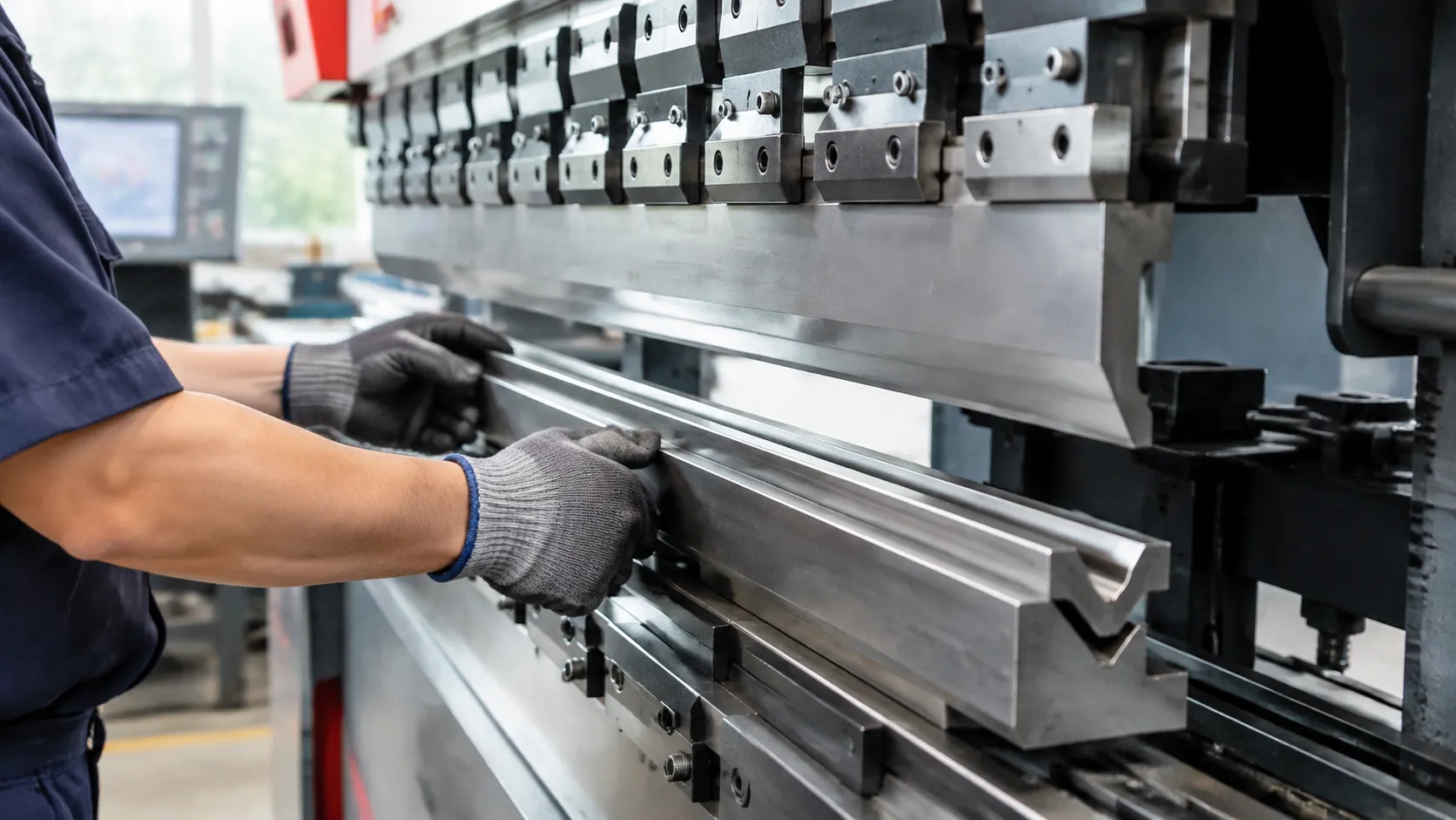
Tooling Standards and Clamping Compatibility for Press Brake Bottom Dies
| Standard | Tang Dimensions / Mount Type | Clamping Mechanism | Best Use Case |
|---|---|---|---|
| European (Promecam) | 12.7 mm × 8.4 mm or 13 mm tang with locating keyway | Set screws / Cam clamps into bottom die rail | Precision job shop work |
| American Traditional | 0.500" × 0.750" (12.7 mm × 19 mm) centered planed tang | Bed set screws / Side-lock bar clamps | Heavy tonnage & structural plate |
| New Standard (Wila / Trumpf) | 13 mm shoulder mount with safety pins or TX alignment grooves | Hydraulic / pneumatic self-seating push buttons | High-speed CNC automated lines |
European / Promecam Style Bottom Dies
European style lower tooling sits on a standard 12.7 mm (0.500") or 13 mm tang, keyed to drop directly into a universal bottom die rail.
- Keyed alignment: Built-in tang slots ensure the V-groove stays centered along the bed without tedious manual shimming.
- Segmented versatility: Available in precision-ground short segments (e.g., 10 mm to 500 mm sections) for bending deep boxes and complex flanges.
- Fast changeovers: Pairs seamlessly with quick-action mechanical or pneumatic clamping bars for minimal downtime between jobs.
American Traditional Standard Bottom Tooling
American style tooling features a centered 0.500" wide by 0.750" tall planed tang, secured directly into the press brake bed slot using set screws. When running legacy equipment or mixed fleets, sourcing a direct press brake die replacement for American and European styles keeps machines running without costly bed remachining.
- Massive tonnage resistance: The solid block design sits directly against the machine bed cap, easily handling severe bottoming and thick plate coining.
- Deep tang seating: Ideal for single V-dies, multi-V die blocks, and 4-way dies on older mechanical and hydraulic brakes.
Wila / Trumpf Style New Standard Bottom Dies
For maximum throughput and tight tolerances, New Standard lower tooling delivers unmatched repeatability. We frequently deploy precision Trumpf style tooling solutions on multi-axis CNC machines to eliminate alignment runs.
- Self-seating and centering: Hydraulic or mechanical clamping seats the die tight against the load-bearing shoulders automatically.
- Safety pins and buttons: Bottom dies click into place horizontally or vertically, preventing drop-in misalignment and speeding up tool staging.
- Tx-axis alignment: Individual mechanical adjustments allow micro-correction of the bending centerline along the full bed length.
Adapters, Die Rails, and Riser Blocks
You do not need to buy all-new bottom tooling if you operate different press brake brands side by side. Cross-platform adapters provide modular compatibility:
- Die rail adapters: Mount European Promecam dies onto standard American slotted beds.
- Riser blocks: Raise bottom die working heights to normalize open height and shut height across different tooling profiles.
- Multi-V holder bases: Secure 4-way and large-opening lower dies directly onto narrow CNC beds while distributing forming tonnage evenly across the bed cap.
Installation, Alignment, and Preventative Maintenance
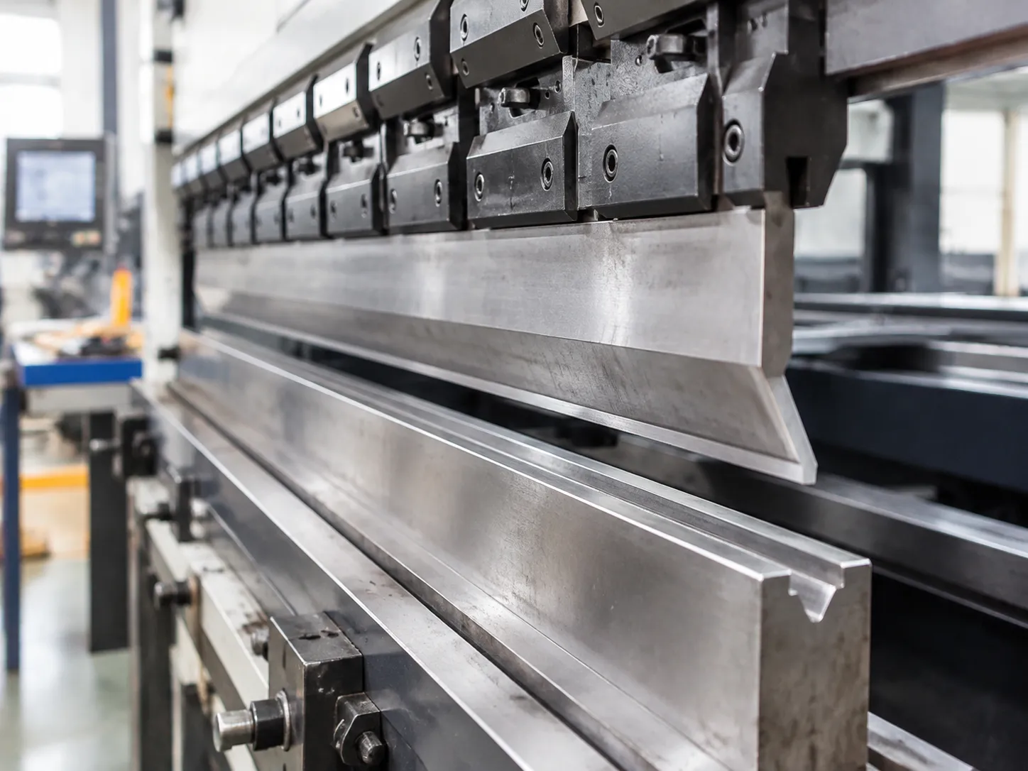
Proper Punch-to-Die Alignment Procedures
Precise centering ensures equal bend angles on both sides of the workpiece and prevents side-thrust damage to your ram and tool holders.
- Clean the Bed and Rails: Wipe away all metal dust, scale, and grit from the lower beam and die rail before seating the tool.
- Loose Seating: Place the lower die into the holder or rail. Leave the mechanical clamping bars slightly loose so the die can float horizontally.
- Low-Pressure Inching: Bring the upper punch down slowly in jog mode until the punch tip nests fully into the center of the V-groove. Apply minimal tonnage (just enough to seat the punch without forming).
- Lock Clamping Uniformly: Tighten the die clamping screws or engage the hydraulic system starting from the center and working outward to both ends.
- Verify Alignment: Check the clearance along the entire bed length using a feeler gauge to ensure zero taper and perfect centerline tracking.
Spotting Shoulder Radius Wear, Chipping, and Deformation
Worn lower tooling creates inconsistent bend angles, sheet slipping, and unsightly surface galling. Inspect your dies regularly for these common failure modes:
| Wear Indicator | Root Cause | Impact on Bending | Recommended Action |
|---|---|---|---|
| Shoulder Radius Flattening | High cycle counts, abrasive scale | Angle variations, increased friction | Regrind or replace the die section |
| Chipping or Micro-Cracks | Over-tonnage, coining hard materials | Part marking, catastrophic fracture risk | Remove from service immediately |
| Centerline Deformation | Off-center loading, uneven clamping | Inconsistent flange dimensions | Re-machine bed/rail or replace die |
| Galling / Material Transfer | Dry bending galvanized or stainless steel | Scratched workpieces, sticky release | Polish shoulders and apply dry film lube |
Safe Tonnage Limits to Prevent Tool Overload
Exceeding the maximum load capacity of a press brake lower die leads to permanent shoulder deformation or sudden, dangerous tool cracking. Always consult a validated European press brake die rating guide for tonnage safety before running high-strength materials or tight V-openings.
- Rule of Thumb: Never apply full machine tonnage across a short tooling section. Load limits are rated in tons per foot or tons per meter.
- Center Point Concentrated Loads: Short dies handle significantly less total tonnage than full-length setups. Calculate local stress to prevent sinking into the lower bed.
Cleaning, Anti-Rust Oiling, and Storage Best Practices
- Post-Shift Wipe Down: Clean all scale, moisture, and debris from the V-groove and shoulder radii using a non-corrosive solvent and a lint-free rag.
- Corrosion Protection: Apply a light coat of industrial anti-rust oil or dry rust-inhibitor spray before putting tooling away.
- Dedicated Tool Racks: Store bottom dies vertically or in compartmentalized, polyurethane-lined drawers. Never stack hardened dies directly on top of each other, as direct steel-on-steel contact chips precision-ground edges.
- Segmented Die Organization: Keep matched, precision-ground die sets grouped and numbered together to maintain uniform height tolerances across long bend lines.
Frequently Asked Questions (FAQ)
What Happens if the Bottom Die V-Opening Is Too Small or Too Large?
Using an incorrect V-die opening size immediately compromises bend quality and shop safety:
Too Small: Spikes required bending tonnage dramatically, risks overloading your press brake lower tooling, creates sharp surface score marks, and can crack high-tensile material. Reviewing a practical press brake die clearance guide ensures your chosen opening balances tonnage and target radius safely.
Too Large: Increases the inside bend radius, causes inconsistent angles due to uncompensated springback, and prevents short flanges from seating properly across the shoulders.
How Do I Calculate the Minimum Flange Length for a Specific Bottom Die?
As a proven rule of thumb for standard 90-degree air bending, the minimum flange length must span safely across the die shoulders before forming begins:
Formula: Minimum Flange = V-Opening × 0.7 (or roughly 70% to 75% of the die width).
Example: With a 16 mm V-die, your finished part needs a minimum flange of approximately 11.2 mm to 12 mm to avoid dropping into the groove during the stroke.
Can I Use the Same Bottom Die for Mild Steel, Stainless, and Aluminum?
Yes, we frequently use the same precision ground bottom die across different alloys, but you must account for distinct material behaviors:
Stainless Steel: Requires an opening 20% to 30% wider or lower angle dies (e.g., 85° or 80°) to handle higher tonnage and aggressive springback.
Aluminum: Demands larger shoulder radii or urethane tape to prevent surface galling. Refer to our press brake die selection for aluminum guide for dedicated alloy-forming setups.
Mild Steel: Follows standard 8x material thickness sizing without special compensation.
What Causes Premature Wear on Bottom Die Shoulders?
Shoulder degradation on your press brake lower die typically stems from four shop-floor mistakes:
Forming Heavy Mill Scale: Bending uncleaned hot-rolled plate grinds abrasive oxides directly into the shoulder radius.
Exceeding Tooling Tonnage: Over-tonnage from undersized V-openings crushes the induction-hardened surface layer.
Lack of Lubrication: Dry, unlubricated contact zones increase friction, causing localized galling and metal pick-up.
Improper Material Alignment: Bending off-center side-loads the die shoulders, creating uneven diagonal grooving.
How Do Self-Centering Bottom Die Holders Improve Setup Times?
A self-centering bottom die holder eliminates manual alignment steps entirely:
Automatic Line-Up: Hydraulic or pneumatic clamping seats the die tang flush against the machine bed reference point instantly.
Zero Dial-Indicator Setup: Operators drop segmented lower tooling straight into the rail without manual shimming or slow eyeball test bends.
Repeatable Accuracy: Maintains rigid centerline accuracy across multiple tool stations, reducing job changeover downtime from minutes to seconds.