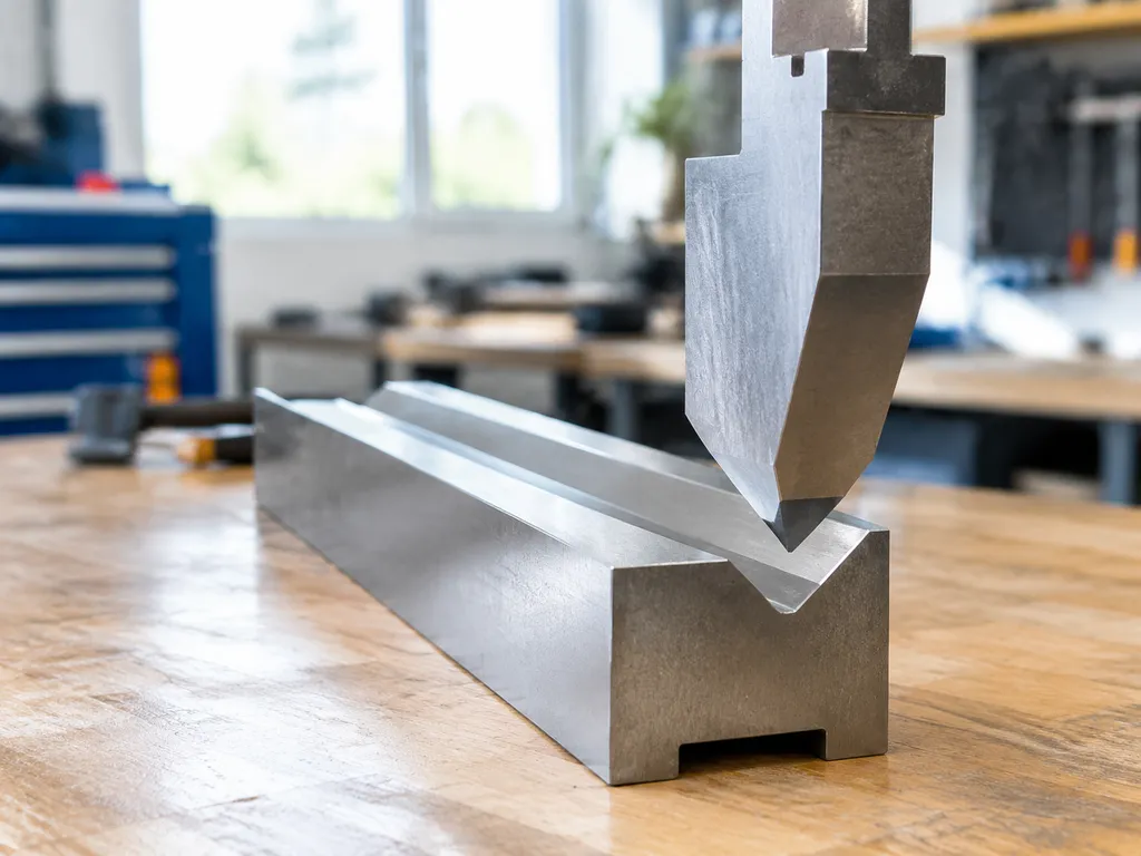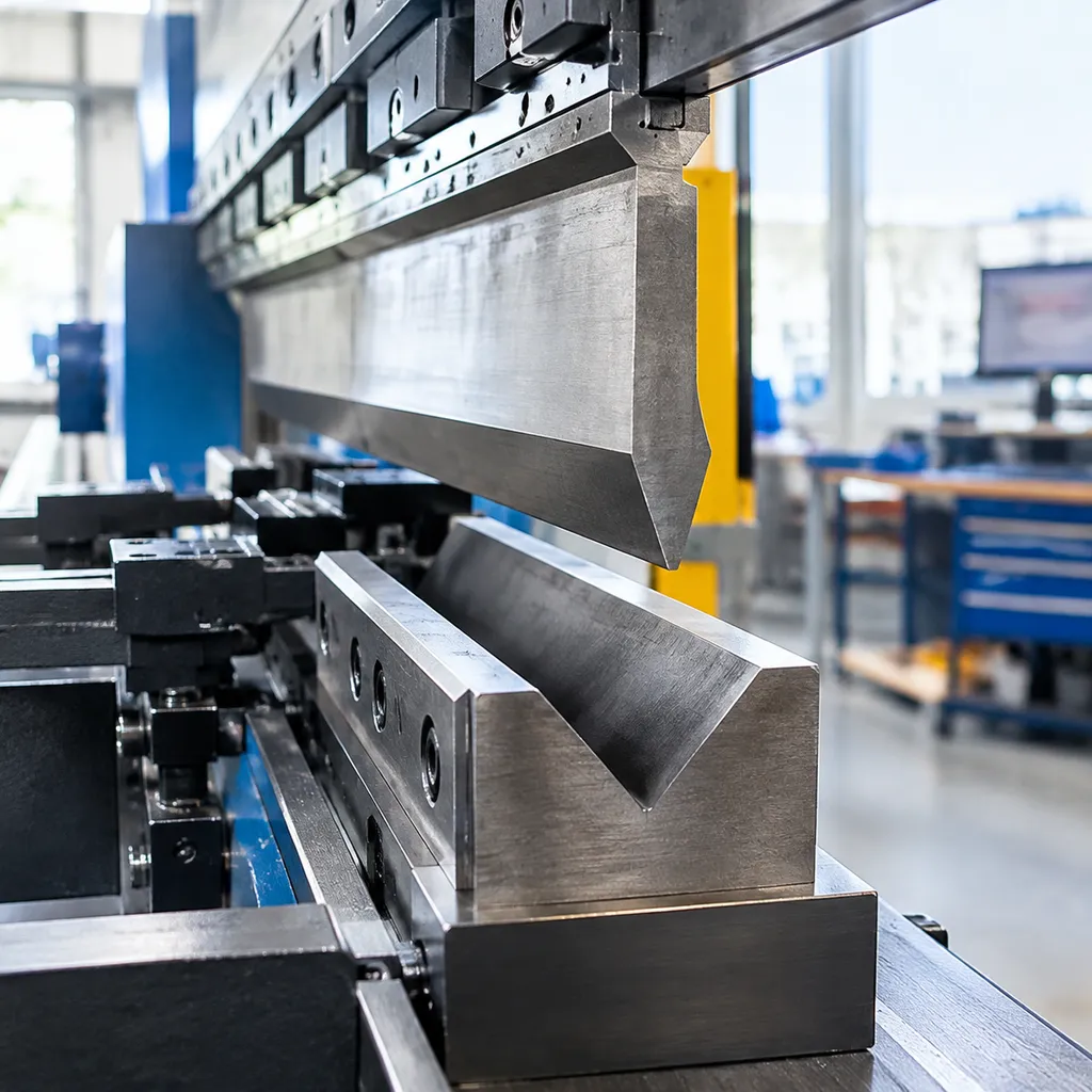

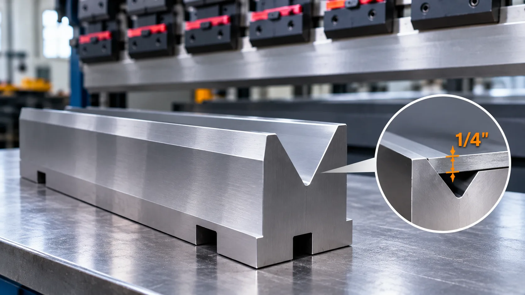
The Standard 8× Rule for 1/4" Plate
When setting up a press brake for 1/4" plate (0.250 in / 6.35 mm), selecting the right bottom die opening dictates your tonnage, inside bend radius, and part geometry. In our production runs, the foundational baseline is the 8× rule:
V-Opening = 8 × Material Thickness (T)
Using an opening proportional to 8 times the material thickness strikes the optimal balance between forming pressure and clean part cosmetics. Deviating without a calculation risks exceeding your tooling load limit or tearing the tensile surface of the plate.
Why the 2.0-Inch V-Die is the Industry Standard
Applying the 8× rule yields an exact target:
8 × 0.250 in = 2.000 in (50.8 mm)
The 2.0-inch V-die opening serves as the universal standard bottom die for 1/4" plate for several physical reasons:
- Tonnage Efficiency: Keeps bending load within standard hydraulic capacities, averaging 15.5 to 16.0 tons/ft (460 to 475 kN/m) for structural mild steel.
- Natural Radius Formation: In air bending, the inside bend radius (Rᵢ) forms naturally as roughly 16% of the die opening (Rᵢ ≈ 0.16 × V). A 2.0" die naturally yields an inside radius of approximately 0.320 in (8.1 mm), preventing the metal core from shearing.
- Shoulder Contact Stability: The shoulder radius on a standard 2.0" die supports the plate across its yield transition, stopping premature draw-in and edge distortion.
Quick Reference: Air Bending 1/4" A36 Steel
For rapid setup on the shop floor, reference these baseline parameters when air forming 1/4" A36 mild steel on a standard 2.0" die:
| Parameter | Imperial Specification | Metric Equivalent |
|---|---|---|
| Material Thickness (T) | 0.250 in | 6.35 mm |
| Die Opening (V) | 2.000 in | 50.8 mm |
| Die Shoulder Radius (Rₛ) | 0.236 in | 6.0 mm |
| Expected Inside Radius (Rᵢ) | ~0.312–0.330 in | 7.9–8.4 mm |
| Minimum Flange Height (b) | 1.400 in | 35.5 mm |
| Forming Load (A36) | 15.8 tons/ft | 468 kN/m |
Understanding V-Opening Variations: 6×, 10×, and 12×
While the 8× standard handles most daily fabrication, specific part designs and material properties require moving outside the default:
- 6× Die Opening (1.50 in / 38.1 mm): Used only when a drawing calls for a short minimum flange length (~1.05 in / 26.7 mm). Caution: Required tonnage increases by roughly 33% to over 21 tons/ft (620 kN/m), drastically accelerating tool wear and increasing the risk of plate fracture.
- 10× Die Opening (2.50 in / 63.5 mm): Selected to reduce tonnage down to roughly 12.5 tons/ft (370 kN/m). This configuration protects lighter-tonnage press brakes and yields an inside radius of approximately 0.400 in (10.2 mm).
- 12× Die Opening (3.00 in / 76.2 mm): The primary choice for harder alloys, materials with higher yield strengths, or parts with bend lines parallel to the rolling grain. Tonnage drops to around 10.5 tons/ft (310 kN/m), preventing cracking along the outer tensile radius at the expense of a larger flange requirement (~2.10 in / 53.3 mm).
Bottom Die Selection Mechanics
Forming heavy plate demands absolute control over your tooling setup. When selecting a standard bottom die for 1 4 sheet metal (6.35 mm), your choice dictates machine load, minimum flange limits, and angular repeatability. We always establish our setup parameters using our press brake die selection guide for precise bending to maintain consistent quality across heavy structural runs.
PUNCH
│
▼
═════════════ <-- 1/4" (6.35 mm) Plate
/ \
/ V-DIE \ <-- Shoulder Contact Only (Air Bending)
/ Angle \
Air Bending vs. Bottoming for 1/4" Plate
Bottoming or coining 1/4" plate is an unnecessary risk that quickly destroys tooling and beds. Air bending is the universal production standard for plate fabrication.
| Parameter | Air Bending | Bottoming / Coining |
|---|---|---|
| Tool Contact | 3 points (Punch tip + 2 die shoulders) | Full surface contact in the V-opening |
| Tonnage Demand | Baseline (~16 tons/ft / 525 kN/m on a 2.0" die) | 4× to 6× baseline (64–100+ tons/ft / 2,100–3,280 kN/m) |
| Angular Flexibility | Any angle achievable with depth control | Locked to the mechanical profile of the die |
| Tooling Wear | Minimal shoulder friction | Severe galling, shoulder deformation, bed deflection |
| Machine Safety | Safely within rated machine capacities | High risk of exceeding center-bed load limits |
Bottoming 1/4" plate requires immense tonnage that regularly fractures standard hardened tooling. Air bending allows us to hit tight tolerances while working well within safe operating limits.
The Floating Radius Principle
In air bending, the punch nose profile does not produce the inside bend radius (Rᵢ) under normal conditions. Instead, the radius forms naturally in the space between the die shoulders—a phenomenon known as the floating radius.
The 16% Rule (A36 Mild Steel): The natural inside bend radius forms at roughly 15% to 17% of the press brake V-die opening (V).
Mathematical Calculation:
Rᵢ = V × 0.16
- Application on 2.0-inch (50.8 mm) V-Die:
Rᵢ = 2.0 in × 0.16 = 0.32 in (8.13 mm)
If you switch from a 2.0" (50.8 mm) die to a 2.5" (63.5 mm) die, your inside radius increases from 0.32" (8.13 mm) to 0.40" (10.16 mm), regardless of the punch tip radius. The punch tip only controls the radius if it is ground larger than the natural floating value.
Selecting Die Angles for Springback
Every structural plate exhibits elastic recovery upon stroke return. Standard 1/4" A36 mild steel typically rebounds by 1° to 2°, while structural grades (such as ASTM A572 or high-strength alloys) regularly show 3° to 5° of springback.
To achieve a true finished 90° bend profile without bottoming out the sheet metal, the tool profile must provide angular clearance:
- 90° Dies: Unsuitable for air bending 1/4" plate. Attempting to compensate for springback in a 90° die drives the plate against the die walls, transforming the stroke into bottoming and spiking the tonnage.
- 85° to 88° Acute Dies: The industry standard. These dies allow the punch to drive the plate to 88° or 89°, giving the part room to recover naturally to a clean 90° upon release.
Consult our press brake die angles guide for springback selection to match the ideal die relief angle with your specific material yield strength and plate thickness.
Adjusting Die Openings by Material Grade
Relying strictly on the standard 8× rule for every job will quickly damage tools or ruin parts. While a 2.0-inch (50.8 mm) opening serves as the standard bottom die for 1/4 sheet metal in basic mild steel, shifting material grades changes the physics completely. Yield strength, elongation limits, and work-hardening rates dictate whether we open the die up or drop it down to maintain clean bend lines without exceeding our machine limits.
1/4″ (6.35 mm) Plate Die Selection by Material Grade
| Material Grade | Recommended V | Die Ratio | Approx. Tonnage | Est. Inside Radius |
|---|---|---|---|---|
| A36 Mild Steel | 2.00 in (50.8 mm) | 8× | 15.5 t/ft (455 kN) | 0.32 in (8.1 mm) |
| 304/316 Stainless | 2.50 in (63.5 mm) | 10× | 19.0 t/ft (558 kN) | 0.40 in (10.2 mm) |
| 5052-H32 Aluminum | 1.75 in (44.5 mm) | 7× | 7.5 t/ft (220 kN) | 0.28 in (7.1 mm) |
| 6061-T6 Aluminum | 2.50 in (63.5 mm) | 10×–12× | 11.0 t/ft (323 kN) | 0.42 in (10.7 mm) |
| AR400 / AR500 | 3.00 in (76.2 mm) | 12× | 38.0 t/ft (1115 kN) | 0.55 in (14.0 mm) |
Guidelines for A36 Mild Steel
For standard 1/4-inch (6.35 mm) A36 structural plate, the 2.0-inch (50.8 mm) V-die remains our everyday baseline.
- Yield Profile: Typical yield strength sits between 36,000 and 42,000 PSI (250–290 MPa).
- Load Profile: Requires approximately 15.5 tons per foot (455 kN/m).
- Formed Radius: Produces a natural inside bend radius (Ri) around 0.32 inches (8.1 mm) via air bending.
- Shop Practice: If the plate has heavy mill scale, wipe the die shoulders frequently to prevent scale from embedding into the tooling shoulders and marring subsequent parts.
Bending Stainless Steel (304/316)
Austenitic stainless steels work-harden aggressively the moment the punch contacts the plate. Bending 1/4-inch 304 or 316 on a standard 2.0-inch die spikes tonnage by roughly 50%, putting unnecessary stress on press brake side frames and tooling shoulders.
We bump the press brake V-die opening up to 2.50 inches (63.5 mm)—a 10× ratio:
Reduces the required forming tonnage from over 23 tons/ft down to a manageable 19 tons per foot (558 kN/m).
Accommodates a larger natural inside radius (approx. 0.40 inches / 10.2 mm) without orange-peeling or tearing the outer bend radius.
Minimizes galling along the die shoulders. For high-volume production, we run dedicated dies engineered for heavy stainless steel processing to prevent iron contamination and shoulder wear.
Aluminum Alloys (5052 vs. 6061)
Selecting a die for 1/4-inch aluminum depends heavily on the alloy temper:
- 5052-H32: Highly ductile with great formability. We routinely drop the V-die opening to 1.75 inches or 2.0 inches (44.5 to 50.8 mm) to hit crisp, tight flange dimensions. Cracking is rarely an issue, and forming demands only about 7.5 tons per foot (220 kN/m).
- 6061-T6: Extremely brittle in plate thicknesses. Forcing 1/4-inch 6061-T6 into a standard 2.0-inch die will fracture the outer fibers along the bend line. We open the die to 2.5 inches to 3.0 inches (63.5 to 76.2 mm) and use a punch with a matching broad nose radius to prevent catastrophic part splitting.
High-Strength and AR Plate (AR400/500)
Forming abrasion-resistant and high-yield plate (yield strengths from 100,000 to 180,000 PSI / 690 to 1240 MPa) demands an entirely different approach to bottom die selection.
Standard 8× dies are out of the question here; using them will break your tooling or stall the ram.
- Die Width: Open the die to 10× to 12× material thickness—specifically 2.50 to 3.00 inches (63.5 to 76.2 mm) as an absolute minimum, with 3.5 inches (88.9 mm) preferred for AR500.
- Tonnage Warning: Tonnage surges rapidly, frequently hitting 35 to 45 tons per foot (1020–1320 kN/m) even with an expanded opening.
- Tooling Integrity: Extreme point loading can crush standard induction-hardened tool shoulders. We run premium-grade press brake die steel treated specifically to handle deep-penetration wear and shock loading during high-strength plate bending.
- Bend Orientation: Always bend transverse (across) the rolling grain to keep hard plate from cracking wide open under load.
Geometric Constraints in Heavy Plate Bending
Bending 1/4" (6.35 mm) plate requires strict attention to physical geometry. When we step up to heavy plate, standard clearance rules tighten up fast. You cannot simply force a short lip over a standard bottom die for 1/4 sheet metal and expect a clean bend. The sheet must bridge the V-opening securely across both die shoulders throughout the entire stroke. If the blank edge slips off a shoulder early, the sheet drops unevenly into the V-cavity, ruining the part and posing a serious safety hazard to your backgauge fingers and tooling.
Calculating Minimum Flange Length
To form an accurate 90-degree bend without the part falling into the die pocket, the blank must maintain continuous contact with both die shoulders until the punch initiates plastic deformation.
For air bending on a standard 2.0-inch (50.8 mm) V-die opening, we calculate the minimum external flange length using a shop-proven baseline:
- General Rule of Thumb: Minimum Flange = 70% to 75% of V-Die Opening
- Standard 2.0" (50.8 mm) V-die: Minimum Flange = 1.40" to 1.50" (35.5 mm to 38.1 mm)
- Tight 1.5" (38.1 mm) V-die: Minimum Flange = 1.05" to 1.12" (26.6 mm to 28.5 mm)
- Wider 2.5" (63.5 mm) V-die: Minimum Flange = 1.75" to 1.88" (44.5 mm to 47.7 mm)
For precision work, calculate your exact minimum outside flange (b_{min}) with this formula:
bₘᵢₙ = (V / 2) + Rₛ + 0.5 × T
Where:
V: V-die opening width\
Rₛ: Die shoulder radius\
T: Material thickness (0.25″ / 6.35 mm)
If your print specifies a flange shorter than 1.40" on a 1/4" plate, you cannot run it safely across a standard 2.0" opening. You must either reduce the die opening to a 1.5" V-die (accepting the spike in required tonnage) or source specialized specialty tooling with offset insert supports. Evaluating part geometry alongside a dedicated press brake die clearance guide keeps you from crashing tools when handling these tight flange returns.
The Impact of Die Shoulder Radius (Rₛ)
The die shoulder radius (Rₛ) forms the transition zone where the 1/4" plate slides into the V-opening under intense pressure. On heavy plate, this profile variable dictates your surface quality, tool wear, and net tonnage demand.
| Shoulder Radius Size | Value for 2.0" V-Die | Operational Impact on 1/4" Plate | Recommended Use |
|---|---|---|---|
| Sharp / Under-Radiused | < 0.125"\ (3.2 mm) | High friction, severe surface gouging, premature tool chipping, elevates tonnage by 10–15%. | Avoid on 1/4" plate. |
| Standard Radius | 0.157"\ to\ 0.236"\ (4.0\ to\ 6.0 mm) | Smooth blank slide, minimal drag marks, standard baseline tonnage, uniform bend line. | Standard A36 mild steel bending. |
| Generous / Hardened Radius | 0.315"\ (8.0 mm)+ | Drastically cuts surface marring, lowers friction, requires longer minimum flange. | Polished stainless, aluminum, AR plate. |
A sharp shoulder radius creates severe drag lines and cold-works the outside radius of the plate before the bend even finishes. For standard 1/4" plate air bending, we always specify a minimum shoulder radius of 0.187" to 0.250" (4.76 mm to 6.35 mm). This smooth entry radius lets the heavy plate draw into the pocket cleanly without digging into the tool steel.
Tonnage Analysis and Press Brake Protection
Bending quarter-inch plate demands respect for machine capacity and tooling load limits. We calculate forming tonnage before every setup because running an undersized opening on heavy plate can split a die shoulder, permanently cup the ram, or crack side frames. Using the correct standard bottom die for 1 4 sheet metal ensures we stay well within safe working loads while maintaining tight angular tolerances.
The Standard Tonnage Formula
To estimate air bending force for standard A36 mild steel (tensile strength around 60,000 PSI / 414 MPa), we rely on the proven empirical tonnage formula:
- Tonnage (US tons per foot) = (575 × t²) / V
- Tonnage (Metric kN per meter) = (1.42 × UTS × t²) / V
Where:
t = Material thickness (0.250 in / 6.35 mm)
V = Bottom die V-opening width (inches or mm)
UTS = Ultimate tensile strength in kg/mm² (for metric calculations)
When shifting to materials like 304 stainless steel, multiply the final tonnage by a factor of 1.4 to 1.6. For high-strength grades like Hardox or Domex, that multiplier easily exceeds 2.0. Consult our comprehensive press brake V-die chart and tonnage guide to verify tonnage factors across non-standard alloy groups.
Tonnage Comparison Table (1.5" to 3.0" V-Dies)
The width of the V-opening dictates the required forming force. Narrowing the die opening spikes the load exponentially, while widening it drops the required tonnage at the expense of an increased inside radius.
The values below apply to air bending 0.250-inch (6.35 mm) A36 mild steel plate:
| V-Die Opening Width | Die-to-Thickness Ratio | Tonnage Required (US Tons/Ft) | Tonnage Required (kN/m) | Resulting Inside Radius (Ri) |
|---|---|---|---|---|
| 1.500 in (38.1 mm) | 6× | 24.0 tons/ft | 785 kN/m | 0.240 in (6.1 mm) |
| 2.000 in (50.8 mm) | 8× (Standard) | 18.0 tons/ft | 588 kN/m | 0.320 in (8.1 mm) |
| 2.500 in (63.5 mm) | 10× | 14.4 tons/ft | 470 kN/m | 0.400 in (10.2 mm) |
| 3.000 in (76.2 mm) | 12× | 12.0 tons/ft | 392 kN/m | 0.480 in (12.2 mm) |
Opting for the 2.0-inch (50.8 mm) bottom die provides the best balance: it requires an accessible 18 tons per foot (588 kN/m), preserves standard structural radii, and avoids overloading intermediate tooling tangs.
Preventing Tooling Overload
Every bottom die has a maximum centerline load rating that must never be exceeded. Overload failures rarely happen across an entire 10-foot bed; they occur as localized point-load fractures when operators bend short, thick parts on narrow dies.
Key shop practices to protect your press brake and tooling:
- Check Shoulder Load Capacities: Hardened ground tooling has rated load limits marked directly on the tool face. Cross-reference your calculated part load against our European press brake die rating guide for tonnage safety before cycling the ram.
- Avoid High Concentrated Loads: Bending a 2-inch wide tab of 1/4" plate in a narrow die concentrates tens of tons across a tiny contact footprint, creating severe shoulder brinelling.
- Compensate for Bed Deflection: High tonnage across long spans flexes the center of the bed and ram. Match your machine's dynamic crowning settings to the tonnage profile of the selected V-die to avoid boat-shaped parts with open center angles.
Bottom Die Configurations for Heavy Fabrication
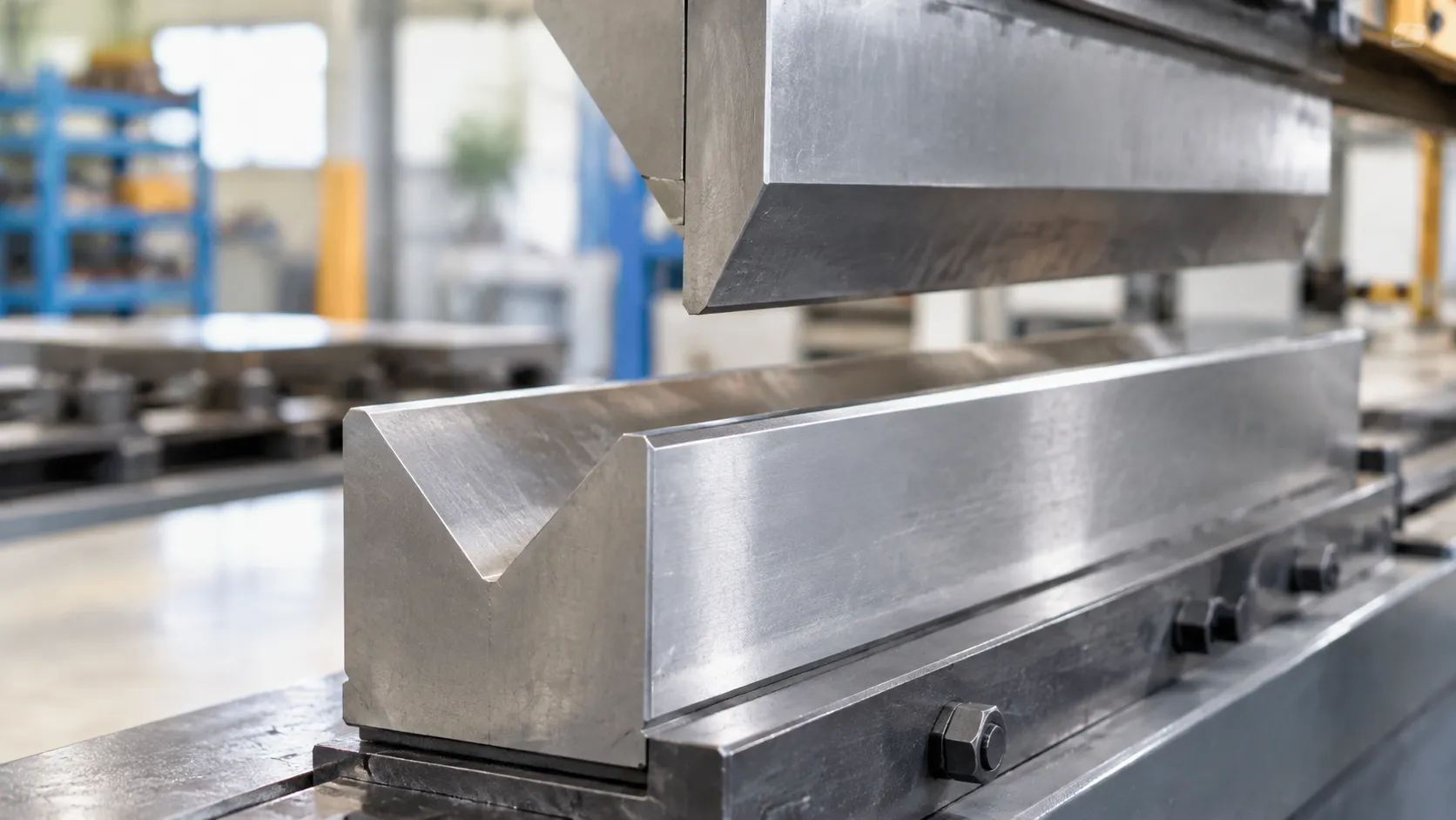
Multi-V Dies vs. Single-V Blocks
When cycling through production runs of 1/4" plate, tool rigidity and bed alignment dictate your part accuracy.
- Single-V Blocks: These are our workhorses for heavy plate sheet metal fabrication. A dedicated single-V block provides a solid, direct load path straight down into the press brake bed. Because there are no opposing pockets or offset relief cuts, single-V dies resist spread under high tonnages—upwards of 15 to 20 tons/ft (490 to 650 kN/m). They seat solidly against mechanical crowning tables, eliminating centerline deflection.
- Multi-V and 2-V Blocks: While multi-V dies save storage space, rotating an 80-pound-per-foot 4-way block to switch from a 1.5" to a 2.0" opening creates safety hazards and slow setups. For high-mix runs, hardened 2V press brake dies strike the right balance between rapid flipping and the mass needed to withstand structural steel bending forces.
| Die Configuration | Typical V-Opening Range | Weight & Handling | Best Application |
|---|---|---|---|
| Solid Single-V | Fixed: 2.0" (50.8 mm) or 2.5" (63.5 mm) | Moderate; requires crane for long sections | High-tonnage A36 runs, tight production tolerances |
| Multi-V (4-Way) | Variable pockets: 0.5" to 2.5" | Heavy; high setup and rotation time | Low-volume maintenance shops, mixed gauges |
| 2-V Reversible | Dual: e.g., 1.5" & 2.0" (38.1 & 50.8 mm) | Balanced; fast mechanical clamping | Production batch transitions between 3/16" and 1/4" plate |
Variable and Adjustable V-Dies
Crane-handling heavy solid dies every time plate yield strengths drift eats away at spindle time. We resolve this by running CNC-controlled or shim-driven adjustable press brake dies for our heavy-duty lines.
- Continuous Opening Control: With motorized or manual adjustability, we shift our press brake V-die opening from 1.5" (38 mm) up to 8.0" (200 mm) in seconds without removing the base tool from the holder.
- Targeted Springback Management: If an off-spec batch of 1/4" plate demands an extra 10% die clearance to prevent tonnage spikes, we fine-tune the shoulder spacing directly at the machine control, preserving the exact target inside radius.
Using Roller-Bearing Insert Dies
Dragging 1/4" structural plate over static tool shoulders generates massive frictional resistance, driving up tonnage demands and scarring the workpiece.
To eliminate galling and lower our machine load, we integrate press brake dies with rollers. Hardened, replaceable roller-bearing inserts rotate on entry as the punch drives the material down:
- Tonnage Drop: Friction loss drops substantially, slashing the required bending tonnage by 10% to 25% compared to conventional ground shoulders.
- Flange Conservation: The rolling contact reduces the minimum flange requirement, letting you bend shorter legs without the plate slipping off the shoulder.
- Surface Integrity: Tooling pick-up on stainless steel or aluminum grades is eliminated, preventing secondary grinding and preserving cosmetic finishes on heavy-gauge projects.
Troubleshooting 1/4" Plate Bending Defects
Forming heavy plate reveals every flaw in your tooling setup immediately. When we bend 1/4" (6.35 mm) plate on a press brake, parts that crack, twist out of tolerance, or leave the machine with heavy galling point to a direct clash between material limits and tooling geometry.
Solving Cracking Along the Bend Line
Outer fiber cracking along the bend line usually comes down to grain orientation and an overly aggressive inside bend radius. When using a standard bottom die for 1 4 sheet metal—typically a 2.0" (50.8 mm) V-opening—the natural floating inside radius lands at roughly 0.30" to 0.32" (7.6 mm to 8.1 mm). If your punch nose is too sharp, or if you force the bend along the longitudinal grain, the tensile stress exceeds the material's fracture limit.
- Orient Across the Grain: Always lay out flat patterns so the bend axis runs transverse (90°) or diagonal (45°) to the rolling direction of the plate.
- Increase Punch Tip Radius: Stop using a 0.030" or 0.060" (0.8 mm to 1.5 mm) punch nose on heavy plate. Step up to at least a 0.125" to 0.250" (3.18 mm to 6.35 mm) radius to distribute tensile strain across the outer boundary.
- Widen the Press Brake V-Die Opening: For high-strength or less ductile grades, expand your V-width from the 8× rule (2.0" / 50.8 mm) up to a 10× (2.5" / 63.5 mm) or 12× (3.0" / 76.2 mm) opening. This naturally increases the floating radius and drops localized strain.
Managing Angular Inconsistency
If your 1/4" (6.35 mm) parts come out at 90° on the ends but 93° in the center, you are dealing with machine bed deflection. Generating 15 to 20 tons per foot (440 to 585 kN/m) pushes the ram up and the bed down, resulting in the classic "canoe effect."
- Recalibrate CNC Crowning: Ensure your mechanical or hydraulic crowning system matches the exact tonnage curve of your 1 4 inch sheet metal bending profile.
- Manual Bed Compensation: On brakes without dynamic crowning, you must know how to properly shim an air bending press brake die to offset mechanical deflection across the center of your die holder.
- Inspect Mill Scale and Thickness Variation: Plate thickness can vary by ±0.010" to 0.015" (0.25 mm to 0.38 mm) across a single sheet. In air bending, this variance alters depth penetration and causes angular drift; compensate by grouping blanks by measured thickness before forming.
Addressing Surface Marring
The high tonnage required to bend heavy plate forces the metal to drag hard across the shoulder edges of your bottom die. This contact causes severe scoring, mill scale gouging, and iron transfer on aluminum or stainless parts.
| Cause of Marring | Practical Correction |
|---|---|
| Sharp Die Shoulders | Run dies with a polished shoulder radius ($R_s$) of at least 0.236" to 0.315" (6 mm to 8 mm) to minimize point-contact friction. |
| Mill Scale Embedding | Wheel-abrade or acid-pickle hot-rolled A36 parts prior to bending to prevent pulverized scale from galling the die throat. |
| Tooling Transfer on Sensitive Alloys | Use heavy-duty urethane die-cover tape (0.020" to 0.030" / 0.5 mm to 0.8 mm thick) or install specialized roller-bearing insert dies to switch sliding friction into rolling contact. |
CAMT Precision Tooling Solutions
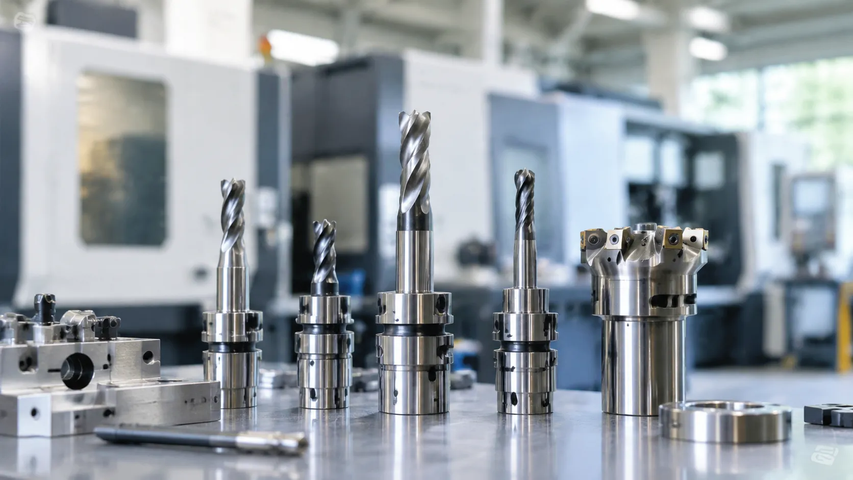
High-Precision Ground V-Dies
A reliable bend starts with a stable die base and an accurate groove. Standard planed dies often exhibit dimensional variations that trigger angular inconsistency along the length of heavy plate. We manufacture our tooling through precision CNC deep-grinding after induction heat treatment to guarantee uniform performance across the entire bed.
- Tolerances: Critical working surfaces, including shoulder radii ($Rs$) and V-openings, are held within ±0.0008" (±0.02 mm).
- Material & Hardness: Machined from premium 42CrMo (AISI 4140) alloy steel, through-hardened to 28–32 HRC, with high-frequency hardened working shoulders reaching 56–60 HRC to a depth of $0.12"$ (3.0 mm).
- Standard Bottom Die Openings: For shops standardizing on quarter-inch plate, our press brake bottom die 3-5 precision tooling features optimized shoulder radii that reduce friction, limit dragging marks, and lower the bending force required on heavy structural frames.
Custom V-Die Profiles
Off-the-shelf dies do not always fit high-yield-strength components, narrow flanges, or return bends with tight clearance limits. For operations that step outside the traditional 8× rule or run into clearance issues, we design and produce specialized profiles matched to your machine's clamping style:
- Custom Relief Angles: 80°, 85°, or acute angles designed specifically to handle large springback in high-strength materials like AR400 or Domex.
- Narrow Shoulder Geometries: Modified shoulders to achieve shorter minimum flange lengths on 1/4" sheet metal without collapsing the sheet edge into the die cavity.
- Segmented and Solid Configurations: Available in precision-matched segmented lengths for easy manual handling or full-length solid blocks up to 20 feet (6 meters) for seamless heavy bending.
- Integrated Tooling Packages: Pair custom dies directly with matched press brake punch and die high-precision tooling systems to ensure tool centerline alignment and eliminate side-load deflection during forming.
Frequently Asked Questions: Standard Bottom Die for 1/4" Sheet Metal
When setting up a standard bottom die for 1/4 sheet metal (6.35 mm), practical floor realities often challenge textbook formulas. Here are direct answers to the most common tooling and setup questions we encounter on the shop floor.
Can I use a 1.5" (38.1 mm) V-die for 1/4" steel?
Yes, but only if your machine tonnage and tooling limits allow it. A 1.5" (38.1 mm) opening represents a 6× material thickness ratio (6 × 0.25"). While a 2.0" (50.8 mm) V-die remains the shop baseline, dropping to 1.5" is common when forming shorter flanges.
- Tonnage penalty: Forming A36 mild steel over a 1.5" die requires roughly 20 to 22 tons per linear foot (600 to 650 kN/m), compared to just 15.3 tons/ft (450 kN/m) over a 2.0" die.
- Tonnage limit check: Ensure your press brake bed and the specific bottom die shoulder ratings can withstand the concentrated load without permanent deformation.
| Die Width (V) | Die-to-Thickness Ratio | Required Tonnage (A36) | Resulting Inside Radius (Ri) | Min. Flange Length |
|---|---|---|---|---|
| 1.50" (38.1 mm) | 6× | ~21 tons/ft (620 kN/m) | ~0.24" (6.1 mm) | ~1.05" (26.7 mm) |
| 2.00" (50.8 mm) | 8× (Standard) | ~15.3 tons/ft (450 kN/m) | ~0.32" (8.1 mm) | ~1.40" (35.6 mm) |
| 2.50" (63.5 mm) | 10× | ~12.2 tons/ft (360 kN/m) | ~0.40" (10.2 mm) | ~1.75" (44.5 mm) |
What is the ideal punch tip radius?
For air bending 1/4" (6.35 mm) carbon plate, the ideal punch nose radius is 0.125" to 0.250" (3.18 mm to 6.35 mm).
- Avoid sharp punches: Using a punch tip radius smaller than 0.080" (2.0 mm) induces a sharp bend condition, creasing the inner bend line and driving up cracking risks.
- The 1:1 rule: Matching punch radius to material thickness (0.250" / 6.35 mm) produces predictable inside radii, prevents material coining, and protects both the punch tip and our CNC press brake die for precise metal bending from localized stress fractures.
Does grain direction impact die choice?
Grain direction directly dictates how wide your bottom die must be:
- Bending with the grain (longitudinal): Yields a high risk of cracking along the outside radius. To compensate, increase the bottom die opening from an 8× ratio (2.0" / 50.8 mm) to a 10× or 12× ratio (2.5" to 3.0" / 63.5 to 76.2 mm). This lowers required tonnage and opens up the natural inside bend radius.
- Bending across the grain (transverse): Allows you to use the standard 8× (2.0" / 50.8 mm) V-die with minimal risk of tensile fractures on the outer face.
Gauge vs. plate bending requirements?
Transitioning from gauge sheet metal (10-gauge and thinner) to 1/4" plate requires significant shifts in setup and process control:
- Scale and surface condition: Unlike cold-rolled sheet, hot-rolled 1/4" plate carries mill scale that breaks off in the V-die, requiring regular cleaning to avoid depth inconsistencies.
- Inside bend radius behavior: Gauge material takes the exact profile of the punch nose much earlier. On 1/4" plate, the inside radius floats naturally to roughly 15% to 17% of the bottom V-die opening during air bending, regardless of minor punch variations.
- Shoulder friction: Heavy plate increases dragging resistance over die shoulders. Hardened, generously radiused die shoulders are mandatory to keep the material flowing smoothly into the V-cavity without galling tool steel.