
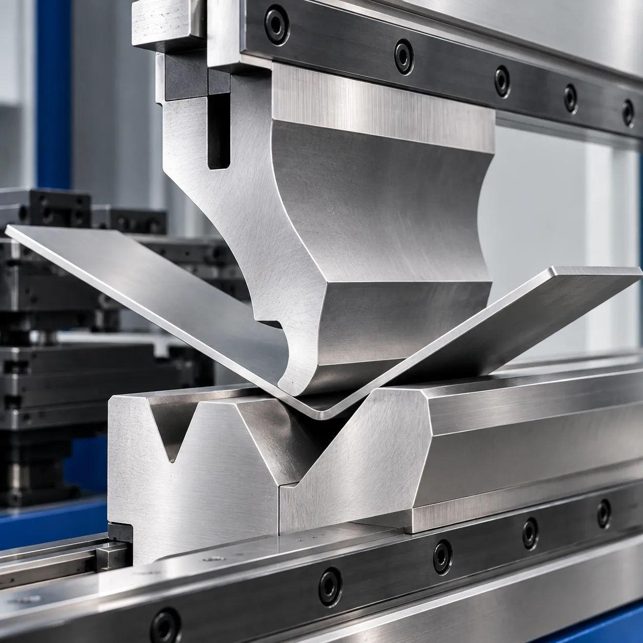
Formula details
Product Details
Overview
Rocker Press Brake Die: Product Overview
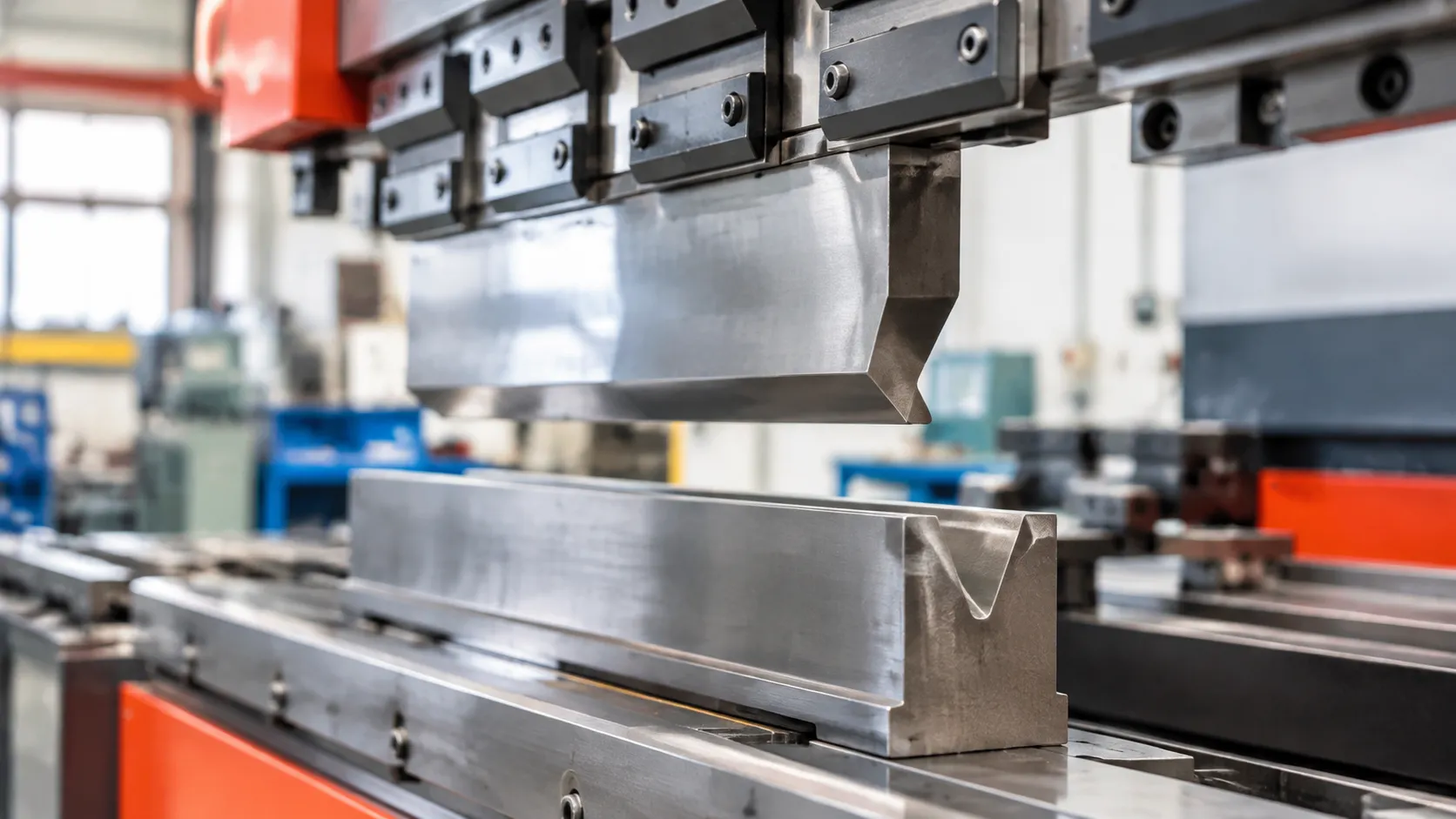
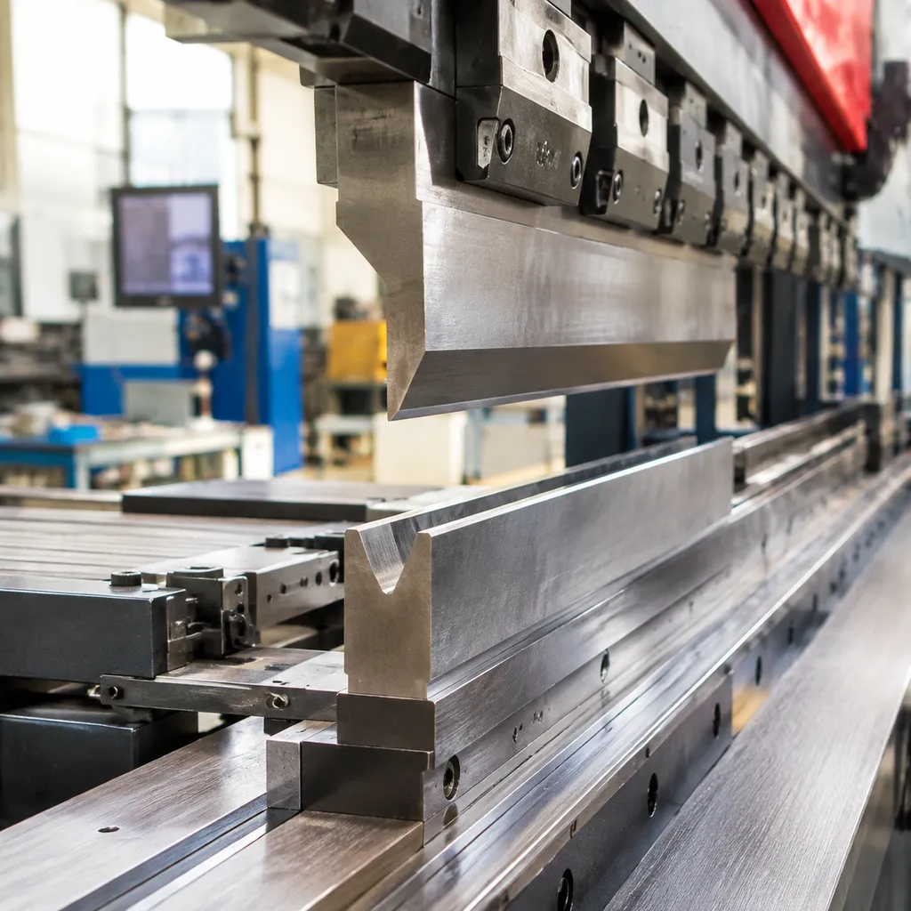
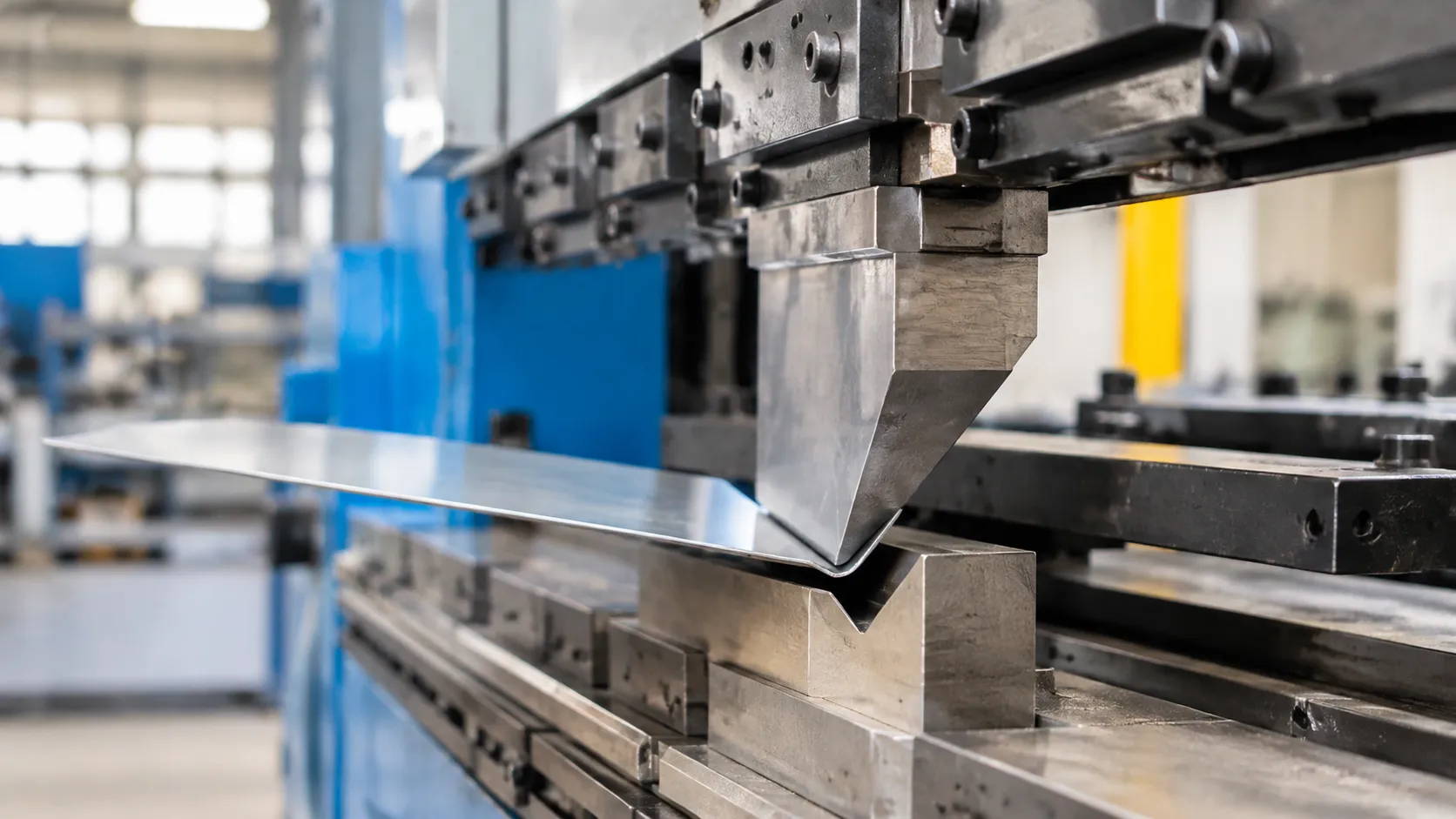
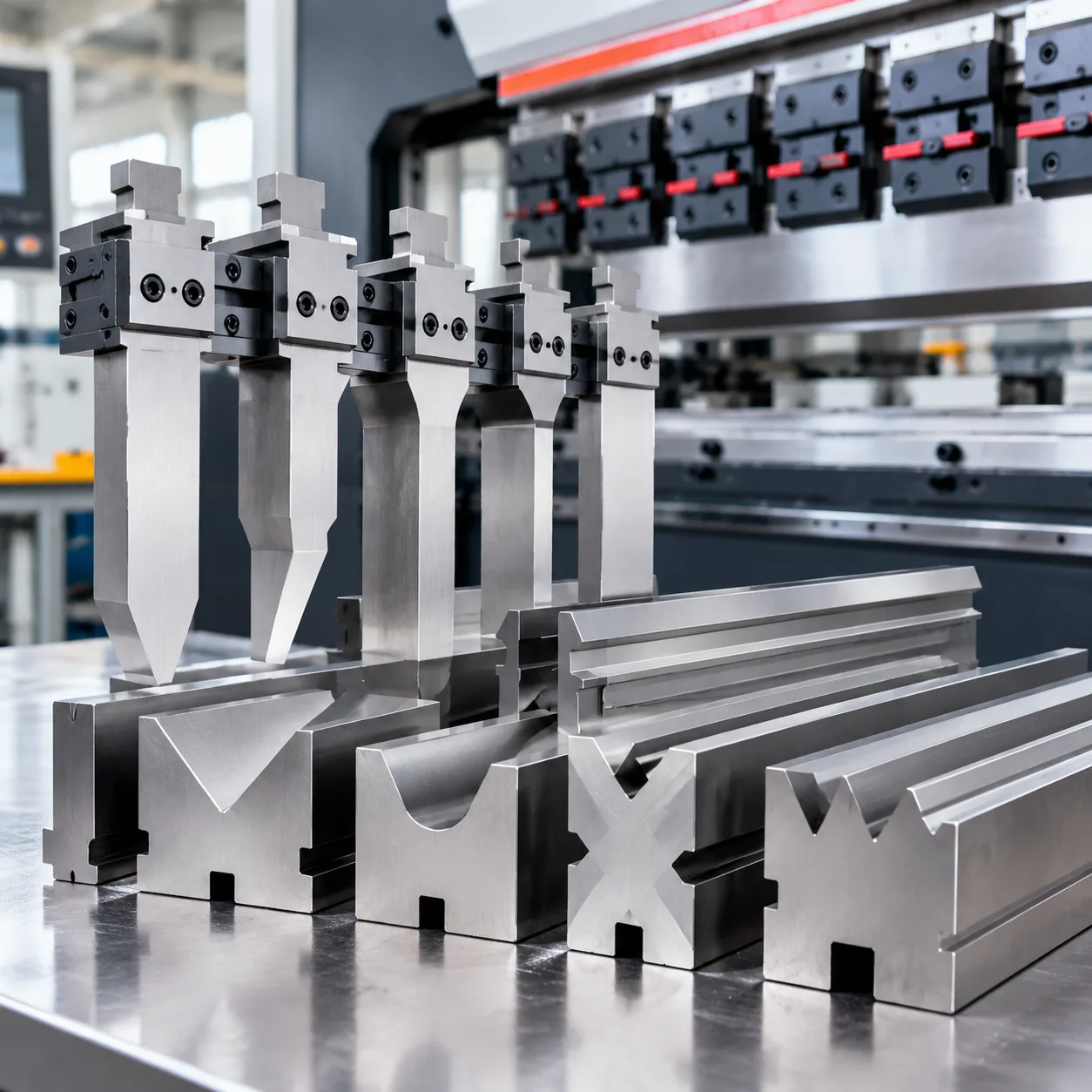
A rocker press brake die is a specialized lower bending tool engineered to replace standard sliding friction with smooth, rotating movement. By replacing the stationary shoulder radii of traditional dies with pivoting inserts, this tooling provides clean, mark-free bends on delicate, polished, and pre-coated sheet metals.
Core Tooling Components
We engineer our rocker bending dies with three primary structural elements to ensure repeatable precision under load:
- Die Saddle (Base Body): High-tensile tool steel block precision-machined with semicircular pockets and standard tangs to fit standard press brake clamping systems.
- Twin Rocker Inserts: Dual cylindrical, precision-ground tool steel rollers that sit in the saddle pockets to directly contact and support the workpiece.
- Return Spring and Pin Assembly: Mechanical elastomeric or spring-loaded pins that automatically return the rocker segments to their level starting position after every stroke.
How the Rotating Rocker Mechanism Works
In a standard bending setup, sheet metal drags violently over static die shoulders, creating high friction, surface marring, and edge drag.
A rotary press brake die changes this mechanical dynamic entirely:
- Initial Sheet Rest: The flat sheet rests flat across the level surfaces of both rocker inserts.
- Pivoting Descent: As the upper punch descends, the rocker inserts immediately pivot inward in their saddle seats.
- Rolling Wrap: The inserts roll alongside the metal rather than sliding against it, wrapping the material smoothly around the punch tip.
- Instant Reset: Once the punch clears the part on the upstroke, integrated return springs snap the rocker inserts back to dead level, ready for the next cycle.
This rolling action eliminates material draw-in friction, stabilizing the sheet throughout the stroke and preventing edge slippage.
Direct Comparison: Rocker Die vs. Conventional Fixed V-Die
| Performance Factor | Rocker Press Brake Die | Conventional Fixed V-Die |
|---|---|---|
| Material Contact | Rolling contact via pivoting rockers | Sliding friction over static die shoulders |
| Surface Finish | Mark-free; preserves pre-painted, polished, or soft metals | Common tool witness lines and severe galling |
| Minimum Flange Length | Bends ultra-short flanges without falling into the die | Requires broad flange to bridge the V-opening |
| Cutout Integrity | Prevents distortion on holes placed near the bend line | Often stretches and deforms adjacent cutouts |
| Forming Tonnage | Reduced tonnage demand due to zero shoulder drag | Higher tonnage required to overcome sliding friction |
| Sheet Movement | Controlled, gradual folding without aggressive sheet flip | Prone to violent back-gauge slap and operator hazard |
Key Benefits of Rocker Tooling
Mark-Free Bending on Polished and Pre-Painted Sheets
Traditional dies drag sheet metal across hardened V-shoulders under heavy load, galling soft alloys and scratching protective films.
Zero Die Scuffing: The rocker inserts pivot with the sheet throughout the stroke, creating a true mark-free bending die action.
Coating Protection: Mirror-finish stainless steel, prepainted coil, anodized aluminum, and soft copper exit the press without gouges, scuffs, or burnished streaks.
Elimination of Protective Tapes: We eliminate the need for disposable urethane tape or film backings, saving setup time on every batch.
Short Return Flanges Without Part Distortion
Conventional V-dies require a minimum flange length so the sheet bridges both die shoulders without falling into the V-cavity.
Tiny Flange Capability: Because the workpiece rests continuously on rotating rocker lobes, you can form significantly shorter, narrower flanges.
Close-to-Edge Holes: Holes, cutouts, and slots punched near the bend line stay round instead of stretching or warping under tension.
Consistent Flange Widths: Referencing the press brake die size chart and dimensions guide helps verify minimum leg heights and clear tooling profiles before production.
| Forming Challenge | Conventional Fixed V-Die | Rocker Press Brake Die |
|---|---|---|
| Sheet Contact | High-friction sliding over die shoulders | Rotating insert supports and rolls with sheet |
| Cosmetic Finish | Visible drag lines, die rub marks | 100% mark-free sheet surfaces |
| Minimum Flange | Typically requires 4× to 6× material thickness | Up to 50% shorter return flanges |
| Cutout Integrity | Holes near bend line stretch oval | Holes and slots remain geometrically true |
| Secondary Labor | Manual polishing, buffing, deburring | Straight to assembly or paint line |
Controlled Sheet Movement During Press Descent
Standard air bending causes sheet whip as the blank snaps into the V-groove. A rotary press brake die stabilizes the stock from initial contact to bottom dead center:
No Material Slip: The rocker inserts cup the blank immediately, preventing backgauge hop or front-to-back shift.
Reduced Sheet Snap-Back: Rotating support cradles the workpiece as it forms, dampening aggressive sheet recoil on wide panels.
Improved Operator Safety: Less erratic plate movement translates directly to safer part handling on large sheet runs.
Slashing Secondary Finishing Costs
Secondary grinding, hand-buffing, and part rework eat into operating margins fast.
By forming parts cleanly the first time, our rocker bending die setups remove offline buffing stages entirely.
Clean, distortion-free bend edges mean weld prep and corner fit-ups assemble faster without gap variations.
Scrap rates drop to near zero on expensive pre-anodized and brushed sheet goods.
Reliable Forming Across Diverse Alloys
A single rocker die handles diverse sheet tempers and alloys without requiring custom shoulder radius tweaks:
Mild & High-Strength Steels: Handles standard cold-rolled sheet as well as high-tensile structural grades cleanly.
Stainless Alloys: Delivers scratch-free results on 304 and 316 brushed finishes without work-hardening the bend corners prematurely.
Aluminum & Soft Metals: Eliminates material galling and aluminum pickup on the die surface during repetitive cycles. For standard setups and capacity checks, cross-reference our press brake V-die opening guide and selection tips to balance tooling load and material thickness.
Technical Specifications: Rocker Press Brake Die
| Specification Parameter | Standard Range / Metric Dimension | Imperial Standard |
|---|---|---|
| Material Thickness Capacity | 0.5 mm – 6.0 mm | 26 Gauge – 1/4 in |
| Standard Segment Lengths | 500 mm, 515 mm, 835 mm | 19.7 in, 20.2 in, 32.8 in |
| Sectional Segment Sets | Split sets (10 mm to 100 mm cuts) | 0.5 in to 4 in sectional cuts |
| Machining Tolerance | ±0.01 mm (working surfaces) | ±0.0004 in |
| Tang Compatibility | European Precision, Amada, American standard | Standard tang options |
Critical Tool Dimensions, Section Lengths, and Tolerances
Holding strict tolerances prevents angle variance when running long sheet production. Our CNC-ground die bodies and precision-fitted rocker saddles eliminate lateral deflection under full bending load.
- Working heights: Standardized tooling heights ensure easy staging alongside matching punches without shimming.
- Segmented sets: Precision section cuts allow quick staging for box forming, deep return channels, and custom enclosure profiles.
- Interchangeable lengths: Die sections align seamlessly end-to-end to deliver unbroken bend lines across full bed lengths.
Tool Steel Grades, Heat Treatment, and Surface Hardness
Rocker tooling experiences concentrated rolling stress along the rocker seats and working radii. We machine our die bodies and rocker inserts from premium alloy grades, detailed in our guide to press brake die steel, ensuring exceptional toughness and compressive strength.
- Base die body: 42CrMo / AISI 4140, quenched and tempered to 28–32 HRC for long-term core structural stability.
- Rocker inserts: High-carbon, high-chromium tool steel (Cr12MoV / AISI D2) vacuum-hardened to 58–60 HRC to resist wear and prevent deformation.
- Surface finish: Ground to Ra 0.4 µm to guarantee smooth insert rotation and eliminate friction against sensitive sheet metal.
Tooling Configurations: Solid vs. Segmented Dies and Interchangeable Inserts
Choosing the proper configuration depends on batch variety and part geometry. We manufacture two core setups designed for fast line adaptation:
- Solid long-length dies: Best for uninterrupted architectural panels, trim profiles, and full-length bending runs requiring consistent baseline support.
- Segmented modular blocks: Optimized for short-run job shops requiring quick length adjustments for multi-sided box folding.
- Interchangeable rocker inserts: The lower die body remains clamped in your machine while you swap out the replacement rocker die insert set to handle different sheet thicknesses or radius requirements, cutting tooling changeover time in half.
Target Industrial Applications for Rocker Press Brake Tooling
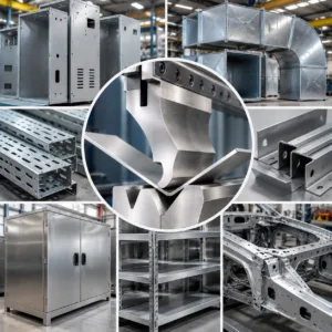
We deploy the rocker press brake die across operations where standard V-dies ruin surface finishes, pull short flanges into the die cavity, or warp features close to the bend line.
Architectural Panels, Facades, and Decorative Trim
Architectural fabrication demands zero visible die lines on premium materials like brushed stainless, anodized aluminum, and pre-painted composite panels.
Zero surface galling: The rotating inserts support the material throughout the stroke instead of dragging across hard shoulders, pairing effectively with non-marking press dies for scratch-free metal forming.
Flawless reveal edges: Long wall panels and exterior trims maintain uniform angular accuracy across full sheet lengths without die witness marks.
Electrical and Electronic Enclosures with Tight Cutouts
Server racks, control cabinets, and power distribution boxes often feature dense hole patterns and narrow perimeter flanges right next to the bend line.
Hole integrity: Standard dies stretch holes placed near the bend radius; a rotary bending die clamps the sheet face, preventing hole distortion.
Short return flanges: Operators can form narrow edges that would otherwise slip and drop into a traditional wide V-opening.
HVAC Ductwork, Covers, and General Fabrication
High-mix sheet metal fabrication environments handle frequent gauge changes and varying flange profiles for access panels, dampeners, and transitional ducting.
Consistent geometry: Prevents edge flare and corner blowout on galvanized and prepainted sheet stock.
Reduced tonnage wear: The smooth pivot action lowers the required forming load, extending tooling life on repetitive, high-volume runs.
Automotive and Transportation Bracket Forming
Structural clips, stiffening ribs, and mounting brackets in transit equipment require high repeatability without micro-fracturing along high-stress bend lines.
High-strength alloys: Handles advanced high-strength steels (AHSS) and structural aluminums with minimal springback variability.
Compact bracket shapes: Forms complex, multi-bend profiles without the part colliding with standard lower tool shoulders.
Custom Complex Bends with Strict Aesthetic Standards
For retail fixtures, appliances, and high-end metal displays, visual quality defines part acceptance.
Eliminates post-finishing: Parts move directly from the press brake to powder coating or assembly without grinding out tool scars.
Asymmetrical and narrow bends: Allows secure forming of offset flanges, tight stepped bends, and sensitive finished alloys without protective tape or films.
Material and Forming Considerations
Getting predictable bends with a rocker press brake die comes down to balancing raw material traits with precise machine inputs. Unlike fixed tooling, the dynamic action of a rotary bender changes how forces move through your sheet, demanding specific attention to thickness, yield strength, and setup limits.
Handling Sheet Thickness, Tensile Strength, and Springback
Every alloy reacts differently when the rocker inserts pivot. High-tensile stainless steel exerts severe pushback compared to soft aluminum, which directly impacts your final bend angle and tool life.
- Material thickness ($T$): Rocker tooling thrives within defined gauge ranges. Running stock over the rated pocket depth prevents the rockers from rolling smoothly, causing premature tool wear.
- Yield and tensile strength: Higher strength alloys resist the initial wrap. We compensate by overbending slightly to counter elastic recovery.
- Springback compensation: Because the rotary inserts maintain continuous contact, springback is more consistent than in standard air bending. Always factor in extra stroke depth to account for material memory:
- Soft Aluminum (5052-H32): Minimal springback (1° to 2°)
- Mild Steel (CR4 / A36): Moderate springback (2° to 3°)
- Stainless Steel (304 / 316): High springback (4° to 6°)
Bend Geometry Calculations: Radius, Flange Length, and Hole Clearance
Using a specialized rocker die for sheet metal allows you to push part geometries closer to physical limits than standard vee tooling allows. To keep parts within tolerance, use these baseline design rules:
| Geometry Parameter | Standard V-Die Limit | Rocker Press Brake Die Capability | Rule of Thumb |
|---|---|---|---|
| Minimum Flange Length | 6× to 8× Sheet Thickness | 2.5× to 3.5× Sheet Thickness | Must span across both rocker pivot centers |
| Hole-to-Bend Clearance | ge 3× Material Thickness | ge 1.5× Material Thickness | Rockers support the web, stopping hole stretch |
| Inside Bend Radius ($IR$) | Dependent on V-opening width | Governed by upper punch tip radius | Match with the proper punch radius profile |
Pairing your setup with the right upper tooling is critical. When planning your tool stack, fabricators often reference how to select the right press brake punch radius to ensure the inside corner sets cleanly without fracturing the sheet.
Press Brake Tonnage, Stroke Control, and Forming Parameters
A rocker die requires noticeably less forming force because the material is folded smoothly rather than dragged over sharp shoulder radii. Still, strict machine programming is required to protect the inserts.
- Tonnage requirements: Mechanical rotary action lowers friction, reducing required machine tonnage by roughly 20% to 30% compared to bottom bending in conventional metal forming press brake dies. Never exceed the maximum rated metric tonnage per meter marked on the die body.
- Stroke depth control: Rocker tools work via bottom-assisted folding. Setting the lower dead center (BDC) too deep will crush the rocker inserts into their saddles.
- Approach and bending speed: Set the approach speed to drop smoothly into mute point. Transition to a controlled bending speed (typically 8 to 12 mm/s) to let the rockers rotate in tandem with material displacement, eliminating kick-up and surface drag marks.
Press Brake Compatibility
Machine Tonnage, Bed Length, and Open Height
Before mounting specialized rotary press brake tooling, we evaluate three primary machine constraints:
- Available Tonnage: Rocker dies reduce frictional resistance, frequently demanding up to 20% to 30% less bending force than standard V-dies. However, your machine frame and hydraulic system must deliver adequate force across the entire profile length without localized bed deflection.
- Daylight and Open Height: The combined stack height—upper punch, workpiece thickness, and the rocker press brake die assembly—must leave ample stroke clearance for raw sheet feeding and formed flange removal.
- Usable Bed Length: We supply tool bodies in solid runs or segmented sections to match your exact bed dimensions, ensuring uniform clamping across the entire length of your lower beam.
Tool Holder Clamping Styles and Lower Tang Dimensions
To guarantee seamless integration across global shop floors, we engineer our lower die tangs to match your existing receiver setup. Whether retrofitting an existing machine or executing a standard press brake die replacement for American and European styles, tang precision dictates tool rigidity and centerline accuracy.
| Clamping System | Standard Tang Dimensions | Key Features |
|---|---|---|
| European / Promecam | 12.7 mm x 19 mm tang | Universal fit, precision ground base, safety groove standard |
| American Precision | 0.500 in (12.7 mm) tang width | Direct drop-in for standard American slotted beds |
| New Standard / Wila / Trumpf | CNC hydraulic or pneumatic clamping | Pin-locating systems for rapid auto-seating and high-tonnage stability |
| Custom / Planer Style | Tailored to machine slot | Engineered directly to non-standard bed slots and spacer plates |
Checklist to Confirm Tool Holder Fit
Follow this pre-purchase checklist to confirm that your press brake forming tool drops in without machine modifications:
- Measure the Bed Slot Width and Depth: Verify lower receiver slot dimensions with a caliper to ensure tang tolerance fits without side play.
- Calculate Closed Height: Subtract the rocker die height and punch height from your maximum stroke to ensure positive clearance at the bottom of the stroke.
- Check Tonnage Distribution Limits: Confirm your machine's tons-per-foot or tons-per-meter rating exceeds the calculated forming load of the target alloy.
- Confirm Clamping Bar Reach: Ensure your mechanical set-screws or hydraulic clamps engage the center of the die tang securely.
- Assess Backgauge Travel: Check that the lower die body does not obstruct the backgauge fingers during small-flange stops.
Installation and Setup Workflow for Rocker Press Brake Tooling
Setting up a rocker press brake die correctly prevents premature wear, eliminates tool binding, and guarantees mark-free parts right from the first stroke. I always treat rotary tooling with higher precision than static tooling because moving components demand clean contact surfaces and balanced clamping forces.
Pre-Installation Inspection of Rocker Seats and Contact Faces
Before lifting the tool into the machine, take five minutes to prep the components:
- Inspect the rocker seats: Check the saddle pocket for metal chips, scale, or dried lubricants. Even a tiny metal chip beneath a rocker insert causes uneven seating and angular variation across the bend.
- Examine the pivot surfaces: Ensure each insert rolls freely without drag or binding. Wipe down the bearing surfaces and apply a light coat of high-pressure machine oil or anti-seize paste.
- Check the tang and bed shoulders: Run a stone over the lower tang and bed contact flats to eliminate burrs or nicks picked up during handling or storage.
Proper Bed Seating, Clamping, and Punch-to-Die Alignment
Aligning a rotary press brake die requires consistent seating before tightening lower clamps:
- Seat the die flat: Lower the die holder onto the machine bed. Ensure the tang drops fully into the bed slot without bottoming out prematurely on debris.
- Snug, do not torque: Lightly snug the manual or hydraulic clamps so the die block can float slightly for centering.
- Center with the upper punch: Bring the punch down into the center groove of the rocker die under minimal tonnage. Verifying alignment using our press brake die clearance guide for better bending ensures the punch tip centers evenly without pinching one rocker harder than the other.
- Lock the clamps under load: Maintain light contact between the upper punch and the rocker inserts, then torque the bed clamps to their specified ratings. This locks the tooling precisely parallel to the ram stroke.
First-Part Test Bend Validation and Dimensional Sign-Off
Never run production on a rocker press brake die without validating setup parts across three checkpoints:
| Checkpoint | What to Look For | Corrective Action |
|---|---|---|
| Surface Finish | Check sheet exterior for witness lines, rub marks, or galling. | Wipe down rockers; confirm material is rolling rather than sliding. |
| Bend Angle Uniformity | Measure the formed angle at both ends and the middle of the sheet. | Adjust machine crowning or shim the die block if ends diverge. |
| Flange Length & Hole Position | Verify that short return flanges hold spec and nearby holes stayed round. | Adjust backgauge positions and ensure material sits square on rockers. |
Once the test part passes inspection, lock the CNC program parameters and begin the run.
Maintenance and Tool Care for Rocker Press Brake Dies
Debris Removal and Cleaning Abrasive Sheet Residue
Laser-cut scale, zinc flakes from galvanized sheets, and aluminum dust inevitably settle into the die saddle during heavy production runs. If left unchecked, this abrasive grit packs beneath the inserts, restricting smooth rotation and scoring the tool pocket.
- Daily Blow-Down: Clear out dry particulate between shifts using dry shop air across the entire saddle length.
- Solvent Flush: Wipe down the rotary cavity periodically with an industrial degreaser to dissolve bonded metal fines and old grease deposits.
- Surface Wipedown: Never use aggressive stone abrasives inside the insert seats; use scotch-brite pads or brass wire brushes to clean contact shoulders without changing tolerances.
Lubrication Intervals and Recommended Grease Types
A rocker bending die requires consistent film strength to handle heavy forming pressures without metal-to-metal galling.
- Grease Selection: We recommend extreme-pressure (EP) lithium-complex grease with molybdenum disulfide ($MoS_2$) or heavy-load synthetic grease. For cleanrooms or pre-painted sheet runs prone to contamination, use high-viscosity dry-film graphite spray.
- Frequency: Lightly grease the saddle contact points every 40 to 50 operating hours. For high-cycle automated cells, inspect and reapply lubricant weekly.
- Application Rule: Apply a thin, uniform coating inside the saddle curve before dropping in the rockers. Avoid over-packing grease, which can trap abrasive laser slag against rotating faces.
Wear Inspection: Galling, Micro-Cracks, and Rotational Clearance
Regular mechanical audits prevent minor surface wear from developing into broken tooling or scratched production sheets. When servicing your lower tooling, we also check our upper press brake punches to ensure the whole system maintains proper load alignment.
- Rotational Clearance: Rocker inserts should pivot freely across their entire stroke without lateral binding or excessive slop.
- Galling Checks: Inspect the contact radii and curved saddle pockets for pick-up, adhesive scoring, or dull flat spots.
- Crack Detection: Check insert ends and saddle stops under bright light for micro-fractures caused by repeated cycle fatigue or accidental tonnage spikes.
Safe Tool Storage and Ordering Replacement Rocker Inserts
Store rotary tooling carefully to protect precision-ground surfaces between production runs:
- Corrosion Control: Coat clean tooling with moisture-displacing rust-preventative oil before storing.
- Storage Environment: Keep tooling off concrete floors in horizontal wooden cradles or compartmentalized polyurethane racks to avoid nicking precision edges.
- Sourcing Spares: Keep a matched replacement rocker die insert set in stock for your high-wear stations. When ordering replacements, provide your tool segment length, insert radius size, and die saddle serial mark to ensure drop-in fitment without post-machining.
Troubleshooting Common Bending Defects with a Rocker Press Brake Die
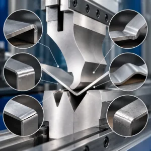
Even high-precision rotary bending tools can run into defects on the shop floor if setup variables drift. I look at troubleshooting practical issues systematically to keep parts clean and within tolerance.
Resolving Unexpected Die Witness Marks or Scoring
A rocker press brake die is designed to eliminate scoring by rolling with the sheet rather than sliding across it. If you suddenly see witness marks or scuffing on delicate materials like aluminum or polished stainless, check these root causes:
Metal fines trapped in the saddle: Laser scale or shearing burrs get trapped between the rotating insert and the die body, creating friction points. Clean the seats thoroughly with compressed air and degreaser.
Galling on contact surfaces: If the rocker insert surface picks up material, stone the contact face smooth or swap in a replacement rocker die insert before running pre-painted inventory.
Wrong clearance radius: If the sheet wraps too tightly around the insert edge, mechanical pressure spikes. Ensure your rocker radius matches your sheet thickness.
Correcting Uneven Bend Angles Along the Part Length
Angular variations from one end of the bed to the other typically stem from machine deflection or improper seating:
Tool clamping inconsistency: Re-seat the die segments. Ensure the lower tang rests uniformly across the bed before torquing down the clamps.
Machine bed crowning: Rotary dies require consistent penetration depth across the entire workpiece. Adjust your press brake crowning system to eliminate center open-angle drift.
Comparison with fixed tooling: If standard setups consistently deflect, review our press brake die angles guide for springback selection to verify stroke depth adjustments across different sheet hardness levels.
Fixing Jammed, Stiff, or Sluggish Rocker Inserts
A sluggish insert ruins the rolling action, turning a mark-free bending die into a friction point:
Contamination buildup: Pull the rocker sections, blow out metal dust, and clean the cradle channels.
Over-greasing with sticky lubricants: Heavy, tacky grease traps fine metal dust and turns into an abrasive paste. Use a light, high-pressure dry lubricant or light EP oil according to shop conditions.
Mechanical binding: Check the end stops and retainers. If an insert is pinched too tightly at the ends, back off the retaining plates slightly to allow free pivoting movement.
Adjusting for Inaccurate Flange Sizes and Springback Drift
When flange lengths wander or springback increases unexpectedly:
Material grain direction: Yield strength changes depending on whether bends run with or across the grain. Group your blanks to maintain identical grain orientation.
Bottom stop variation: Because a rotary press brake die contacts the material differently than standard V-tools, fine-tune backgauge positions to account for the pivot contact point rather than a theoretical V-opening center.
Tonnage and stroke calibration: Re-zero your Y-axis stroke to ensure consistent rotation and bend completion on every cycle.
Custom Tooling Engineering
We engineer custom rocker press brake die solutions tailored directly to your production drawings, machine envelope, and tonnage constraints through our dedicated custom tooling development workflow.
Required Part Specifications and File Formats
To evaluate your custom bending profile, we need clear part geometry and raw material data upfront:
- CAD Files: 2D drawings in DXF/DWG with marked bend lines and critical tolerances; 3D solid models in STEP/IGES formats for clearance validation.
- Material Properties: Exact sheet grade, alloy temper, raw thickness with tolerance range, and verified tensile/yield strengths.
- Bend Geometry: Required internal bend radii, minimum target flange lengths, and hole-to-bend edge distances.
- Press Brake Parameters: Machine make, total tonnage rating, bed length, stroke length, and lower tool holder tang dimensions.
Customizable Tool Parameters
Every component of our custom press brake tooling builds around your specific part challenges:
| Parameter | Standard Range | Custom Engineering Options |
|---|---|---|
| Rocker Insert Radii | R0.5 mm to R6.0 mm | Custom asymmetric radii, variable compound radiuses |
| Tool Length | 500 mm, 835 mm standard | Custom solid lengths up to 4000 mm, segmented split sets |
| Profile Geometry | 90° and 88° symmetrical dies | Acute 30°–60° pockets, asymmetric cutouts, deep-reach saddles |
| Mounting Tangs | Amada/European standard | Wila-Trumpf, American standard, Beyeler, or direct-mount bolting |
Engineering Review, Digital Simulation, and Milestones
We run a strict pre-production validation process to eliminate collision risks and guarantee bend accuracy before cutting steel.
- FEA and Forming Simulation: We model sheet contact kinematics and tonnage distribution to confirm that insert rotation clears complex returns and eliminates part marking.
- CAD Clearance Approval: You receive complete 3D tool assemblies showing the punch, rocker press brake die body, inserts, and sheet positioning for fitment sign-off.
- Precision Machining: Tool saddles, bases, and rotary inserts are CNC milled, deep hardened, and precision surface-ground to tight operating tolerances.
- Final Inspection & Tryout: We conduct dimensional verification, hardness testing, and physical stroke checks to verify smooth insert rotation under forming loads before shipment.
Quality Control and Inspection Standards for Rocker Press Brake Dies
Every rocker press brake die we build undergoes rigorous verification before it leaves our floor. Because rotary bending tools rely on tight clearances to guarantee mark-free sheet metal forming, our inspection process focuses on structural integrity, dimensional accuracy, and smooth mechanical action.
Incoming Raw Steel Inspection and Ultrasonic Testing
Reliable tooling starts with certified raw materials. We run thorough inspections on all tool steel billets before machining begins:
Material Certification: Verifying chemical composition against mill test reports.
Non-Destructive Ultrasonic Testing: Scanning raw blocks for internal voids, micro-cracks, or inclusions that could cause tool failure under high tonnage.
Grain Structure Check: Confirming uniform density to ensure even wear across the entire tool length.
Dimensional Accuracy, Profile Checking, and Hardness Testing
Our shop maintains tight tolerances across all critical surfaces to ensure drop-in alignment on your press brake. Under our documented tooling quality control procedures, every die undergoes multi-stage verification:
CMM and Optical Profile Inspection: Measuring saddle contours, tang dimensions, and insert radii to within microns.
Rockwell Hardness (HRC) Testing: Testing contact zones and pivot seats after heat treatment to verify specified surface hardness and core toughness.
Straightness and Parallelism Verification: Checking the working length on granite surface plates to prevent bend angle variation across long sheets.
Rocker Pivot Action Testing Under Load
A rocker die for sheet metal must pivot freely without catching or binding. Before final sign-off, we assemble the rotary inserts into their precision-ground saddles and mechanically cycle them:
Rotational Clearance: Checking for smooth, bind-free return action with proper grease clearance.
Load Seat Check: Confirming full surface contact between the insert body and the die cradle to distribute forming forces evenly.
Cycle Verification: Ensuring the rockers reset cleanly without sticking or lateral wobble.
Export-Grade Anti-Corrosion Protection and Crating
To guarantee that your rocker press brake tooling arrives ready for production, we pack each tool for long-haul ocean or air transit:
Cleaning and Degreasing: Removing all shop dirt, grinding dust, and metal fines.
Protective Coating: Applying industrial-grade rust-preventative oil to all ground surfaces, tangs, and inserts.
Barrier Wrapping: Sealing components in heavy vapor-corrosion-inhibitor (VCI) film.
Reinforced Wooden Crating: Securing tooling sections in custom-built, shock-resistant crates with custom wood blocking to prevent shifting during shipment.
Frequently Asked Questions
What is a rocker press brake die?
A rocker press brake die is a specialized lower forming tool featuring pivoting semicircular inserts inside a precision-machined saddle. Instead of dragging sheet metal over static tooling shoulders, the inserts rotate with the work piece as the punch descends. This rocking motion folds the material with minimal friction, delivering clean bends on sensitive materials.
How does a rocker die differ from a standard V-die?
Standard V-dies cause sliding friction because the sheet rubs across hard tool shoulders during the stroke. A rotary bending die replaces this sliding drag with a smooth pivoting action.
| Feature | Standard V-Die | Rocker Press Brake Die |
|---|---|---|
| Sheet Contact | Sliding friction across shoulders | Rolling support via rotating inserts |
| Surface Finish | Scratches, galling, witness marks | Clean, non-marking finish |
| Minimum Flange | Requires standard V-width coverage | Forms significantly shorter flanges |
| Hole Proximity | Cutouts distort near bend lines | Eliminates cutout and hole pull |
For conventional jobs with standard flange depths, shops often run a standard female press brake V-die for precise sheet metal bending. When cosmetic preservation is required, rocker tooling is the standard solution.
Can a rocker die eliminate surface marking entirely?
Yes. Because the contact points rotate with the sheet, you eliminate the dynamic friction that produces score lines, tool marks, and galling. Fabricators run polished stainless, mirror-finish aluminum, and pre-painted metals through these tools without protective film or secondary polishing steps. If your application involves continuous roller movement instead of pivoting rockers, specialized press brake dies with rollers for mark-free bending serve as another strong tooling option.
Can you bend short flanges with a rocker die?
A rocker die supports the sheet directly at the bend line from the start of the stroke. Traditional tooling requires the material to bridge across an open V-gap, causing narrow legs to fall inward and slip. With rocker inserts providing constant base support, you can form return flanges that are 30% to 50% shorter than standard tooling allows.
Which sheet metals and thicknesses are compatible?
We engineer rocker tooling for a wide range of sheet metals:
Aluminum alloys: 5052, 6061, and anodized or painted architectural skins.
Stainless steel: 304, 316, and brushed #4 finishes up to structural gauges.
Mild and carbon steels: Cold-rolled, hot-rolled pickled, and galvannealed stock.
Material gauges: Typically applied on light to medium gauges ranging from 0.5 mm to 6.0 mm, depending on insert radius and saddle sizing.
Will this die fit my existing press brake clamp system?
Yes. We machine the lower tangs to match your specific press brake configuration. Common mounting styles include:
European Precision Style: Standard 12.7 mm x 30 mm tangs with safety pins.
American Standard: Traditional 0.500-inch tang systems.
Bystronic / Beyeler Style: Specific bottom-mount track systems.
Direct Bed Mounting: Wide-base saddles bolted directly onto the lower bed.
How do you service and replace worn rocker inserts?
Servicing is straightforward and handles easily on the shop floor:
1. Loosen the end-stop retaining plates on the tool body.
2. Slide the replacement rocker die insert set out of the die saddle.
3. Clean the pocket of chips, mill scale, and old grease using solvent.
4. Apply a fresh coating of high-pressure synthetic grease inside the seat.
5. Slide in the new inserts, check for smooth rotation, and re-torque the end plates.
What technical information is required to get a quote?
To select or quote the correct rocker press brake tooling, supply the following parameters:
Material grade, tensile strength, and sheet thickness range.
Required inside bend radii and minimum return flange lengths.
Critical hole-to-bend line dimensions.
Press brake make, model, total tonnage, and lower tool holder style.
2D drawings (DXF/PDF) or 3D part models (STEP) of your most complex profiles.